We shall need centralizers to ensure the proper displacement of drilling fluids from the annular space and to place the cement evenly around the casing. Furthermore, it provides zonal isolation. In addition, They may help get the casing to the bottom, although this depends on the application.
While casing centralizers are not complex devices, proper selection and installation cannot be overemphasized. The overload of centralizer types available in the industry today can be overwhelming. At the same time, by understanding the advantages and disadvantages of each option, the drilling engineer can truly design fit-for-purpose casing centralization programs to overcome or mitigate specific wellbore challenges.
The article targets identifying the different casing centralizer types & understanding centralizer spacing while you are in the casing design phase. The focus will be on is on the following items:
- Casing Centralizers Different Types.
- Spacing formulas.
- The installation Patterns.
- Related Case Studies
Casing Centralizers Function
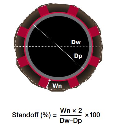
As mentioned above, we use the centralizers on different types of the casing string to provide clearance between the string and the wall of the hole. We call this clearance a standoff. The primary function is to centralize the casing in the hole and to prevent it from lying against the wall, thus providing a reasonable uniform cement layer around the casing.
Divergent Casing Centralizers Types
- Bow-spring Centralizers
- Rigid Centralizers
- Semi-rigid Centralizers.
- Mold-on Centralizers.
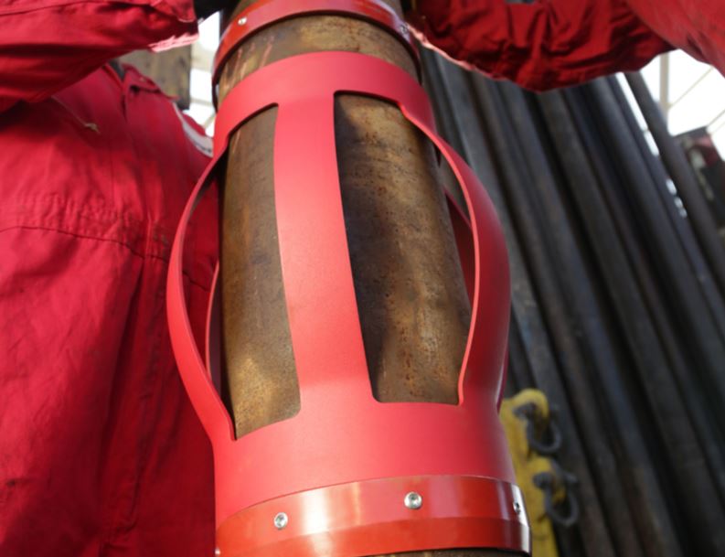
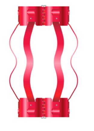
Bow Spring Casing Centralizer Type
Drilling Engineers use Bow Springs Centralizers to centralize casing in vertical or slightly deviated wells as its OD is more than the hole ID. Its bows are flexible to retract in narrow intervals of the upper casing and expand again in wide intervals of the wellbore.
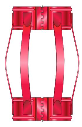
A vital term called the restoring force is the resistance force when there is a compression in the bow by 1/3 of its uncompressed height. This force also depends on the bow shape and stiffness. And it is essential as it is the primary factor in the effectiveness of the bow centralizers type.
Let’s assume we have heavy-weight casing and high inclination well; this situation may be beyond this centralizer’s capabilities.
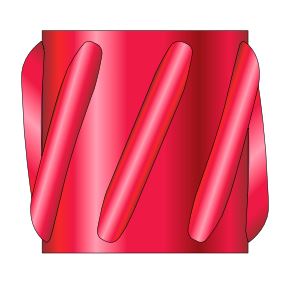
Rigid Centralizer

Solid, welded blade casing centralizer types offer high strength in horizontal and extended reach wells, providing a guaranteed standoff and function as bearings during the pipe rotation. These rigid bars are welded to the centralizer collars, giving the design strength and durability. Rigid centralizers come in various configurations, including hinged and slip-on, with straight blade and spiral designs.
Rigid centralizers are also available in composite materials, which can minimize drag, enabling conventional casing runs in long laterals regardless of the side force. Set screws are used in some configurations to lock the centralizer in place on the casing joint, providing extra holding force. However, since the centralizers are smaller than the wellbore, they will not offer as good centralization as the bow-spring type centralizers in vertical wells.
Semi-Rigid Centralizers
Semi-rigid casing centralizer types use double-crested bows to provide desirable features in both the bow-spring and rigid centralizer classes. The spring characteristic of the bows allows the semi-rigid centralizers to compress to get through tight spots and severe doglegs. The double-crested bow provides restoring forces that exceed the standards outlined in the API specifications and exhibits certain features usually associated with the rigid centralizers class.
Mold-On Type Casing Centralizers Type
The mold-on casing centralizer blade type, made of carbon fiber ceramic materials, can be applied directly to the casing surface. The blade length, angle, and spacing design can fit specific well applications, especially for the close tolerance annulus. The non-metallic composite can also reduce friction in extended-reach laterals, preventing casing buckling.
Casing Centralizers Spacing
Any casing centralizer spacing should be sufficiently close to keep the casing-to-wall clearance at some acceptable minimum distance. The casing couplings or various types of attachable stops control the vertical travel of the centralizer.
The following equations apply to all pipes in standard oilfield service.

- Where:
- F = force on each centralizer if spaced Cs feet apart (lbf)
- W= weight of casing (lb/ft)
- θ = average inclination angle (degrees) cs
- T = tension in the wall of the casing (lbf)
- TVD = true vertical depth
- S = distance from casing shoe to the centralizer in question
- ρmi and ρmo= the mud weights in and out of the casing, respectively
- DLS = dog leg severity
- Do outer casing diameter.
- di= inner casing diameter
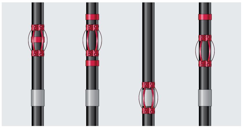
The selection of the proper Casing Centralizers installation pattern for mechanical cementing aids, i.e., centralizers, scratchers, turbolizers, etc., is essential to optimize casing running and cementing results.