The purpose Of accepting the process of the Mud Circulation System is to verify the hydraulic integrity of the high-pressure system at the rated working pressure.
Rig Acceptance | Lower KellyCock
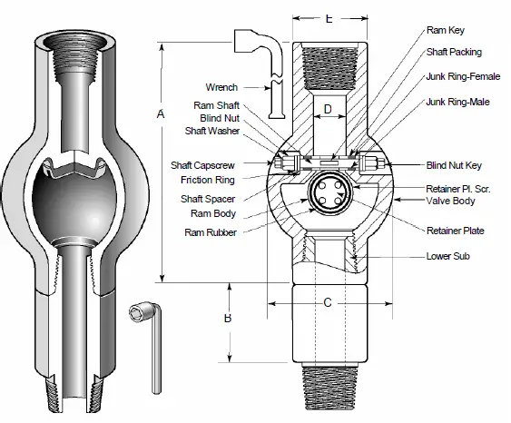
A Lower KellyCock or valve is a full-opening valve installed at the upper end of the Kelly saver sub or between the upper end of the drill pipe and the lower end of the rig Kelly. It also had an outside diameter equivalent to the OD of the D/P tool joint. Lower Kelly valves can be found for either square or hexagon Kellys.
This valve can be used to decrease mud loss or even stop drilling operations when the driller (Check also Driller Job Descriptions) removes the Kelly from the drill string. So to keep the mud inside the kelly, you will have to close the valve before removing the so that the hoses and mud in the Kelly stay there. The valve can quickly pay for itself with the cost of biopolymers, oil mud and other expensive drilling fluids. Some of the valves are not designed to cope with the external pressure that is encountered in the stripping operations.
Rig Acceptance | IBOP, including the spare one on the Rig floor
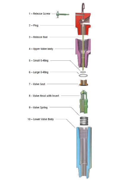
The Inside Blowout Preventer (I-BOP) Valve is a hard core check valve which is assembled with the drill string for use on the rig floor level as a shield from any well control issues as kicks at surface ( check also Kick warning Signs). It tend to be left in the drill string as long as required to regain well control with over-balanced pressure.
I-BOP valves can be provided with either API or any requested connections. IBOP valves are manufactured according to API 7-1 or NS1 latest edition. Also IBOP valves can be provided in both standard or H2S resistant versions and supplied according to Class 1 construction.
Mud System In Rig Acceptance | Top drive wash pipe
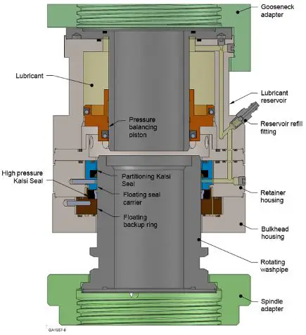
Drilling mud are flowed to drilling swivels and top drive drilling systems via wash pipe with a seal known as a “washpipe packing” assembly which is considered as a high-pressure swivel apparatus . This wash pipe packing assembly consists of a tubular component that is held stationary and through which the drilling mud flows under high pressure.
A rotating seal assembly of contact lip seals is mechanically connected to and rotates with the main shaft of the top drive system or swivel, and forms a dynamic isolation against the outer surface of the tubular wash pipe as the main shaft rotates while drilling operations. According to the high pressures and surface speeds involved in this arrangement, service life of the top drive washpipe packing is considered to be limited. Drilling mud leaks are therefore common on many drilling onshore/offshore rigs, resulting in contamination and damage to the related components and environmental disruption.
Mud System Acceptance | Rotary Hoses

Rotary Hoses are large-diameter (three to five in. inside diameter), high pressure flexible line used to fix the standpipe to the drilling swivel. Because of the flexibility nature of rotary hoses, it allows the kelly (and, the attached drill string and bit) to be moved up and down freely while drilling mud is pumped through the drill string. The simultaneous lowering of the drill string while pumping fluid is critical to the drilling operation.
Rig Mud System Acceptance | Drilling Stand Pipes
A rigid metal conduit that allows the passage of the high-pressure drilling fluid to move approximately one-third of the way up the Rig derrick, where it connects to a flexible high-pressure rotary hose. Many large drilling rigs are fitted with dual standpipe configuration so that they are able to reduce downtime to a minimum as if one standpipe requires repair.
Rig Acceptance | Rig Floor Mud Stand Pipe Manifold
The mud standpipe manifold is installed after the drilling fluids pumps with the purpose of directing the flow of drilling mud toward the drill line or drill string. An adjustable choke can be installed to bleed off pressure on the drill pipe, to reduce shock when breaking circulation in wells where loss of circulation is a problem, and to bleed off pressure between blowout preventers during stripping operations.
Rig Acceptance | Mud pumps manifold & discharge lines.
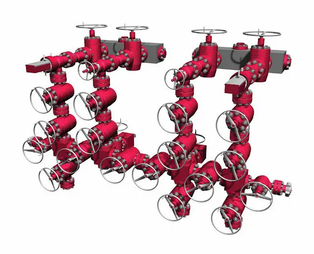
The game plan of lines and valves used to direct and control drilling mud on a mud pump area. The mud pump manifold on suction area is generally known as the inlet or low-pressure manifold. The related mud manifold located on the pump outlet is commonly known as the high-pressure or discharge manifold. In most cases, reference to the pump manifold relates to the high-pressure manifold.
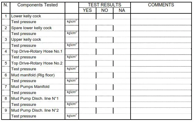
Testing Procedure For Accepting Process Of Mud Circulation System
- Connect the testing sub with the Top Drive saver sub; connect device with the testing pump or with the Cementing Unit. Ensure recorder is connected.
- Close the lower Kellycock. With water pressure up to the rated working pressure; keep the pressure for 10 minutes and record the results on the attached table.
- Repeat the test for the upper Kellycock.
- Continue testing all the components of the discharge lines down to the mud pumps to the maximum working pressure of each component. Record data in next table:
Other Items To Be Considered While Accepting Mud System On Any Drilling Rig
H.P. Mud Pumps
1 Number, make and type as per contract. :
2 State of maintenance satisfactory. :
Pump No.1. :
1 State of maintenance satisfactory. :
2 Suction equipped with filter. :
3 Suction equipped with Dampener. :
4 Discharging equipped with filter. :
5 Discharging equipped with Dampener. :
6 Dampener precharged at the pressure of psi
8 Relief valve properly installed :
9 Valve set at relief pressure of psi
10 Liner size installed on mud pump in
11 Surcharging pumps per contract
Pump No.2. :
1 State of maintenance satisfactory. :
2 Suction equipped with filter. :
3 Suction equipped with Dampener. :
4 Discharging equipped with filter. :
5 Discharging equipped with Dampener. :
6 Dampener precharged at the pressure of psi
8 Relief valve properly installed :
9 Valve set at relief pressure of psi
10 Liner size installed on mud pump in
11 Surcharging pumps per contract
Pump No.3. :
1 State of maintenance satisfactory. :
2 Suction equipped with filter. :
3 Suction equipped with Dampener. :
4 Discharging equipped with filter. :
5 Discharging equipped with Dampener. :
6 Dampener precharged at the pressure of psi
8 Relief valve properly installed :
9 Valve set at a relief pressure of psi
10 Liner size installed on mud pump in
11 Surcharging pumps per contract
Pumps discharging manifold:
1 Equipped with adequate valves:
2 State of maintenance satisfactory:
Pump discharging (rigid section) lines:
1 Dimension and type as per contract:
2 Proper safety clamps :
Rig floor Mud Manifold :
1 State of maintenance satisfactory :
2 Same type of valves :
3 Transmitters and gauges with isolation valves :
4 Provision for Mud Logging Unit pressure transmitter independent with isolation valve. :
5 Kill line as per contract and adequate :
6 Discharge line with needle type valve :
Stand Pipes :
1 Quantity and type as per contract. :
Vibrator Hoses on Standpipe :
1 With grade & API stamp. :
2 Make and type as per contract. :
3 Complete with safety clamps and chains. :
4 Hours total amount or installation date. N°
Rotary hoses :
1 With grade & API stamp. :
2 Make and type as per contract. :
3 Complete with safety clamps and chains. :
4 Hours total amount or installation date. N°
Mud tank
1 Quantity and capacity as per contract :
2 State of maintenance satisfactory :
3 Adequate drainage system :
Electrical agitators :
1 Quantity and type as per contract. :
Bottom guns: :
1 Quantity and type as per contract. :
Mud lab on mud tanks
1 State of maintenance satisfactory :
2 Self-closing door between Mud tank room and mud pump room.
3 Stairs, walk-way and grating as per rules and satisfactory
4 Mud tank with air-breathing equipment
5 Mud tank all safety alarms
Mud Mixing Equipment
1 Centrifugal pump as per contract :
2 State of maintenance satisfactory :
3 System layout satisfactory :
4 System allows the simultaneous operations of conditioning the mud circulating and making new mud:
Silos for cement
1 Number and capacity as per contract. :
2 Check the straightness of the lines. :
3 With weight indicator. :
4 With safety valves. :
Silos for barite and bentonite
1 Number and capacity as per contract. :
2 With weight indicator. :
3 With safety valves. :
4 Check the straightness of the lines. :
Surge tank for barite
1 Number and capacity as per contract. :
2 properly installed. :
Air-compressed bulk transfer system
1 As per contract. :
2 With air dryers. :
Shale shakers :
1 Number and type as per contract :
2 layout satisfactory :
3 State of maintenance satisfactory :
4 Cuttings discharge conveyor as per contract :
Sand trap:
1 State of maintenance satisfactory :
Mud Cleaner :
1 Type and equipment as per contract :
2 Feeding pump as per contract :
3 With proper gauge on discharge line :
4 State of maintenance satisfactory :
5 Cuttings discharge conveyor as per contract :
Degasser :
1 Type and equipment as per contract :
2 Proper vacuum gauge installed :
3 Feeding pump as per contract :
4 With proper discharge gauge :
5 State of maintenance satisfactory :
6 Gas discharge line safe and satisfactory :
Trip tank :
1 Trip Tank Type and equipment as per contract :
2 layout satisfactory :
3 State of maintenance satisfactory :
4 Level indicator visible from DRILLER :
Drilling Cuttings Collection System :
1 From shale shaker as per contract. :
2 Cuttings conveyor type as per contract. :
3 From mud cleaners as per contract. :
4 From Centrifuges as per contract. :
Mud Gas Separator :
1 Type and equipment as per contract :
2 Layout satisfactory :
3 State of maintenance satisfactory :
4 Line from choke manifold as per contractual drawing. :
Mud pit level indicator system :
1 Type and equipment as per contract.
2 Pit level sensor installed into mud tanks. N°
3 With alarm as per contract.