This article is one of 5 important articles about Mud logging unit equipment. These articles explain in detail the equipment used in standard mud logging units.
Measured Depth Determination
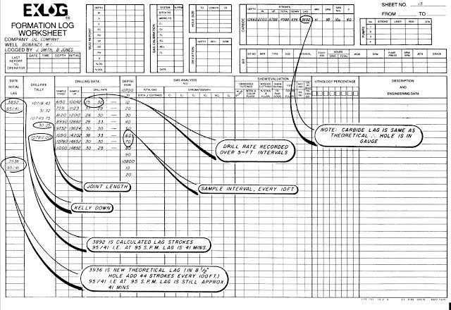
Depth is determined at the “Kelly down” position. This depth is the sum of the lengths of the kelly and the Drill String that are in the borehole below the Kelly bushing (or rotary table when a top dive system is used). To obtain this depth, all Drill Pipe, Drill Collar, Bottom Hole Assembly BHA, Stabilizers, Reamers & subs, etc. are measured with a metal tape measure.
The pipe to be measured is transferred from the pipe racks and placed on the “V door” ramp. The roughnecks then strap (measure) the pipe from the top of the box to the base of the pin. Lengths are normally measured to the hundredth of a foot (xx.xx). This information is noted in the “Pipe Tally Book”, which will usually look like this:
| 30.78 | S | 9256.32 |
| 31.26 | D | 9287.58 |
| 31.02 | -103- | 9318.60 |
The first column is the length of the drill pipe joint measured on the V door ramp. The second column is the joint’s position in the drill string (S = single, D = double, -103- = number of stands in the drill string). The third column is the total length of the drill string when that single is drilled down.
Since the total length is just the length of the Drill String in the borehole, to find the true “measured” depth at Kelly down, Kelly’s length (including any saver sub) must be added. So the total depth at Kelly down for 103 stands with a 42.50 feet Kelly is:
9318.60 + 42.50 = 9361.10
It is usual practice to add the Kelly at the start of drilling. When this happens, the logger’s depth will always be the kelly length deeper than the driller’s Pipe Tally Book (Check also Driller Job Descriptions).
When a top drive in a drilling rig system is used (stands are drilled, not joints), the Pipe Tally Book will look very similar:
| 93.77 | 102 | 9225.54 |
| 93.06 | 103 | 9318.60 |
Drill Rate Recorders
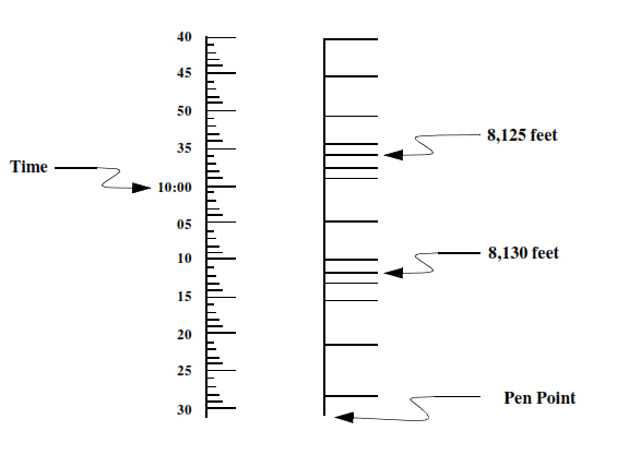
A Drill Rate Recorder (a mechanical device on the rig floor) measures depth and drill rate. The recorder is basically a rotating drum with a columnar chart attached to the drum. One column of the chart is a twelve-hour clock divided into minutes. Another column is under a pen, drawing a horizontal spike each time a foot is drilled.
By counting the number of minutes it took to drill the “logging interval,” feet/hour and meters/hour can be determined. Below the drum is a digital meter that will increase each time a horizontal spike is produced. This meter reading should be depth. As a cross-check, the driller will usually mark the depth on the chart each time a connection is made.
Figure 1 is an example of how to use the drill rate recorder to determine the drilling rate.
The main disadvantage of using drill rate recorders for depth and drill rate information is that they can be manipulated by the rig crew. The digital meter can be manually increased or decreased, especially when the meter and pipe tally do not agree. The recorder can also be turned off and on whenever it is “deemed necessary”.
Mud Logging Unit Systems For Determination Of Measured Depth & Drill Rate
To determine depth and drilling rate, many logging companies use systems independent of the drilling recorder, which monitors the height of the kelly or the position of the traveling block concerning the rotary table (RT) or rotary kelly bushing (RKB).
One such system uses a sensor that responds to changes in the hydrostatic pressure of a column of fluid (usually water) between a sensing device and a metal chamber (Kelly bottle) located near the gooseneck.
In “standard” mud logging unit equipment, a Bristol recorder (a circular, 8-hour chart) is used. The hydrostatic head acts against a diaphragm, and the pressure changes are mechanically transferred by connecting levers to a pen that records the changes on the circular chart. In more advanced mud logging unit equipment, the hydrostatic pressure variations are detected by a differential pressure transducer, and the electric signal is sent to the logging unit and recorded on a continuous, linear chart (Figure 2).
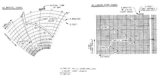
The charts are calibrated regarding depth units on one axis and time on the other. The amount of change in Kelly’s position and the time for that change are converted into drill rate. When the trace on the chart reaches a minimum (before the Kelly is raised for a connection), it is termed the “Kelly down” position.
By knowing what each successive “Kelly down depth” should be (from the pipe tally as new singles are added), it is possible to extrapolate the Kelly’s position throughout the drilling of the single and, therefore, have an accurate depth at all times.
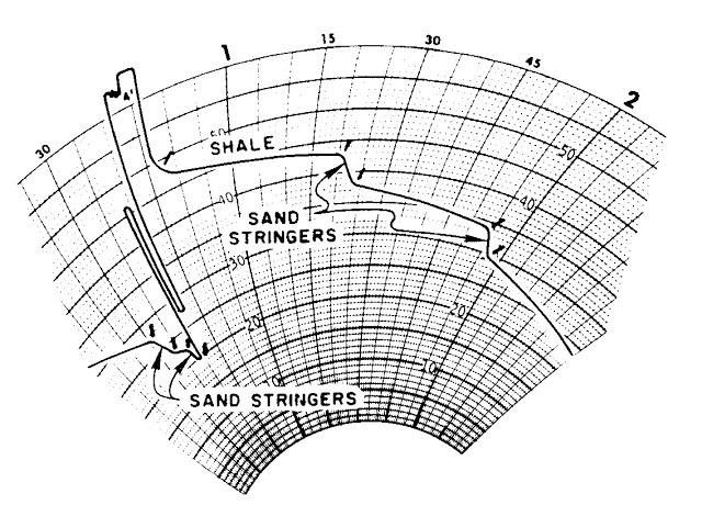
During drilling, as the depth increases, cuttings samples are prepared for correlation (Figure 3), using the mud pump stroke counters. When the end of a mud logging interval (sample interval) is reached, the readings on the pump stroke counters are totaled and entered onto the Data Worksheet in the Sample Finish column opposite the depth and time. The lag strokes (the strokes needed to displace the annular volume) are then added to this and entered in the Sample Up column. When the pump strokes have advanced to this Sample Up value, the sample for that particular interval will be at the surface, ready to be collected.
During sharp increases in the drilling rate (drilling breaks) and sharp decreases in the drilling rate (reverse drilling breaks), extra cutting samples should be collected and analyzed for lithology changes. However, since lithology changes may occur without a change in drilling rate, it cannot be relied upon entirely. After the drill cuttings have been examined, the rock type can be noted directly on the chart.
General rig operations can also be interpreted from the Kelly height chart (connections, circulating, etc.). Operations other than routine drilling should be noted directly on the chart for later reference. Also, any other items that may be helpful can be noted.
Correlation of the Drill Rate with Other Logs On Mud Logging Unit Equipment
The drilling rate is plotted in Track 1 of the formation evaluation logging. This plot should show the rate increasing from right to left, and is done for several reasons:
- The plot should match up with an SP or Gamma Ray log.
- It can be used for correlation with other logs to determine formation tops.
- It can be used for the interpretation of lithology.
To ensure correct correlation is occurring, the mud logging geologist must make notes (Figure 4) or consider the factors that may affect the penetration rate. The more common ones include:
Mechanical Factors
- Weight-on-Bit
- Rotational Speed
- Drill Bits Types
- Bit Wear (check also Bit Dullness)
Drilling Fluid Related
- Mud Density ( see also how to measure mud density on rig)
- Solids Content ( see also how to measure solid content on the rig)
- Fluid Loss ( see also how to measure the fluid loss on the rig)
Formation Characteristics
- Compressive Strength
- Hardness and Abrasiveness
- Porosity and Permeability
- Pore Pressure
Hydraulic Factors