When manufactured, the new drill pipe will be subjected by the manufacturer to a series of mechanical, tensile, and hydrostatic pressure tests & inspections by API Specifications 5A and 5AX. This will ensure that the pipe can withstand specified loads. A joint of drill pipe will however be used in several wells. When it has been used it will undergo some degree of wear and will not be able to withstand the same loads as when it is new.
It is extremely difficult to predict the service life of a drill string since no two boreholes experience the same drilling conditions. However, as a rough guide, the length of the hole drilled by a piece of drill pipe, when part of a drill string will be :
- soft drilling areas: 220000 – 250000 ft
- hard or deviated drilling areas: 180000 – 210000 ft
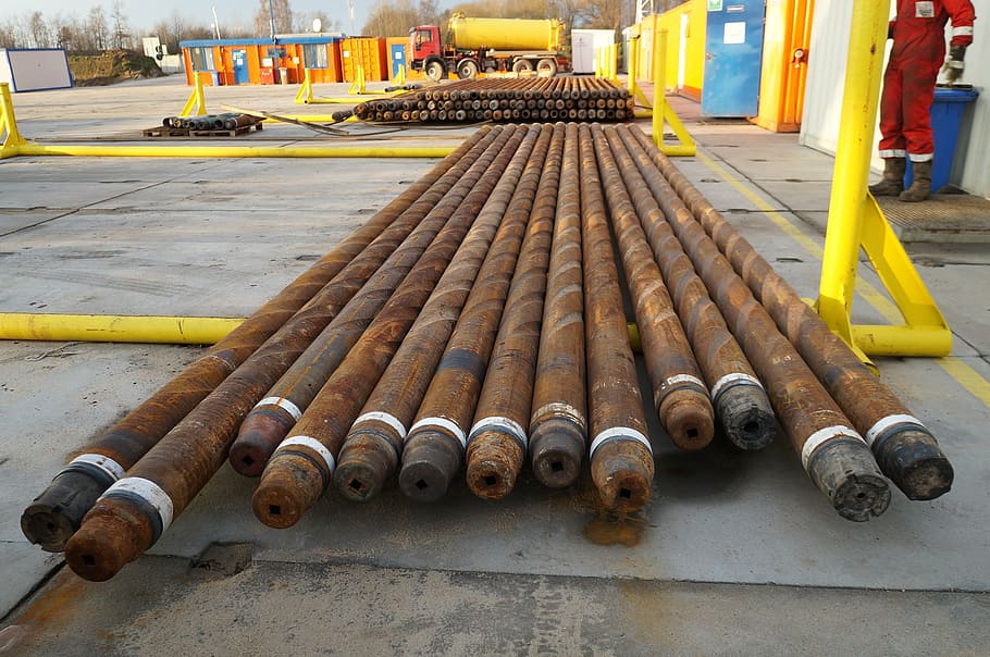
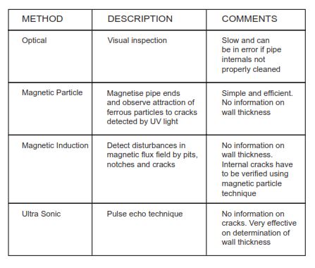
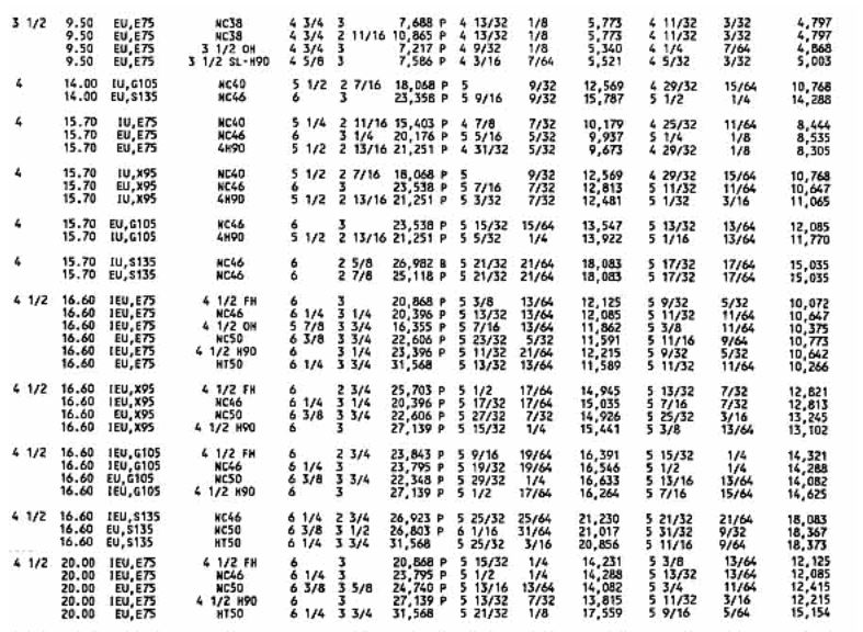
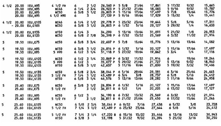
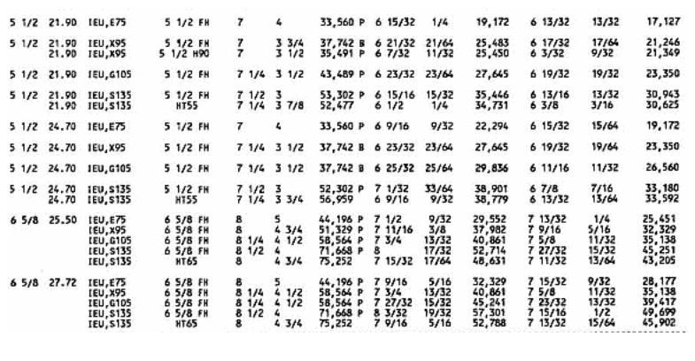
This means that a piece of drill pipe may be used on up to 25 wells that are 10,000 ft deep During the working life of the drill pipe it will therefore be necessary to determine the degree of damage or wear that the pipe has already been subjected to and therefore its capacity to withstand the loads to which it will be exposed in the future. Various non-destructive tests are periodically applied to the used drill pipe, to assess the wear and therefore strength of the pipe, and to inspect for any defects, e.g. cracks. The strength of the pipe is gauged based on the remaining wall thickness, or if worn eccentrically, the average minimum wall thickness of the pipe. The methods used to inspect drill pipes are summarised in Table 4. Following the inspection, the drill pipe is classified in terms of the degree of wear or damage which is measured on the pipe. The criteria used for classifying the drill pipe based on the degree of wear or damage are shown in Table 6. The ‘Grade 1 or Premium’ drill pipe classification applies to the new pipe or used pipe with at least 80% of the original wall thickness remaining. A classification of Grade 2 and above indicates that the pipe has sustained significant wear or damage and that its strength has been significantly reduced. The strength of some typical drill pipe sizes when new, and when worn, is shown in tables 11 and 12.
Drill pipes will generally be inspected and classified before a new drilling contract is started. The operating oil and gas company would require that the drilling contractor provide proof of inspection and classification of the drill string as part of the drilling contract. In general, only new or premium drill pipes would be acceptable for drilling in the North Sea.
Brief Of Drill Pipe Inspections to be performed:
Tool joint,
Visual: Visual examination of connections, shoulders, and tool joints and profile checks of threads, measurement of box swell
Dimensional 1: Measurement or Go-No-Go gauging of box OD, pin ID, shoulder width, tong space, and box counterbore.
Drill Pipe Tube,
Visual: Full-length visual examination of the inside and outside surfaces of used tubes
OD Gauge: Full-length mechanical gauging of the outside diameter of used drill pipe tubes
UT Wall Thickness: Measurement of the wall thickness around one circumference of the drill pipe tube using an ultrasonic thickness gauge
Electro Magnetic: Full-length scanning (excluding upsets) of drill pipe tube using the longitudinal field buggy type unit
Possible Thread Damages
- Broken threads
- Handling Damage
- Seal and sealing shoulder damage Thick threads
- Cuts and gouges
- Narrow threads (Shaved threads)
- Thread galling
- Wicker (Whisker)
- Not full crested threads
- Cracks
- Pitting
- Arc Bums
- Dents
- Threads not extending to the center of the coupling (threads within the J-area may not be perfect)
- Thread running out on the face
- Razor edge
- Feather edge
- False starting thread engaging actual starting thread
- Wavy threads
- Ovality
- Fins
- Burrs
- Galls
- Mashes
- Tool marks
- Seams
- Laps
- Grinds
- Dings
- Chatter
- Improper thread form
- Tom threads (Tears)
Drill Pipe Inspection Standards.
Through efforts of joint committees of API and IADC, inspection standards for the classification of used drill pipes have been established. The procedure outlined in Table 1 was adopted as a tentative API specification at the 1964 Standardization Conference and was revised and approved as a standard at the 1968 Standardization Conference.
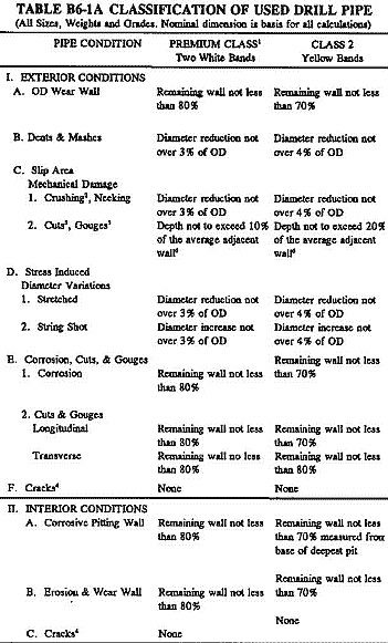
Notes on Table 1:
- The premium classification is recommended for service where it is anticipated that torsional or tensile limits for Class 2 drill pipe and tubing work strings will be exceeded. These limits for Premium Class and Class 2 API drill pipes are specified in Tables B2-2 and B2-3 respectively. Premium Class shall be identified with two white bands, plus one center punch mark on the 35° sloping shoulder of the tool joint pin (or the 18 sloping shoulders of the pm, if the 18 angles are furnished.)
- Drill Pipe inspection of this condition should be made to detect the presence of longitudinal and transverse cracks inside and outside.
- The remaining wall shall not be less than the value in I.E.2, defects may be ground out providing the remaining wall is not reduced below the value shown in I.E.1 of this table, and such grinding to be approximately faired into the outer contour of the pipe.
- In any classification where cracks or drill pipe washouts appear, the pipe will be identified with the red band and considered unfit for further drilling service.
- An API RP 7G inspection cannot be made with drill pipe rubbers on the pipe.
- The average adjacent wall is determined by measuring the wall thickness on each side of the cut or gouge adjacent to the deepest penetration. Additional revisions were made at the 1970 Standardization Conference to add Premium Class. At the 1971 Conference, it was determined that the drill pipe classification procedure be removed from an appendix to API Spec 7 and placed in API RP 7G as a recommended practice. At the 1979 API Standardization Conference, these guidelines were revised to also cover the classification of used tubing work strings. See Table 2.
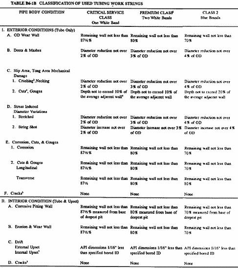
Table 2: Classification of Used Tubing Work Strings
Notes on Table 2:
- The guidelines established in this Recommended Practice have been in use for several years. The use of the practice and classification guide has been successful when applied in general application. There may be situations where additional inspections are required and/or a more specific engineering design is required to accommodate higher stress or a more corrosive environment.
Limitations of Inspection Capability.
Most failures of drill pipes result from some form of metal fatigue. A failure originates as a result of repeated or fluctuating stresses having maximum values less than the tensile strength of the material. Fatigue fractures are progressive, beginning as minute cracks that grow under the action of the fluctuating stress. The rate of propagation is related to the applied cyclic load and under certain conditions may be extremely rapid.
The failure does not normally exhibit extensive plastic deformation and is therefore difficult to detect until such time as considerable damage has occurred. There are no accepted means of inspecting to determine the amount of accumulated fatigue damage or the remaining life of the pipe at a given stress level.
Presently accepted means of drill pipe inspection are limited to the location of cracks, pits, and other surface marks; measurement of remaining wall thickness; measurement of outside diameter; and calculation of remaining cross-sectional area. Recent industry statistics confirm that a major percentage of tube body in-service failures occur near the upset runout or within the slip area. Special attention to these critical failure areas may be required during inspection to facilitate crack detection in some drill strings. Drill pipe which has just been inspected and found free of cracks may develop cracks after very short additional service through the addition of damage to previously accumulated fatigue damage.
Definition of a Crack.
A crack is a single line rupture of the pipe surface. The rupture shall (1) be of sufficient length to be shown by magnetic iron particles used in magnetic particle inspection or (2) be identifiable by visual inspection of the outside of the tube and/or by optical/ultrasonic shear-wave inspection of the inside of the tube.
Measurement of Drill Pipe Wall While Inspection.
Tube body conditions will be classified based on the lowest wall thickness measurement obtained and the remaining wall requirements contained in Table 1 for drill pipe and Table 2 for tubing.
The only acceptable wall thickness measurements are those made with pipe-wall micrometers, ultrasonic instruments, or gamma-ray devices that the operator can demonstrate to be within 2 percent accuracy by use of test blocks sized to approximate pipe wall thickness.
When using a highly sensitive ultrasonic instrument, care must be taken to ensure that detection of inclusion or lamination is not interpreted as a wall thickness measurement.
Determination of Cross Section Area (Optional).
Determine cross-sectional area by use of a direct indicating instrument that the operator can demonstrate to be within 2 percent accuracy by use of a pipe section approximately the same as the pipe being inspected. In the absence of such an instrument, integrate wall thickness measurements taken at 1-inch intervals around the tube.
Procedure
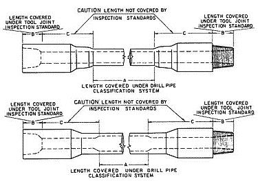
Used drill pipe should be classified according to the procedure of Table 1 and as illustrated in Figure 1 dimension A.
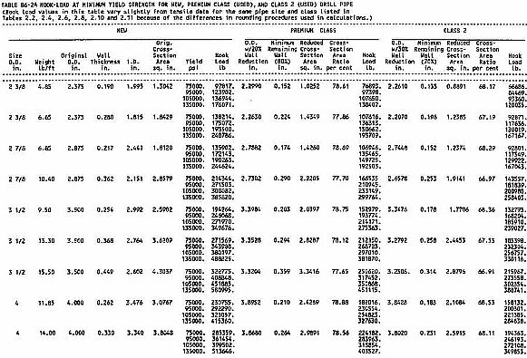
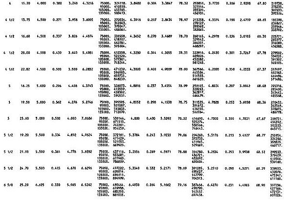
Maximum allowable hook loads for New, Premium, and Class 2 drill pipes are listed in Table 3
Values recommended for minimum OD and make-up torque of weld-on tool joints used with the New, Premium, and Class 2 drill pipe are listed in Table 4.
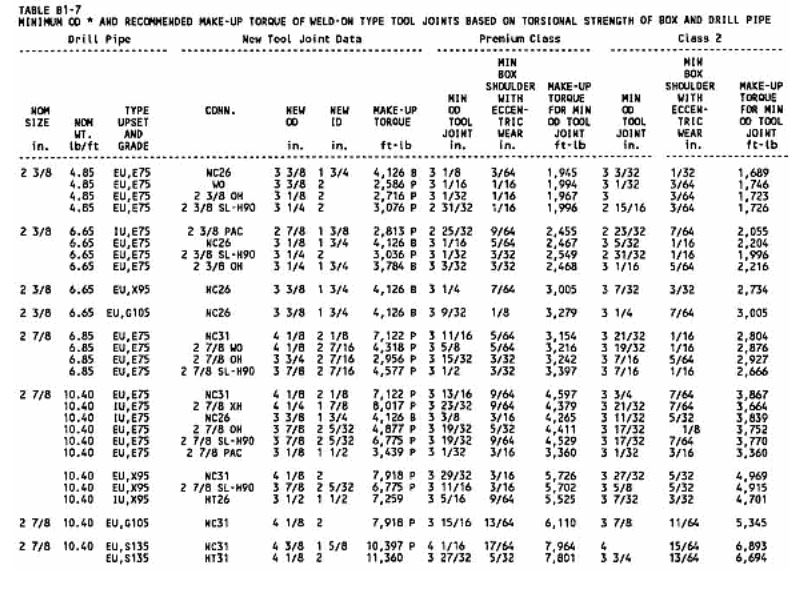
Notes on Table 4
- The use of outside diameters (OD) smaller than those listed in the table may be acceptable on slim hole (SH) tool joints due to special service requirements.
- Tool joint with dimensions shown has a lower torsional yield ratio than the 0.80 which is generally used.
- Recommended make-up torque is based on 72,000 psi stress.
- In the calculation of torsional strengths of tool joints, both new and worn, the bevels of the tool joint shoulders are disregarded. This thickness measurement should be made in the plane of the face from the I.D. of the counterbore to the outside diameter of the box, disregarding the bevels.
Tool joint diameters specified are required to retain torsional strength in the tool joint comparable to the torsional strength of the attached drill pipe. These should be adequate for all service. Tool joints with torsional strengths considerably below that of the drill pipe may be adequate for much drilling service.
Drill Pipe Inspection Classification Marking
A permanent mark or marks signifying the classification of the pipe (for example, refer to Table 1, Note 1) should be stamped:
- On the 35-degree sloping shoulder of the tool joint pin (or on the 18-degree sloping shoulder of the pin, if the 18-degree angle is furnished).
- On the end of the tool joint pin on flush OD drill pipe.
- Or in some other low-stressed section of the tool joint where the marking will normally carry through operations. d. Cold steel stenciling should be avoided on the outer surface of drill pipe tubes.