Foamed cement is a coarse dispersion of a base cement slurry, a gas (usually nitrogen), a foaming surfactant, and other materials to provide foam stability.
- The base cement slurry is usually a conventional 15–16 lbm/gal [1,800–1,920 kg/m 3 ] system.
- The density of nitrogen is, for all practical purposes, 0 lbm/gal.
Foamed cement is generally less expensive than systems containing glass microspheres or cenospheres (Edmondson and Benge, 1983); however, special equipment is required at the well site to inject nitrogen or air into the base slurry. Foamed cement can be mixed at lower densities than conventional microsphere systems and yet maintain acceptable properties.
Montman et al. (1982) reported useful properties at densities as low as 3.5 lbm/gal [0.420 kg/m 3 ]. Slaton (1981) reported the use of foamed cement at densities as low as 5.0 lbm/gal [600 kg/m 3 ] in situations in which compressive strength and permeability were not critical.
Montman et al. (1982)
Foamed Cement Applications
Foamed cement has several advantages in addition to its low density:
- Relatively high compressive strength developed in a reasonable time.
- Less damaging to water-sensitive formations.
- Lower chance of annular gas flow.
- Ability to cement past zones experiencing total circulation losses.
- Also, because the gas has little effect on placement properties such as thickening time, the system density can be adjusted during the cement job by simply changing the gas concentration.
- The low density of foamed cement reduces losses to potential producing zones, and increased well productivity may result.
More recent applications of foamed cement include controlling shallow flows below the mud line in deepwater wells, deterring compaction damage in soft formations, and resisting damage from external stresses placed on the cement sheath.
Understanding Foamed Cement Stability & Structure
The foaming agent, the quantity of gas, the chemical and physical composition of the slurry, thermodynamic factors, and the mixing method and conditions affect the stability of foamed cement. Stable foams exhibit spherical, discrete, disconnected pore structures with a clearly defined cement matrix. Unstable foams have nonspherical and interconnected pores caused by the rupture and coalescence of gas bubbles. Such unstable foams have sponge-like structures and develop lower compressive strength, permeability, and inferior bonding properties.
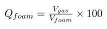
Foams are categorized by their quality (Q foam), or the ratio of the volume occupied by the gas to the total volume of the foam (expressed as a percentage) (Eq. 1).
As the foam quality varies, two structural situations occur.
- Concentrated foams are mostly gas phases and consist of polyhedral gas cells separated by thin liquid films.
- Dilute foams consist of nearly spherical bubbles separated by thick liquid films. This Foamed cement has a quality not exceeding 80% and usually less than 50%.
Compressibility
Foamed cement is a compressible fluid; consequently, due to hydrostatic-pressure variations, the foam quality and density change as the foam circulates in the well.
- Q foam decreases, and density increases as the foam moves from the surface to the bottom of the casing.
- As the foam moves back up the annulus, Qfoam increases, and density decreases.
- The density can be predicted as a first approximation by considering the compressibility laws and the solubility of nitrogen in the base slurry.
Three-Phase System Effect
Foamed cement is a three-phase system (gas /liquid/ solid), with many phenomena occurring at the interfaces. This system is in constant evolution because of the reorganization of gas bubbles that may grow, shrink, or coalesce, and because of the chemical reactions that occur in the base cement slurry. Foams are difficult to characterize because they are shear history-dependent fluids, and their texture is strongly affected by the mixing procedure. Foamed cement made under large-scale field conditions, with high shear rates and high pressure, is more stable than foamed cement made under laboratory conditions (Davies et al., 1981).
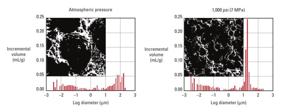
More recently, de Rozières and Ferrière (1991) showed that foamed cement generated in the laboratory at 1,000 psi [7 MPa] is more stable and has a narrower bubble-size distribution than slurries generated at atmospheric pressure (Fig. 1).
Solids & Stability
The solids play a significant role in foam stabilization. When a solid particle adheres to a bubble, it inhibits bubble coalescence and enhances foam stability. The foam stability is related to the size of the particle and its wettability. How solid particles are retained at a liquid/gas interface is analogous to the adsorption of solute molecules. In both cases, work is required to transfer the material off the surface and into the bulk solution.
This work of desorption is the phenomenon that confers thermodynamic stability to the foam. In the case of finely divided solids, Ross (1969) reported that stability is improved by a reduction in the particle size. Also, particle size is significant because it affects the sedimentation rate.
Thermodynamics Properties & Stability
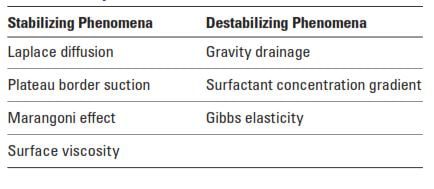
Thermodynamic properties also affect foam stability (de Rozières and Ferrière, 1991). Some of the principal thermodynamic parameters are listed in Table 1.
Preparation Of Foamed Cement On Well Site
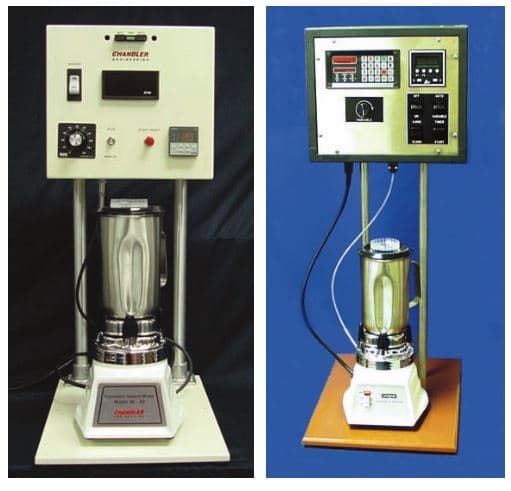
The most common method to prepare foamed cement at the well site is to mix a base cement slurry with all the cement additives except the surfactants and then inject the surfactants and the gas as the slurry is being pumped downhole. In addition to the pressure at which foam is generated, the foam-generating equipment can influence the stability and bubble-size distribution of the foamed cement.
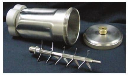
Foamed cement is routinely prepared in the mixing devices depicted in Fig. A. A special multi-blade assembly can also be employed (Fig. B). A base cement slurry containing surfactant is placed in the blending container, the container is capped and sealed, and the mixing device is operated at a high propeller speed until the resulting foam fills the mixer bowl. The foamed cement density and quality are varied by adjusting the volume of the base slurry added to the blending container. The disadvantage of this procedure is that the foam is not prepared under simulated high-pressure field conditions.
Foamed cement design
Early in the development of foamed cementing, suitable base-slurry compositions to prepare foamed cement were limited. Today, with improved surfactants and foam-generating equipment, virtually any base slurry can be foamed.
Cement, Foaming Agents, Stabilizers, and Additives
A stable base slurry is a prerequisite for a stable foamed cement system. The same mechanisms that produce free fluid or solids segregation will contribute to the destabilization of foamed cement.
The selection of the base slurry density depends on the required set-foamed- cement properties. Normal-density base slurries will lead to higher compressive strengths. However, such slurries require larger volumes of gas to achieve a given foam density; therefore, the resulting permeabilities will be higher. Conversely, less dense base slurries (prepared using lightweight filler materials) require less gas and produce foamed cement with lower permeabilities; however, the compressive strengths will be lower.
To select suitable foamers and stabilizers for cement, one should consider the following criteria:
- safety and handling considerations
- compatibility
- effect on the cement strength and permeability
- stability
- efficiency
- cost.
The chemicals used to generate and stabilize the foamed cement must be effective at elevated temperatures and pressures and in a cement slurry’s highly alkaline, calcium-containing aqueous phase. Common foaming agents include ethoxylated alcohols and quaternary ammonium salts of fatty acids. Common stabilizers include polyglycol ethers and sulfate salts that impart some thixotropy to the base slurry.
The duration of foam stability must be longer than the setting time of the base slurry. In addition to the base slurry, foaming agent, stabilizers, and additives, one must use an inert gas with respect to the cement properties (e.g., nitrogen) and a foam generator with sufficient energy and mixing action.
Foamed Cement Properties & Testing
Laboratory testing of foamed cement under simulated downhole conditions is difficult. Because of the pressure and temperature dependence of the foam volume, curing a foamed cement at high pressure and temperature requires different equipment than that used for conventional slurries (Appendix B). Work by de Rozières and Ferrière (1991) showed that varying the pressure and mixing conditions during foam preparation can strongly affect compressive strength and permeability. This is presumably caused by differences in the bubble size distribution of the resulting foam.
Stability
The stability must be tested to ensure the gas will not break out of the slurry. If the gas coalesces and the size of the bubbles increases, gas pockets form and rise in the cement column, resulting in uncemented sections or channels in the well. A simple test to evaluate stability involves slicing a column of set foamed cement into wafers of equal size. The weight of each wafer should be the same in a stable system.
Compressive strength and permeability
When the density of conventional cement slurries is reduced by adding water or other extenders, the amount of cementitious material is diluted. Because of the large density difference between water and gas, much less gas is required to reduce the density by an equal amount. Using gas results in less dilution and less impact on cement properties. Consequently, the physical properties of foamed cement are similar to those of conventional lightweight cement that are 2 to 4 lbm/gal [240 to 480 kg/m 3 ] heavier.
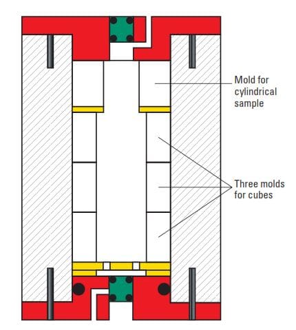
Compressive strength and permeability are frequently tested using slurries containing the same volume percent of the gas that would exist in the slurry under downhole conditions but cured at atmospheric pressure. De Rozières and Ferrière (1991) showed that the results can be misleading, and they developed equipment to generate and cure foamed cement under higher pressures (Figs. 2 & 3).
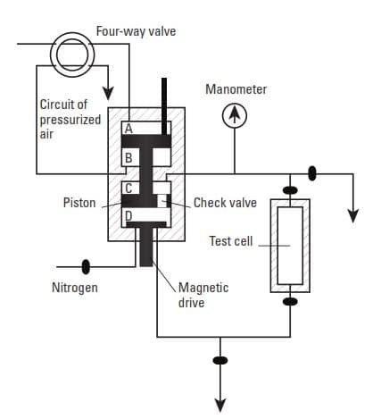
Nitrogen is injected into the lower chamber while the base slurry is pumped through the mixing chamber and the test-cell loop to generate foamed cement.
Nitrogen is injected until the desired test pressure is attained. The foam quality is determined by the ratio of slurry to the total volume in the circulating loop. The test cell can be used to cure specimens for testing compressive strength, permeability, or other properties. The foamed cement slurry can also be injected into a fluid-loss cell.
Mechanical properties
Foamed cement has a lower Young’s modulus than conventional cement. One must add large amounts of water to achieve a lower Young’s modulus with conventional cement, resulting in lower compressive strength. With foamed cement, the impact on compressive strength is lower. Cement with lower Young’s moduli is less susceptible to failure when exposed to the common mechanical stresses associated with well operations.
Shear bond
Davies et al. (1981) reported that foamed cement can undergo a bulk expansion before setting. In some situations, this can result in improved bonding (Slaton, 1981). 3
This hypothesis is supported by indirect evidence from the improved cement bond logs obtained from wells cemented with foamed cement and can be explained as an effect of pressure maintenance by the compressed gas in the cement. As the cement loses hydrostatic pressure during gelation, the gas pressure maintains tight contact between the cement and the casing or formation.
Thickening time
Among the tests performed on foamed cement, thickening time is the most difficult to perform and the least conclusive. To be valid, this test should be performed under simulated downhole conditions, and the foam should be mixed in a manner comparable to what occurs on location. Thus, the slurry should ideally be prepared in a pressurized mixer and transferred under pressure to the pressurized consistometer. The thickening time test involves measuring the evolution of slurry viscosity. Because of the particular rheological behavior of foam, the shear field in the consistometer is not uniform. A large part of the foam remains static, while the small amount that is sheared is destabilized.
Instead of testing foamed systems, a common procedure is to measure the thickening time of the base slurry containing the additives, surfactants, and stabilizers. This method gives a reasonable estimate of the working time for the foamed slurry.
Fluid loss
Introducing a gas to a liquid medium significantly reduces the rate at which the liquid will flow through porous media.
Thermal and electrical conductivity
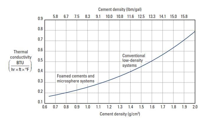
Short et al. (1961) reported that foams have lower thermal conductivity because of the presence of gas voids and the lower amount of solids. Nelson (1986) reported that the thermal conductivity of cement systems is roughly proportional to slurry density, regardless of whether the cement was foamed. These data are presented in Fig. 4.
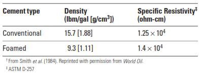
Studies of the resistivity of foamed cement indicate that the electrical conductivity is similar to that of conventional cement (Table 2).
Rheology
The rheological behavior of foams is unlike that of other fluids. The differences arise from many factors. Foams are compressible fluids; they are heterogeneous and have variable properties under shear. Foams are dynamically unstable, shear-history-dependent fluids in which the bubble structure is continuously destroyed and rebuilt. For these reasons, rotational viscometers with a fixed amount of sample are unsuitable. The rotational shear disturbs the bubble network, often resulting in foam collapse.
Continuous flow-tube viscometers are more suitable for testing foams even though foams are compressible, are non-Newtonian, and will never attain a steady state. Viscosity, density, and flow rate will vary continuously as the system pressure changes along the tube. As a result, the equations to calculate shear stress and the shear rate at the wall require corrections. In addition, low-pressure viscosity measurements of foamed cement may not be representative of field conditions. Such problems are minimized if tests are performed at the pressures encountered in the well and at low differential pressure.
To the best of the authors’ knowledge, no routine rheological measurement is made on foamed cement slurries. However, visual observations of foamed cement flowing in plastic tubes have shown that, at low flow rates, the foams flow as a rigid plug, moving on a thin film of water next to the wall (Princen, 1982).
Calculations for Foamed Cement Jobs
Most cementing companies in oil and gas use computer programs to design foamed cement jobs; however, it is useful to know how to perform the calculations manually. As discussed in Chapter 7, foamed cement jobs can be divided into two types (depending on the method of scheduling the gas phase): constant nitrogen (or air) ratio and constant density. During a constant-nitrogen-ratio job, the nitrogen is added to the base cement slurry at a constant rate (standard cubic feet [scf]/bbl of slurry). Because of compression, this method results in cement with variable density—lightest at the top, heaviest at the bottom.
A constant-density job is one in which several stages of foamed cement, each with a different volume ratio of nitrogen to slurry, are used. The nitrogen-to-slurry ratios are calculated so that each stage will have the same average density at its final position in the annulus; however, the density varies within each stage because of differences in hydrostatic pressure within the stage. In this section, the design calculations for the constant-density method are presented. The same calculations may be used to design a constant-rate job. In that case, the entire interval is considered as one stage.
The following items are calculated to design a foamed cement job.
- Minimum fracture pressure (less a safety factor) and location
- The hydrostatic pressure of the fluids above the weak zone(s) (if the tail slurry is above the weak zone, it must be included)
- The allowable average density of the foamed cement (to meet the fracture-pressure limitation)
- Number of stages
- Hydrostatic pressure at the midpoint of each stage
- Nitrogen requirement for each stage based on the midpoint hydrostatic pressure
- Foam quality (or gas ratio) for each stage
- The yield of the foamed cement for each stage
- The volume of each stage (from length of stage and caliper log)
- Hydrostatic pressure as each successive stage of foamed cement enters the annulus (this is necessary because the gas ratio of the first stages of foamed cement is lower at greater depths owing to gas compression; thus, their density as they pass the shoe will be higher)
- Pump schedule including
- base slurry volume
- nitrogen ratio
- nitrogen volume
- nitrogen pump rate
- foamer pump rate
Once these calculations are made, a series of tables and graphs should be constructed to show the parameters for each stage. The following example illustrates this procedure.
I have created a small PDF from the great cementing book “Well Cementing Second Edition Editors Erik B. Nelson and Dominique Guillot” that contains an example of the foamed cement calculations steps. You can download it from the below link.
Actual Reports & Lab Activities on Foamed Cement
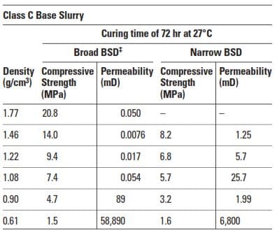
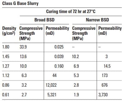
Starting with normal-density Class C and Class G cement base slurries, de Rozières and Ferriere (1991) prepared foamed cement and determined the compressive strengths after curing them 72 hr at 80°F [27°C]. Foams with broad and narrow bubble-size distributions were generated from each base slurry. The results in Table 2 clearly show the benefits of having a broad bubble-size distribution.
A broad bubble-size distribution leads to higher compressive strength throughout the slurry-density range. The effect of bubble-size distribution is less clear. At densities above about 1.0 g/cm3, foams with broad bubble-size distributions have lower permeabilities. At densities below about 1.0 g/cm3, foams with a narrow bubble-size distribution have lower permeabilities.
Chekiri (1978) reported that perforation of foamed cement with qualities above 40% tends to cause excessive fracturing. As a rule, the permeability also increases dramatically when the quality exceeds 40%; however, this depends on the additives, type of foamer, and curing conditions (Aldrich and Mitchell, 1975; Smith et al., 1984).
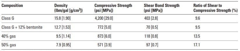
Smith et al. (1984) reported that foamed cement at 7.9 lbm/gal [948 kg/m 3 ] develops higher shear-bond strength than a 12% bentonite cement at 12.7 lbm/gal [1,520 kg/m 3 ]. They also found that the shear bond to compressive strength ratio is higher for foamed cement and increases with nitrogen concentration. These data are presented in Table 3.
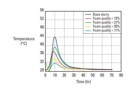
Calorimetry experiments performed under static conditions at atmospheric pressure showed that the foam quality does not influence the hydration kinetics (de Rozières and Ferrière, 1991) (Fig. 5). A calorimetric thermogram is not equivalent to the thickening time. These results only demonstrate that the cement hydration process is not affected by the presence of gas in the system.
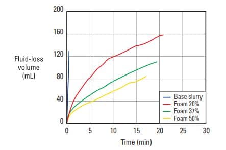
De Rozières and Ferrière (1991) evaluated foamed cement, with and without fluid-loss additives, and found that the fluid-loss rates were lower when gas was present (Fig. 6).
While studying foamed fracturing fluids, Harris and Reidenbach (1987) found that the bubbles tend to reach a small, uniform size at high energy levels. The bubbles coalesce and drain at low energy levels, forming large nonuniform bubbles. Harris and Reidenbach also observed that the frictional pressure drop for foamed fluids can increase twofold from when a foam is created until equilibrium is reached.
References:
- Well Cementing Second Edition Editors Erik B. Nelson and Dominique Guillot
- Foam Cement Technology Solves Lost Circulation Problem D. L. Bour, SPE, Halliburton Energy Services, Inc.; R. Mohan, SPE, Halliburton Trinidad, Ltd.; T. Baumbach, SPE, Schlumberger Trinidad, Inc.; B. Schofield, SPE, Amoco EPTG Drilling, Amoco Trinidad Oil Co.; and G.G. Plus, SPE, formerly Amoco EPTG Drilling, Amoco Trinidad Oil Co.
- Foam Cement Technology Foam Cementing Cyclic-Steam, Producing Wells: Cymric Field Case Study Larry S. Miller, SPE, Halliburton Energy Services, Inc. and William E. Frank, SPE, Chevron U.S.A.