In this article, we will highlight the basic equipment and techniques that are used at the well site by the mud logging unit to provide the basic surface logging services.

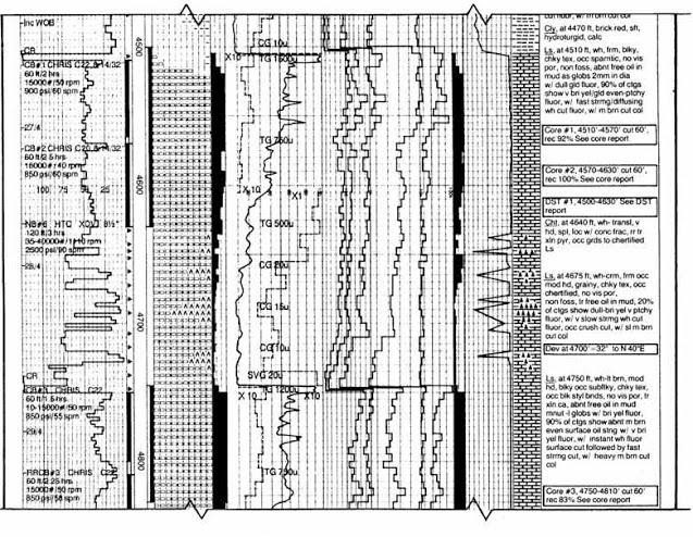
Formation Evaluation Log
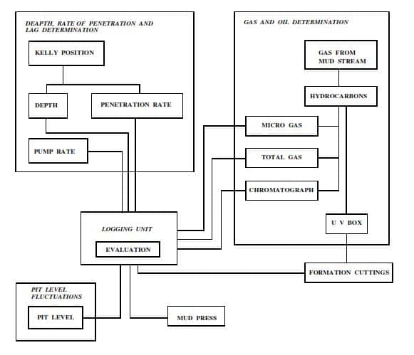
The surface mud logging unit is not complex in principle, does not interfere with the drilling process, and the results are available almost immediately. The Formation Evaluation Log (Figure 1) is recorded simultaneously with the drilling of the hole. Detailed data on the physical characteristics of the subsurface strata is collected and analyzed as it becomes accessible at the surface.
This information is continuously evaluated and control of certain phases of the drilling operation is exercised by the operator based on the interpretation of the results. Besides almost immediately indicating the presence of any potentially productive zone, the Formation Evaluation Log serves as a basis for modifying the drilling program to ensure a safe and cost-efficient program. It is also an important corroborative and correlative tool.
What does Formation Evaluation Log contain?
A comprehensive Formation Evaluation Log contains the following information:
- Total combustible hydrocarbon gases from the drilling fluid
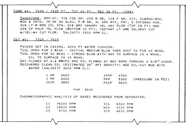
- Chromatographic analysis of the total gas for individual gas content (methane to pentane) in ppm
- Total combustible gas from drill cuttings
- Oil from drilling fluid and drill cuttings
- Detailed rate of penetration curve
- Lithologic composition and description (including estimated visual porosity)
- Drilling fluid characteristics
- Data are pertinent to the well’s operation, such as coring points, casing points, trips for a new drilling bit, drill stem tests, etc.
- Bit data, carbide lag information, borehole deviations, and other pertinent engineering information
- Hydrocarbon show reports, conventional and sidewall core reports, and test reports
Depth & Drill Rate Determination in Mud Logging Unit Equipment
The depth and drill rate are available simultaneously while drilling an interval of hole. This “real-time” information can also be the first indication of borehole problems or show intervals. The rest of the subsurface data pertaining to the interval is not available until returns from that interval are pumped to the surface. The “lagged” information is then correlated with the “real-time” information over the “logging interval”.
This interval is usually every 5 or 10 feet (1 to 3 meters), meaning that all data concerning the well is collected or determined for each interval as the well is drilled. Depth is recorded in feet or meters, while drill rates (see also factors affecting penetration rates) are recorded in terms of distance per unit time (feet/hour, meters/hour) or time per unit distance (minutes/foot, minutes/meter).
Visit Depth & Drilling Rate Determination By Mud Logging for more information.
Lag Time Determintion
Lag time is the time required for the cuttings resulting fro drilling to reach the surface. In lag time determination article, we have discussed its importance and how mud logging unit can determine the actual lag time.
Gas Chromatography
A chromatograph separates and analyzes hydrocarbons in the ditch gas sample to determine how much of each hydrocarbon is contained in the sample. In Mud Logging Gas Chromatography article we will handle both methods used by mud logging unit equipment.
Gas While Drilling Determination
While drilling there are some gases released from the formation that is drilled and get entrained in both mud and cuttings. In Gas While Drilling Determination Article, you will learn how mud logging unit equipment can easily determine such gases.
Microscope In Mud Logging Unit
A binocular microscope with several magnifications is used for lithological evaluation and descriptions.
Ultraviolet-Light Box
This instrument is used for determining the percentage, physical character, color, and intensity of hydrocarbon fluorescence in drilling fluid and cuttings. It consists of a box with a viewer on the top, containing ultra-violet tubes and white light bulbs. The 3600Å, long ultraviolet source used by INTEQ is effective in producing fluorescence in the visible region since it is itself on the threshold of visibility. The detachable top and large doors allow the UV box to be used for core analysis.
Mud Press
Mud filtrate and filter cake are significant properties of the drilling fluid and the filtrate, itself, is used for various chemical analyses. A drilling fluid should deposit a good filter cake on the wall of the hole to consolidate the formation and retard the passage of fluid into the formation. It must also have a minimum “water loss” to avoid clay swelling problems or excessive invasion. To test these properties, it is necessary to determine the rate at which fluid is forced from a filter press and the thickness of the residual solid film deposited on the filter paper by the loss of fluid. A number of tests can be conducted on the filtrate, including the determination of resistivity, chloride content, and nitrate ion content as indicated below:
1. Resistivity from Filtrate – the resistivity of the filtrate may be measured periodically during the course of drilling and later used for interpretation of MWD and wireline log resistivity curves. More commonly, however, the resistivity test is conducted on a sample of the mud from the hole prior to running a suite of wireline logs. A portable resistivity meter is usually available to conduct this test.
2. Chloride Content from Filtrate in Mud Logging Unit- the salt or chloride test is very significant in areas where salt can contaminate the drilling fluid. (This would include the majority of the world’s oilfields). The salt may come from make-up water, salt stringers or beds, or from saltwater flows.
3. Nitrate Ion Test – water recovered from a formation or drill stem test cannot always be identified as invasion filtrate or natural connate. The usual method is to determine the salinity (or resistivity) of the recovered water and compare it to the salinity (or resistivity) of the mud filtrate from a mud filter press. However, n some areas and in some circumstances, the salinity of the naturally occurring formation (connate) water may be indistinguishable from that of the mud filtrate. Tests on the composition of formation waters have shown that the natural occurrence of the nitrate ion (NO ) is very rare – in fact, almost unknown. Therefore, if nitrate ions are added to the mud, the filtrate will contain nitrate ions and carry them into the formation during the invasion. On subsequent tests, if the water recovered contains the same concentration of nitrate ions, the fluid recovered is solely filtrate and not formation fluid. Conversely, if the nitrate ion concentration is reduced, it can be concluded that the dilution was caused by the entry of formation fluids.
4. From this type of mud logging unit information the evaluation of a drill stem or wireline test can be made quickly and confidently at the well site. The methods may also be used upon well completion for determining the oil-water contact and thus, help in setting up production zones.
Pit Level Indicators In Mud Logging Unit
Two types of pit-level indicators are commonly used by Mud logging Unit companies that are working in oil and gas, and both work on the same principle – a float rises or falls with the mud level. This movement is detected by a change in resistance in the electrical current from the sensor to the logging unit. The basic pit-level indicator consists of a float on the end of an “arm” in the mud pit, attached to a variable resistor enclosed in an oil-filled housing. The pit level is recorded on a chart with as great a span as possible, assuring maximum sensitivity so that changes in level are immediately recognized. With this system, usually, only one (the active) pit is monitored.
Today it is common to monitor more than one pit. Using microprocessor-based Pit Volume Totalizers (PVTs), up to 20 pits can be monitored. As with the basic Pit Level Indicator, the PVT is used to detect any fluctuation in mud volume caused by fluid losses or gains. Transfer of mud between pits does not affect the total pit volume reading, but any significant loss or gain to the pit system causes a change in the reading.
The PVT also provides information as to available mud, which can assist in the maintenance of the mud system during normal drilling. The total-pit volume reading, displayed on a panel meter in digital form, is continuously recorded on a chart recorder and can be multiplexed to a computer. The volume of a pit is determined by using vertical float-actuated sensors to measure the mud level in the pit. The microprocessor can also monitor the rate of change in each pit as well as the system as a whole. Alarms on each pit, as well as the total volume, add to the effectiveness of monitoring.
Pump Stroke Sensors In Mud Logging Unit
Pump stroke counters are used in mud logging units to monitor all active mud pumps, primarily for correct lagging of samples to the surface. Usually, the sensor consists of either a “micro-switch” or a proximity switch attached to the mud pump, which is tripped by the action of the pump’s rod. The pump stroke panel includes a flashing light, synchronized with the sensor, a digital counter for each pump, and a stroke per minute (spm) meter. These advance by one each time a cycle is made by the mud pump(s).