This stage of the Cementing in drilling process comprises the slurry preparation and pumping equipment at the surface and the down-hole hardware. A vast array of equipment and tools are available from specialized manufacturers and Service Companies and a brief description of the various items, to explain their purpose and function in the cementing processes and operations, is provided in this chapter. Detailed information is readily available from the cementing operator and in the public domain.
Surface Cementing Equipment
In most operations, the surface equipment for blending and pumping cement slurry belongs to a Cement Service Company, contracted to provide this service. The layout of the hardware varies, but in general, will include the following items.
- Cement Transport, Handling & Storage
- Mixing and Pumping Equipment
- Cementing Additive dosing
- Cementing Units
Cement Transport, Handling & Storage Equipment
Dry cement is transported from the supplier or Service Company yard to the oil and gas company premises or directly to the well-site by road, rail, or carried on a supply boat for off-shore operations. On-site the cement is stored either in bulk silos, big bags, or sacks.
Bulk Silos
Bulk silos come in various sizes and shapes, depending on whether part of a stationary installation or a mobile unit and available space. The fairly standard size is 38 m3 (1350 cubic feet), also frequently used for other bulk commodities such as bentonite and barite. The silos are fitted with nozzles for blowing air to ‘fluidize’ the dry material and some arrangements to gauge the contents, for example, a load cell. A man-hole at the top allows visual checking of the contents as well as recovery of a sample. However, it is preferred to take the latter from the transport line or manifold during transfers, through a special proportioning device to collect a representative sample. For dry-blending operations, a “weighing” silo of small capacity mounted on a weighing device is required.
When tanks are topped up a representative sample should be taken from the tank after “fluffing-up” to homogenize its contents.
Bulk storage is generally considered to offer operational convenience over the other two alternatives. It requires compressed air to move the dry powder and manifolding to allow movements between silos. Care should be taken to use dry air for the pneumatic transport to avoid lumps of cement blocking lines. For offshore rig operations, this mode of handling cement is nearly universal, although in a few cases big bags are used. A further point to note is avoidance of cross-contamination from other bulk materials (barite, bentonite).
Cement Sacks
Cement in sacks needs to be cut near the mixing tools facility, making for a rather messy operation. The occupational health and environmental/waste aspects of this cement handling mode should be weighed against the convenience and cost considerations. In general, it is advised to use bulking facilities wherever possible. A standard cement sack contains 42.6 kg (94 lbs) of cement or 0.028 m3 (1 cubic foot) bulk volume, although a metric equivalent of 50 kg is increasingly becoming available.
Big Bags
Big bags, containing up to 1.5 tonnes of cement, have to be lifted and positioned above the tub of a jet mixer or the hopper for a recirculation mixer. Occupational Health and environmenta1/waste implications are significantly lower than in the case of ordinary sacks. Big bags also offer a higher degree of flexibility compared to sacks and do not require the (high) investment of bulking facilities. Party-used bags should be resealed and stored in a dry place. Big bags are recommended where bulking facilities are not available in preference over sacks.
Cementing Mixing and Pumping Equipment
The preparation of a slurry is done by blending the cement with the mix water exerting sufficient shear to disperse particles and to promote proper yielding into a homogeneous mass. The blending is done in the cementing unit. This can be a (semi)-permanently installed facility on off-shore rigs or a mobile one called in for the job.
Cementing Pumps
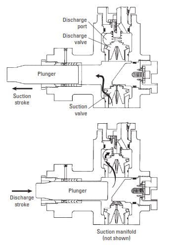
A cementing unit includes various pumps to move slurry between stages.
- centrifugal pump(s) for recirculation mixing. Centrifugal pumps are mostly electrically driven units, typically rated at 56 kW (75 HP).
- High-pressure displacement pumps. These are most commonly of the triplex variety, either driven by a diesel engine or electrically powered. The standard cementing skid is configured for two pumps, each typically rated at 172 kW (230 HP). The units are capable of delivering between 0.6 -and 1.65 m3/min of cement slurry at pressures ranging from 102 to 37 MPa (15000 to 5500 psi) depending on the plunger tool size.
Slurry transport
The slurry prepared in the cementing unit is usually pumped to the casing head through a temporary connection made up with Chicksans. In some operations, a permanent line is installed to connect the cementing unit with the stand-pipe manifold on the drill floor. The connection to the cementing head is made through a short length of high-pressure hose or made up with Chicksan joints. Secondary or remedial cementing is usually carried out through drill pipe and cementing stinger or coiled tubing. In this case, the slurry is delivered to the stand-pipe manifold or CT unit, either through a temporary connection or a dedicated delivery line.
Cementing Units
Cementing unit Equipment is designed for pumping cement into the well. They are used for drilling, workover, and killing well operations (driller’s method – wait and weight method). In Cementing Units article, we have discussed its main components and types.
The main components of the cementing unit:
- Storage Bulk Tanks
- Cement Pump.
- Liquid additive storage and mixing
- Surge tanks
- Cement Mixer
Cementing Unit Types
- Skid-mounted units
- Truck Mounted Units
- Semitrailer-mounted units
- Helicopter Units
- Single Pump Cementing Unit
Downhole & Surface Cementing Tools
The choice between the types of casing and casing sizes to be run and cemented is dictated by the well design and therefore outside the scope of this article. However, to improve the chances of achieving successful primary cementation several items of auxiliary equipment are incorporated in the string.
Float Equipment
These cementing tools are usually placed two joints above the shoe. Sometimes the float collar is combined in a float shoe. Its purpose is that of a check valve preventing backflow after the cement has been placed in the annulus and retaining the cement interface inside to ensure good cement around shoe. This is done most of the time by a spring-loaded ball or flapper suitably seated to seal.
Cementing Head Tool
After running and setting in the rotary table slips, a cementing head is mounted on top of the casing. This tool also contains one or more plugs to separate cement, pre-flushes) etc., from mud before and after pumping/displacement. The plugs are retained in the cementing head by pins or bars, which are pulled out at the appropriate time to release the plug, or bails, which are rotated to drop a plug. Plugs are moved by switching to the appropriate fluid connections on the head.
Cementing Plugs
Plugs available from cementing service companies come in a variety of shapes and sizes. The selection of plug(s) for a particular job should be guided by local experience. One feature to be considered is the rotation of plugs when drilling out. Nowadays plugs (and floats) are available that have been manufactured with a serrated top and or bottom profile, permitting the plugs to lock when seated.
Casing Centralizers
Centralisers Positioning of the casing as close as possible to a concentric configuration undoubtedly will enhance displacement of the annular contents. Bore-holes very seldom exhibit the much desired ‘gun barrel’ shape and smoothness. Most of the time the holes are corrugated with wash-outs and ledges and have a more or less elliptical cross-section. This is particularly true for directional drilling. Running a casing in these holes, without auxiliary equipment to correct for its shape, invariably results in sagging of the casing to one side.
This will increase the danger of the casing getting differentially stuck ( check also free point calculation for stuck pipe). Centralizers are used to center the casing in the bore-hole as closely as is possible and to increase the stand-off, defined as the eccentricity divided by the radius difference between casing OD and hole.
Cementing Scratchers Tools
Less popular, scratchers can be installed to scrape excessive mud cake deposited over permeable hole sections. These accessories are attached between stop rings, allowing a certain amount of ‘travel’ during reciprocation of pipe in the cementing stage. The wire and cable types are most commonly used. The design differs according to the casing cementing mode, i.e. whether or not movement (rotation/reciprocation) is exercised during cement displacement and/or prior circulation.
Guide Shoe
The shoe is the leading edge of the casing (or casing liner). The purpose of this cementing tool is to ease the passage of the pipe through the previous casing and the open hole section beneath. To this end, the shoe has been given a rounded shape. It is (partly) made of molded cement insert or cast aluminum to facilitate drilling out for the next hole section. The shoe comes in various shapes and can be obtained from Cementing Service Companies.
Stage Collars For Casing & Liners
Multi-stage cementing may be necessary where circulation losses would prevent cement from reaching the required depth or the hydrostatic pressure from the fluid column above a weak zone would induce fracturing and/or losses. Multi-stage cementing requires the incorporation of tools such as stage or port collars in the casing string, to provide selectable access to the annulus.
Cement Stinger Tools
Cement stinger is used in special cases ad cementing large-diameter casings, set cement plugs in which drill pipe is placed inside the casing as the conduit for pumping fluids from the surface to the casing annulus.
Cement Retainers
Permanent packers, (one of the types of packers) also referred to as ‘cement retainers’, are available from several Service Companies (Baker Model K and Dowell Schlumberger Johnston Hornet are examples). These tools have a check-valve function, to prevent backflow, which is activated when the cement stinger or tubing is pulled back.
Cementing Tools – External Casing Packer
These inflatable devices are often used instead of a cement basket in multi- stage cementing. ACPs are strictly pack-off devices and their main attraction is the protection of weak formations below a stage cementing tool against excessive hydrostatic pressure or contamination. They are also used to prevent gas or fluid migration and have the further advantage of contributing to casing centralization.
References For Cementing Equipment & Tools
- Well Cementing Manual – W.J. van Beest – May 1994
- Well Cementing Second Edition Editors Erik B. Nelson and Dominique Guillot