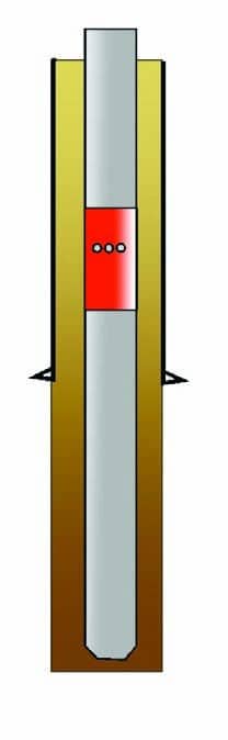
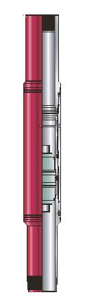
Stage cementing tool, consisting of stage collars and port collars, is placed within any types of casing string to provide an intermediate passage to the annulus (Fig. 1). The collars are generally made of match-grade steel. They may be available in special weight ranges to optimize strength and internal dimensions.
Stage cementing tool is generally used to:
- Protect weak formations from excessive hydrostatic pressure
- Cement widely separated zones
- Reduce mud contamination from cement.
Stage collars are available in both mechanical and hydraulic versions. However, even the mechanical method of opening and closing requires hydraulic force.
Mechanical tools are opened and closed using freefall plugs or pumpdown-closing plugs to select and shift the appropriate internal sleeve(s) (Fig. 2). The lower sleeve initially covers the ports. Once the first stage is complete, the lower sleeve is pumped down to uncover the ports by seating the free-fall (or pump-down) opening plug and applying pressure. The second stage is pumped and the ports are closed again by seating and applying pressure to the larger closing plug. Once closed, the stage collar cannot be reopened. The pressure required to open and close varies with manufacturers, but it is generally between 800 and 1,400 psi [5.5 to 9.7 MPa]. When two-stage collars are used, a special upper stage collar is required, and care should be taken to release the correct plugs in the proper sequence. The ID of the upper stage collar seats must be larger than the lower collar seats. For highly deviated holes, the free-fall dart should be replaced with a pump-down plug. Drilling is required to remove the plugs and aluminum seats.
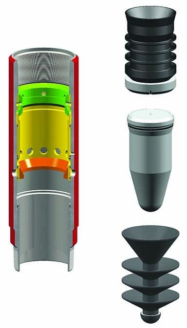
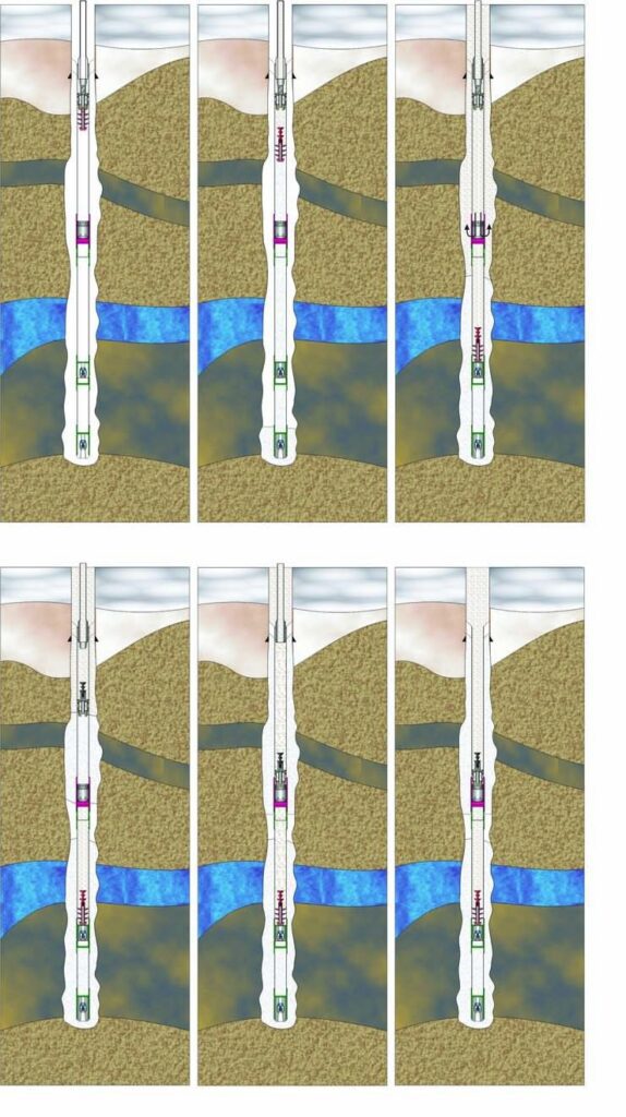
Mechanical stage Cementing tool shown in run-in, open, and closed positions
Figures 3, 4 & 5 shows the mechanical stage tool in the run-in position, the opened position, and the closed position. Figures 6 & 7 shows the plugs and opening devices used to operate the stage tool. As a rule, all stage tools should be opened as soon as the primary job is completed, because any cement slurry above the tool can be circulated out.
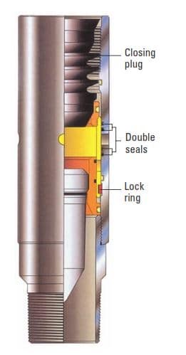
Running position Pin and box threads are identical to the casing threads. Stage collar integral connection is designed for gas tightness. Seals on the opening sleeve provide internal and external pressure integrity across the fluid ports.
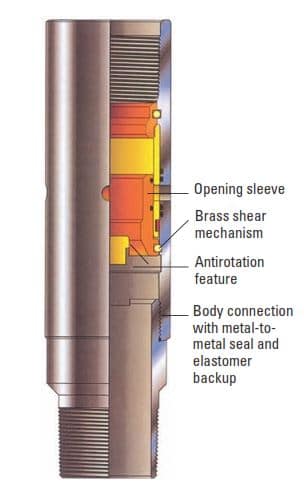
Opened position Opening device has landed and, after pressure is applied, the lower set of shear mechanisms is broken and the sleeve shifts downward to uncover the fluid ports. Pumping operations can now be conducted through the stage collar.
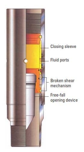
Closed position The closing plug has landed and, after pressure is applied, the upper set of shear mechanisms is broken and the sleeve shifts downward, shutting off the fluid ports. Double seals above and below the ports provide pressure integrity.
Two-stage using a first-stage sealing plug, free-fall opening device, and closing plug
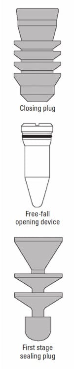
- A float shoe, float collar, and stage collar are installed in the casing string and the casing is run to bottom.
- Circulation is established and first-stage cement is mixed and pumped.
- The first-stage sealing plug is launched and the cement is displaced. At the conclusion of displacement, the first-stage sealing plug lands and effects a seal against the float collar. No baffle is required.
- The free-fall opening device is dropped and allowed to gravitate to position. Pressure is applied to the casing and the stage collar is opened.
- Circulation is established and second-stage cement is mixed and pumped.
- The closing plug is launched and cement is displaced. At the conclusion of displacement, the closing plug lands and effects a seal in the stage collar. Pressure is applied to the casing and the stage collar is closed.
Two-stage using a bypass plug, shutoff plug and baffle, free-fall opening device, and closing plug
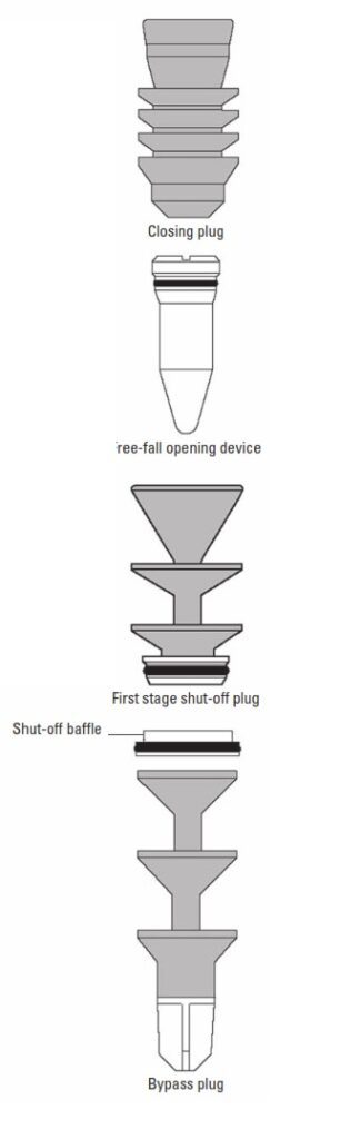
- A float shoe, float collar, and stage collar are installed in the casing string and the casing is run to bottom. The shutoff baffle is installed in the casing string at least one joint above the float collar. If API threads are run (8-rd or buttress) the baffle can be installed in the “J” section of a coupling. If premium threads are run, a separate baffle collar must be run.
- After the hole is conditioned, the bypass plug with the nose piece is launched ahead of first-stage cement. This plug will pass through the shutoff baffle and land on any manual- or self-fill float collar. Once landed, approximately 50 psi will invert the wipers on the bypass plug and allow cement to pass.
- After cement is mixed and pumped, the shutoff plug is launched and cement is displaced. At the conclusion of displacement, the shutoff plug lands and effects a seal in the shutoff baffle.
- The opening of the stage collar and the ensuing second-stage cementing closing of the stage collar are carried out identically to that described for two-stage cementing with first-stage sealing plug.
One of the most common causes of stage tool failure is the inability to close the tool. The correct pressure to close most tools is related to the lift pressure of the second-stage cement column plus the shear strength of the pins holding the sleeve open. For example, suppose an operator is displacing second-stage cement before the closing plug bumps at 600 psi [4.1 MPa]. If the tool is set to close at 1,200 psi [8.3 MPa], then the pump pressure should be raised to at least 1,800 psi (1,200 + 600 = 1,800 psi [12.4 MPa]).
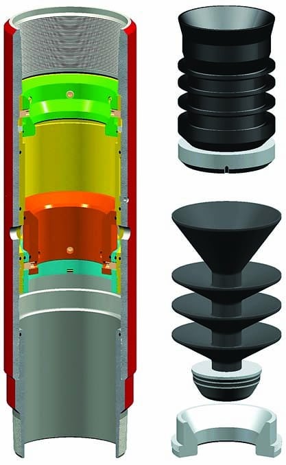
Hydraulic stage tools do not require a free-fall plug or pump-down plug to open the tool. The tool opens when the shutoff plug bumps against either a float collar or landing collar. Then, the pressure can be increased slowly until it reaches a preset shear-pin rating in the stage-tool opening sleeve. The hydraulic stage tool has an internal sleeve much like the differential sleeve, meaning it has a larger area inside the tool on the upper end than the lower end (visible in Fig. 8 in orange color). This differential area, combined with the increasing pressure, keeps the tool closed until the internal area of the tool is pressurized, usually around 700 to 1,000 psi [4.8 to 6.9 MPa]. During the cementing in drilling process, the cement slurry takes the path of least resistance, following the mud out of the stage tool ports and up the annulus. The operating sequence is shown in Fig. 9.
There are optional methods for opening a hydraulic tool with a free-fall plug, and there are special plugs that can be used to open or close the tool if required. These options are available because some operators run stage tools only as a contingency, and if they do not want to use them, they must be able to close them after the job.
Liner stage tool options
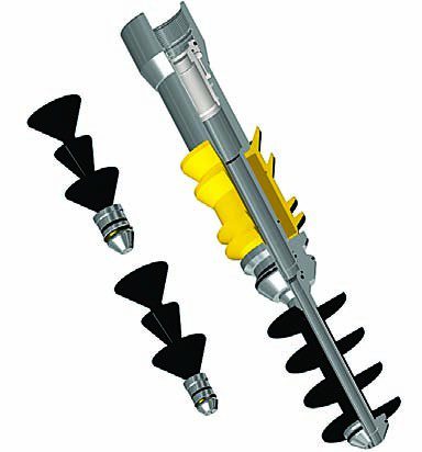
When running stage tools or annular casing packers (ACPs) on casing liners, it is difficult to reliably open and inflate the tool with standard liner wiper plugs. Figure 10 shows a special plug set that works with most liner hanger systems in conjunction with hydraulic stage tools and ACPs. This system is sometimes referred to as a four-plug system, but it is actually two darts and two plugs. The lower dart launches the lower plug and displaces the primary cement, landing on a special plate. Then the pressure builds up, inflating and locking the ACP. Further pressure build-up opens the hydraulic stage tool.
and ACPs
Port collars are another type of stage cementing tool, mechanically operated from the surface by a tool connected to an inner string of drill pipe (Fig. 11). They are available with sliding or rotational valve mechanisms and may be opened or closed as often as necessary. Lock-down options are also available. The sliding valves are generally opened with an upward motion and closed with a downward motion; they require a minimum of 10,000 lbf [44 kN] to stroke. Port collars may be placed as often as necessary in the casing string and selected in any sequence. There are no plugs to use or drill out required. Some shifting tools may be fitted with cup-type seals to form a conduit from the inner string to the ports.
Stage collars and port collars must be handled with care because of the close tolerances between the outer body and the internal sleeves. Tongs or makeup equipment should not be placed in the midbody of a stage collar but rather on the coupling ends, where there are no thin-walled sleeves.
Centralizers and baskets, or annular casing packers (ACPs), are often used with stage cementing tool. Cement baskets or ACPs are placed below the stage collar to help support the hydrostatic pressure of the next stage and to prevent cement from falling through lower-density fluids below.