High-pressure mud pumps are positive displacement pumps. Simply, they convert mechanical power into hydraulic power. Their mechanical components (power ends) are usually maintained by mechanics. However, the drilling crew maintains the pump’s hydraulic part (fluid end). As they are a critical part of the drilling rig equipment, it is mandatory that the drilling engineer should have a thorough knowledge of their mechanical and hydraulic components.
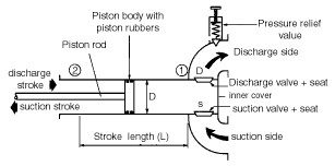
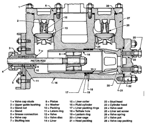
The mud pump nomenclature, as given in Figure 1, showing a cross-section of a duplex pump, should be studied carefully to obtain knowledge of the basic terminology.

In this article, we will deal with:
- Working principles
- General construction
- Pulsation dampeners
- Relief valves
- Capacity, efficiency, and required power
Mud Pump Parts Working Principles
Single Acting Pump
The pump’s power end converts the prime mover’s rotary motion into a reciprocating motion. This reciprocating motion is, in turn, converted to fluid flow by a piston or plunger-type fluid end.
- Crosshead: The mud pump part where rotary motion changes into reciprocating motion
- The Connecting rod: It provides the linkage between the crank and crosshead.
- The piston or plunger: This is connected to the crosshead by the extension rod and the piston rod.
The main parts of the pump’s fluid end are the housing itself, the liners with packing rings, covers plus packing, piston(s) with piston rods, and the suction and discharge valves with seats. (The discharge is normally supported with a pressure relief valve).
The plunger delivers during half the crank cycle only. For this reason, it is called a single-acting pump. We can calculate the delivery of a single piston during one cycle of such a pump as follows ( ignoring losses):
Double Acting Pump
The double-acting piston mud pump is shown in Figure 2. This pump has only two pistons. The suction stroke on one side occurs simultaneously with the discharge stroke on the other. A double-acting pump delivers liquid both during the inward & outward piston strokes. So, comparing it with a single-acting pump having the same piston diameter and stroke, it is clear that the double-acting pump will pump almost twice as much liquid. The output is somewhat less due to the piston rod.
The main parts of the duplex mud pump fluid end are the same as those for the single-acting pump, except for the gland and stuffing box packing on the piston rod side and the additional set of valves per piston.
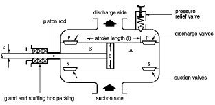
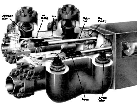
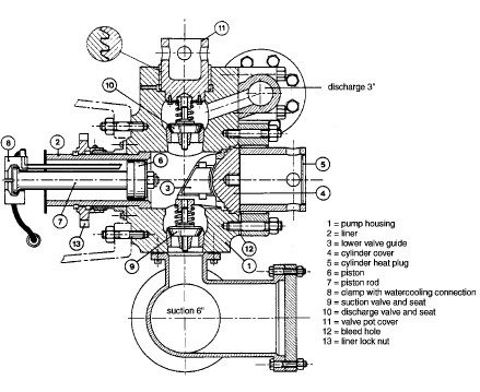
Figure 4 shows the fluid end of a double-acting duplex pump, showing major components.
Applications In Drilling
Both high-pressure mud pumps are utilized on rigs to circulate the drilling fluid around. Each type, however, has its operating limits, which are:
- Duplex pumps: the cranks are at 90°, and the pump can be run at a maximum of 70 spm.
- Triplex pumps: the cranks are at 120° and can be run at a maximum of 150 – 170 spm.
In practice, triplex pumps have the following advantages:
- The triplex pump provides a more even delivery so that discharge variations are about half those of a duplex pump. This provides a longer life for pump parts, hoses, etc.
- The total weight of a triplex pump is approximately 70 % of that of a duplex pump with the same capacity, and it also requires less space.
- Triplex pumps are more accessible than duplex pumps; consequently, maintenance is faster and cheaper.
Downtime incurred due to pump repair is expensive and should be prevented. Frequent pump overhauls are demanding in terms of labor. Therefore, purchasing a generously sized pump is often preferred as this reduces the wear on parts and the required maintenance.
Common operational requirements may vary between 5.4 – 6.7 m3/min at 7,000 kPa (1,200 – 1,500 GPM at 1,000 psi) and 1.35 – 2.25 m3/min at 31,500 kPa (300 – 500 GPM at 4,500 psi). However, from experience, it has been found that the wear of mud pump parts sharply increases when operating the pump at pressures exceeding 21,000 kPa (3,000 psi).
Liner changes can be necessary when the flow rate ranges required during the course of the well cannot be covered by the same liner size, even when several pumps are run simultaneously.
Drilling Mud Pump Parts
The power and fluid ends are shown below in more detail.
Power End
Figure 05 gives a cut-away view of a complete power end. An eccentric shaft converts the rotating motion of a one-piece pinion and shaft into a reciprocating motion. All the shafts are supported by roller bearings.
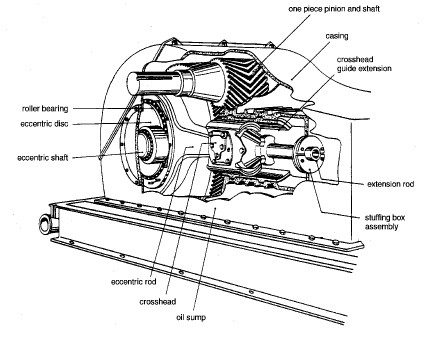
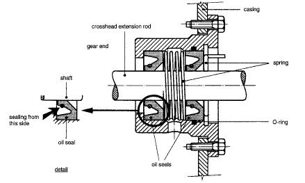
The crosshead, which slides inside a crosshead guide to sustain the true linear movement of the extension rod, is visible, as well as the stuffing box assembly, which is also shown in detail in Figure 6.
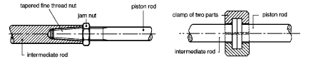
The connection between the extension rod and piston rod is a finely tapered tread with a jam nut (in a double-acting pump) or butted with a clamp (in a single-acting pump), as shown in the figure below.
Fluid End
Figure 8 shows an example of the fluid end of a duplex mud pump.
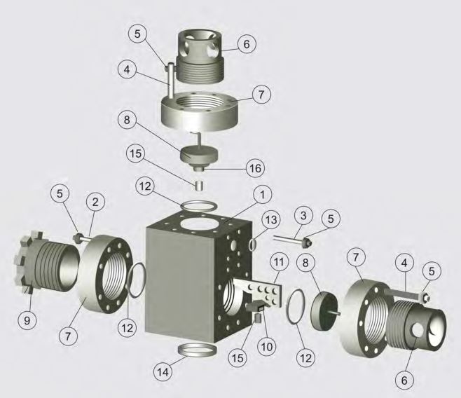
- Item # 1 Fluid Module Only (Studded Included Items 1 – 6)
- Item # 2 Stud – Frame, Threaded Ring
- Item # 3 Stud – Discharge Manifold
- Item # 4 Stud – Threaded Ring
- Item # 5 Threaded Ring
- Item # 6 Discharge Manifold
- Item # 7 Threaded Plug Retainer
- Item # 8 Threaded Ring
- Item # 9 Cylinder Head Plug
- Item # Cylinder Head Plug – Top (Included Items 9 & 17)
- Item # 10 Threaded Liner Retainer
- Item # 11 Lower Valve Guide
- Item # 12 Retainer – Lower Valve Guide
- Item # 13 Seal – Cylinder Head Plug, Liner
- Item # 14 Discharge Manifold
- Item # 15 Seal – Suction Manifold
- Item # 16 Valve Guide Bushing
- Item # 17 Upper Valve Guide
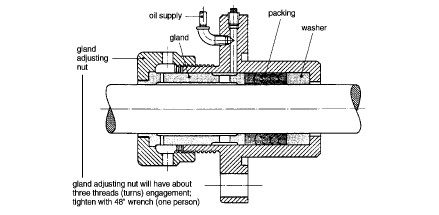
Special attention should be paid to the oil flood stuffing box (Figure 9) to withstand the full pump pressure. The stuffing box is cooled and lubricated by an independent lubricating system.
A closed cooling system protects the pistons of the single-acting pump from overheating (see Figure 10). The cooling liquid is usually a mixture of oil and potable water circulated by a small pump. If the pistons were not cooled, the sleeves would become hot and overheat within a few minutes. The cylinder surface must also be lubricated.
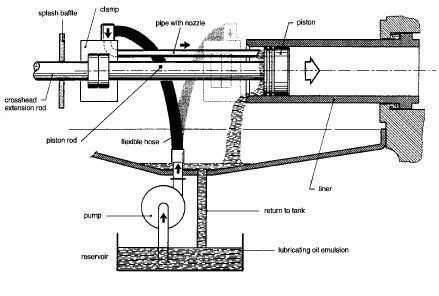
The splash baffle on the extension rod prevents the cooling water from being carried to the pump crank-case by the extension rod.
Piston and Liner
Liners of high-pressure mud pumps are always locked in place by metal-to-metal contact. A special liner lock nut is used in triplex pumps. Duplex pumps are provided with a dual cage metal-to-metal liner retention system (Figure 11).
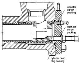
The latter arrangement holds the liner metal-to-metal against a shoulder in the housing utilizing set screws), which are tightened against a liner cage. The liner packing is adjusted separately with set screws on the cage. Some types of pumps have special tell-tale holes (a small hole connecting the liner packing spacer ring area to the atmosphere) to check the proper functioning of the packing. If fluid drips out of these holes, the liner packing has to be tightened. These holes should never be plugged off to stop the “leaking”!
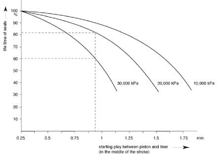
Liner wear is worst in the middle of the stroke because the piston velocity being highest at that point.
The maximum allowable liner wear depends on the pressure the pump has to overcome (see Table 1).
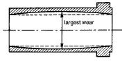
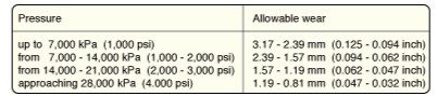
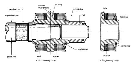
Figure 13 shows the pistons of a double-acting and a single-acting pump. Note that the piston bodies have been provided with a special tell-tale wear groove to judge the piston wear.
The piston rubbers are made of polyurethane. The clearance between the piston and liner determines the life of the rubbers (see Figure 14). If the play is too great, it is possible that the rubber will be extruded into the gap and become torn.
Valves and Seats
The volumetric efficiency is strongly influenced by the condition of the valves. This means that regular inspection is a necessity if the efficiency is to be kept optimal.
After inspection, the valves should always be returned to the seat from which they came. Valves and seats tend to wear together with matching wear patterns. They will give longer service if they are kept together.
After renewing a seat, the valve should always be replaced. The valve is equipped with fins or a guide pin to ensure good alignment in the seat. A valve spring helps to close the valve.
Most valve seats are tapered on the outside to fit tightly into the pump body. The mating faces must be thoroughly cleaned, as improper seating could lead to a washout in the body (Drill Pipe Washouts), which could spoil the entire fluid end.
As the fit of the valve seats must be very tight, the valves must be driven into position with a copper bar and removed with a special (hydraulic) pulling tool.
Mud Pump-Related Calculations
Mud Pump Capacity
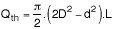
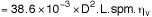
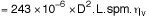
As shown under (Working principles), the theoretical output per stroke is given by:
Theoretical output per stroke for a single-acting triplex pump :

Theoretical output per stroke for a double-acting duplex pump: All in consistent units
Multiplying the theoretical output per stroke by the recorded strokes per minute and adjusting for the volumetric efficiency (ηv) will give the effective output, Qe.
Thus, the Theoretical output for a single-acting triplex pump Qe =
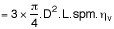
In Liters/Min
But in BBls/Min, the equation will be:
In the two equations where units are given, L, D, and d are expressed in inches, the unit normally used for this purpose. Similarly, the Theoretical output for a double-acting duplex pump Qe:
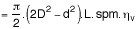
In Liters/Min
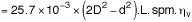
But in BBls/Min, the equation will be:
Pump Stroke Counters
Mud pumps are normally equipped with pump stroke counters. There are two types of stroke counters: one to indicate the pump rate (spm) and one to record the cumulative number of strokes. The latter type of counter monitors jobs such as chasing Casing Cementing Jobs, spotting slugs, and during well control.
Such counters are generally needed to follow the volumes pumped when volumetric control is essential. However, it is also necessary to know the pump efficiency to determine the delivered volume. Since this efficiency is pressure-related, it should always be checked when pumping with reasonable pressure.
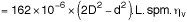
Volumetric Efficiency (ηv)
As stated in the previous paragraphs, volumetric efficiency is the relationship between a pump’s theoretical and effective output.
Loss of volumetric efficiency is mainly caused by the delay in valve shutdown. When the plunger motion reverses, the valves are not yet completely closed due to the mass inertia of the valves, and some of the liquid has the opportunity to flow back.
Major Causes Of Mud Pump Efficiency Drop
The following losses are recognized:
- Leakage losses of the discharge valve: As long as the discharge valve does not close completely during the suction stroke, a small amount of liquid will flow back from the discharge line into the cylinder.
- Leakage losses of the suction valve: As long as the suction valve does not close completely during the discharge stroke, a small amount of liquid will flow back from the cylinder into the suction line.
Other causes of loss in efficiency are:
- Losses due to a leaking stuffing box: During the suction stroke air is sucked in through the stuffing box. This air reduces the overall suction volume of the pump. During the discharge stroke, the liquid will leak through the stuffing box to reduce the quantity discharged.
- Leakage losses between piston and liner: The seal between the piston and liner may not be perfect. Consequently, some liquid may leak past the piston during the discharge stroke. It is also possible that some air is drawn in past the piston during the suction stroke of a single-acting pump.
- Leakage losses in suction lines: Leaks in the suction line may result in air being pulled into the drilling fluid flow during the suction stroke.
- Air or gas absorbed in liquids: The liquid may contain gas or air either dissolved or transported as small bubbles. One of the most common causes of suction aeration is mixing drilling fluid or adding chemicals through the hopper.
The highest practical efficiency should be maintained by regularly checking and servicing the pump.
Determination of The Pump Efficiency
The volumetric efficiency of a pump can be determined by pumping a known volume of þuid from one tank to another and comparing it with the theoretical volume calculated from the number of strokes made. This should be done while pumping over the well at a reasonable rate to ensure the pump delivers against pressure (a good time to do this is circulating before running casing and cementing).
The volumetric efficiency of a duplex pump will usually be 90 % or more. A triplex pump will usually have a volumetric efficiency greater than 95%.
Hydraulic Power Requirements
The hydraulic power (Ph) can be calculated using the equation below
Ph = ΔP x Qe
In Field Units:
Ph (HHP) = ΔP x Qe / 40
Ph is in psi, and Qe is in bbls/min
In practice, the input power supplied must be greater than the hydraulic horsepower because of
- The work required by the pump’s mechanism.
- The work absorbed by the hydraulic inefficiencies
The ratio of the hydraulic power Ph to the input power Pi is the mechanical efficiency ηm, Thus
Ph = Pi x ηm
- ηm is usually of the order of 0.85
Operating Limits
Operating limits are set in the first place by the fluid end dimensions but ultimately by the power end. The maximum discharge pressure is determined by the size of the liner installed and the available torque from the power end. The output volume for a given liner depends on the attainable pump speed, i.e., the available power from the power end.
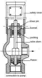
Mud Pump Relief Valves
Mud pumps must be equipped with pressure relief valves. These valves prevent too high a pressure from being built up in the circulating system. The relief valves most commonly used in Shell operations are the Cameron type “B” reset relief valve and the Cameron shear relief valve. A discharge line should be connected between this valve and the drilling fluid tank. For safety reasons, this relief valve discharge line must be tied down securely with its end facing down into the tank.
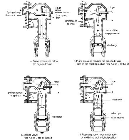
Cameron Shear Relief Valve
The Cameron shear relief valve pops open when the pressure setting is exceeded. The tripping pressure of the valve is determined by the strength of the shear pin. In this design, the valve snaps fully open, and there is no erosion of the piston or bore. A chart is printed on the manufacturer’s nameplate from which it is possible to see which size of the shear pin is needed for the required pressure limitation.
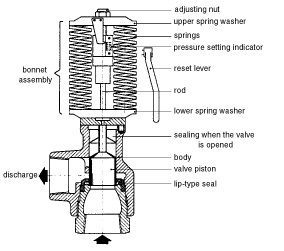
Cameron Type “B” Reset Relief Valve
The Cameron type “B” reset relief valve provides the following features:
- It opens fully when pressure is exceeded.
- The pressure setting is indicated by a pointer.
- The pressure setting can be changed with pressure on the valve by turning an adjusting nut.
- The valve design prevents leakage or erosion.
- All parts are enclosed.
- The valve is set by a reset lever.
- The valve can be opened at any time by pressing a release button.
The diagram below shows the valve’s operation.
Mud Pump Pulsation Dampeners
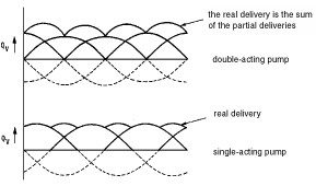
The speed of the piston is not constant during the suction and discharge strokes. During each stroke, the speed increases from zero to maximum at approximately the halfway position and then decreases to zero during the rest of the stroke (see Figure 20).
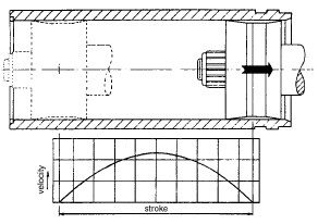
The change in piston speed and the fluid velocity causes the oscillating action shown in Figure 21. The effect is less severe for a single-acting pump than a double-acting one.
Suction Dampener
The pump draws this from the dampener during the suction stroke when it requires more liquid. Once the suction stroke has been completed, the air chamber absorbs the flow from the tank and dampens the shock in the suction line.
The Discharge Dampener
Contrary to the suction dampener, the discharge chamber, or pulsation dampener, is partly pressurized with nitrogen gas. During the discharge stroke, the gas in the pulsation dampener is compressed. At the end of the discharge stroke, the compressed gas expands, sustaining a reasonable steady flow in the discharge line and dampening the peaks in discharge pressure.
Figure 22 shows a commonly used pulsation dampener. It consists of a steel spherical body in which a diaphragm is fitted. The diaphragm separates the gas (nitrogen) from the drilling fluid.
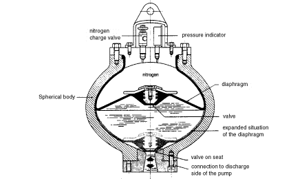
A charging valve and a pressure gauge are installed on top of the pulsation dampener cover to allow regular inspection and recharging. The pre-charge pressure should be 75 % of the minimum anticipated pump operating pressure to achieve a satisfactory dampening effect. The maximum pressure should not exceed 5250 kPa (750 psi).
WARNING: It is important that nitrogen only is used to charge the pulsation dampener. Serious accidents have been the result of using oxygen instead of nitrogen.
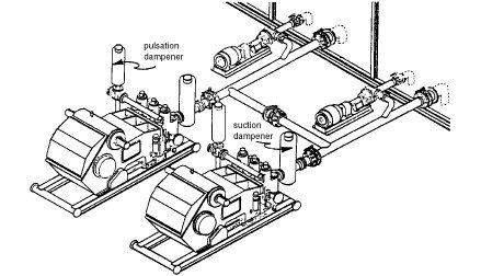
Dampener Location
The best dampening effect is achieved when the dampeners are installed close to the pump’s suction and discharge, as shown in Figure 23. The connection between the pump and the delivery line should include a hose to absorb vibration.
Booster/Charge Pumps
When the pumps run at the high end of their speed range, even the suction dampeners may be unable to cope with the peak intake rates. This results in cavitation with the cylinders not filling and shock loads in the pumps. To eliminate such problems, booster or charge pumps are hooked up to the mud pump suction lines to maintain positive pressure.
Attention must be paid to the following points to ensure that the pump cylinders are filled correctly to prevent piston hammering or pressure surges:
- The pump suction has to be as low as possible concerning the suction tank to maintain a positive fluid head.
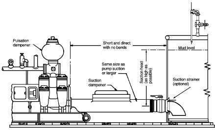
- To minimize suction resistance, The pump must be near the tank as possible. If friction losses are excessive, a booster pump in the suction line may be required (see Figure 3.3.24).
- The suction line must have an internal diameter as large as possible and be well sealed and secured to prevent air from being sucked into it.
- The tank has to be kept full to the normal operating level so that the maximum head is maintained on the suction.
Conclusion
Mud pumps are vital in oilfield rigs, circulating fluids such as water, oil, and drilling mud during exploration and drilling operations. They provide the pressure for the fluid to move through the drill string and into the formation.
For example, Gardner Denver offers various mud pumps to meet even the most severe drilling requirements. Their mud pumps are manufactured using only premium materials to ensure maximum performance and reliability under all drilling conditions.
Gardner Denver mud pumps feature an efficient design with robust components for long-term operation in harsh environments. They offer sizes ranging from small piston sizes to maximum piston rod loads.