Rock Roller cone Drill Bits as tricone receive predominant use throughout the world. As a result, an understanding of their design principles is essential for effective drilling operations. Common designs used by most manufacturers of tricone rock roller drilling bit will be discussed with a description of various special designs when applicable.
1st Design Feature: Roller TriCone Drill Bit Bodies.
The tricone drilling bit body consists of:
- the threaded connection,or shank, which attaches the tricone rock roller bits to the Drill String,
- the bearing pins on which cones are mounted,
- the lubricant reservoirs, which contain the lubricant supply for the bearings, and
- the watercourses through which the drilling fluid flows to clean the cuttings from the hole.
The individual body sections, including the integral bearing pins, are machined from forgings or castings of a nickel-chromium- molybdenum alloy steel of a carburizing grade. The bearing pin portion is selectively carburized (surface hardened) to provide a deep, wear-resistant case. The section is then oil-quenched hardened and tempered, resulting in wear-resistant bearing surfaces.
Each individual body component consists of a leg and bearing pin, as shown in Fig.1. (Tricone) Three Rock Roller Cone Drill Bits have three segments; four-cone bits have four bit segments. The individual segments are welded together to form the complete bit body.
Rock Roller Tricone Drill Bit Shank.
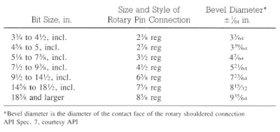
The shank of the Rock Roller Tricone Drill Bits connects the body to the bit sub or lowermost drill collar. The thread connections are API regular threads, a semi-rounded thread. Connection sizes for various diameter bits are shown in Table 1.
The top of the shank is used for identification. It contains such information as:
- bit diameter in inches,
- assembly number,
- type,
- manufacturer’s trademark, and
- serial number (see Fig.1).
The shank seat and shoulder provide the fluid seal between the tricone roller bit and the drill string. The threads will not form a pressure-tight seal and will result in a pipe washout problem if the Roller Cone Drill Bit is not made up properly. It is important, therefore, to ensure that the seat and shoulder are clean and not scarred prior to bit makeup.
The Roller TriCone Drill Bit Legs
The Rock Roller Cone Drill Bits legs, when welded together, provide the structural support for the bit. The dimple is a buildup of metal to provide additional support. Destruction of the bit body occurs when the legs or the weld fails. Bit destruction weights are generally assumed to be approximately 10,000 Ib/in. of bit diameter.
What Is The Roller Tricone Drill Bit Shirttail?
The lower exterior section of the bit leg is the” shirttail.” This area is an important part of the Roller Cone bit body because it is the only section that contacts the formation and therefore is subject to abrasive wear. The shirttail is often protected from wear by inserting tungsten carbide inserts or applying sintered tungsten carbide. Unusual wear in the shirttail area often indicates an undergauged hole that will give future problems when running a new, full-gauge bit.
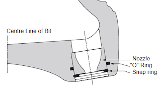
Tricone Drill Bit Nozzle Shrouds
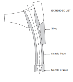
The tricone rock roller bits body is forged with nozzle shrouds for the jets in a jet-type bit. The shroud is located in the middle exterior segment of the body between each leg and directs the fluid flow at the bottom of the hole. Specially designed bits have extended shrouds that move the jet nearer the hole bottom, and a newly developed bit has one of the three shrouds directed up the annular space.
What are other Drill Bit Design Factors Related To Bit Body ?
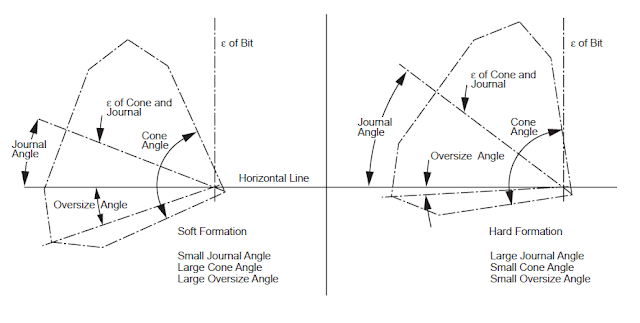
There are 2 important factors affecting the drill bit design which are journal angle and offset angle
2nd Design Feature : Roller Cone Drill Bit Watercourses
An important part of a Rock Roller Cone Drill Bits Design is the watercourses, without which the rest of the rock bits could not function as intended. Watercourses are passageways for the circulating fluid, which primarily brings cuttings to the surface and cleans the formation below the bit. The design of the passageway sand nozzles that direct the fluid at the bit differentiates between the two types of watercourses:
- conventional watercourses that direct the fluid onto the cutters and
- jet watercourses that direct the fluid onto the bottom of the hole.
Drilling fluid passes from the Drill String and out through nozzles in the bit. As it passes across the face of the bit it carries the drilled cutting from the cones and into the annulus. The original design for rock bits only allowed the drilling mud to be ejected from the middle of the bit. This was not very efficient and led to a build up of cuttings on the face of the bit (bit balling) and cone erosion.
A more efficient method of cleaning the face of the bit was therefore introduced. The fluid is now generally ejected through three jet nozzles around the outside of the bit body. The turbulence created by the jet streams is enough to clean the cutters and allow efficient drilling to continue.
What Is The Jet Nozzles Used In Drill Bit Watercourses?
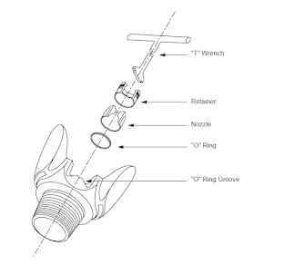
The jet nozzles are small rings of tungsten carbide and are available in many sizes. The outside diameter of the ring is standard so that the nozzle can fit into any tricone rock roller bits size. The size of the nozzle refers to the inner diameter of the ring.Nozzles are available in many sizes although diameters of less than 7/32″ are not recommended, since they are easily plugged. The nozzles are easily replaced and are fitted with an “O” ring seal . Extended nozzles may also be used to improve the cleaning action . The nozzles are made of tungsten carbide to prevent fluid erosion.
3rd Design Feature: Roller Cone Bit Bearing Lubrication System
Various types of Rock Roller Cone Drill Bits lubrication systems are used for bearing protection. Early systems included using the drilling fluid as the lubricant, while more recent systems use greases and oils for lubrication. Drilling fluids containing abrasive solids soon proved to be a limiting factor relative to long bit runs and, as a result, are seldom used as the lubricant in present-day bits. For Example the cones of a roller cone drill bit are mounted on jour-nals as shown in below design.
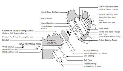
Roller Cone Drill Bit Bearing Design
There Are Three Common Types Of Bearings Design Used In These Roller Cone Drill Bits:
- Roller bearings System, which form the outer assembly and help to support the radial loading (or WOB)
- Ball bearings System, which resist longitudinal or thrust loads and also help to secure the cones on the journals
- A friction Bearing System, in the nose assembly which helps to support the radial loading. The friction bearing consists of a special bushing pressed into the nose of the cone. This combines with the pilot pin on the journal to produce a low coefficient of friction to resist seizure and wear.
All bearing materials must be made of toughened steel which has a high resistance to chipping and breaking under the severe loading they must support. As with all rock roller cone drill bits components, heat treatment is used to strengthen the steel.
The most important factor in the design of the bearing assembly is the space availability. Ideally the bearings should be large enough to support the applied loading, but this must be balanced against the strength of the journal and cone shell which will be a function of the journal diameter and cone shell thickness.
The final design is a compromise which ensures that, ideally, the bearings will not wear out before the cutting structure (i.e. all tricone roller rock drill bits components should wear out evenly). However, the cyclic loading imposed on the bearings will, in all cases, eventually initiate a failure. When this occurs the balance and alignment of the assembly is destroyed and the cones lock onto the journals.
Developments In Roller Cone Drill Bits Bearing Design :
Non-sealed roller ball bearings bit Design
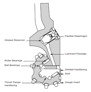
Non-sealed roller ball bearings do not have any mechanism to prevent drilling fluids entry into the bearing nor to prevent the exit of bearing lubricants. These bearings are generally packed with a highly viscous grease, as shown in Fig.10 . The grease lubricates the bearings and, since it has a high viscosity, is not easily displaced by the drilling fluid. If mud does enter the bearing area, however, galling and pitting soon begin, causing bearing failure.
Sealed roller ball bearings bit Design
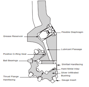
Sealed bearing bits were introduced in the late 1950s, to extend the bearing life of insert bits. The sealing mechanism prevents abrasive solids in the mud from entering and causing excess frictional resistance in the bearings. The bearings are lubricated by grease which is fed in from a reservoir as required. Some manufacturers claim a 25% increase in bearing life by using this arrangement .
Journal bearing bits Design
Journal bearing tricone roller bit do not have roller bearings. The cones are mounted directly onto the journal bearing. This offers the advantage of a larger contact area over which the load is transmitted from the cone to the journal bearing. The contact area is specially treated and inlaid with alloys to increase wear resistance. Only a small amount of lubrication is required as part of the sealing system. Ball bearings are still used to retain the cones.
4th Drill Bit Design Feature : Bit Sizes
Tricone roller drill bit is available in many sizes and types. Several of these characteristics are shown in Table.1. This type of information is useful in well-planning applications. Bit diameter tolerances must be compared with the drift diameter of the casing, to ensure that the bit can be run through the casing.
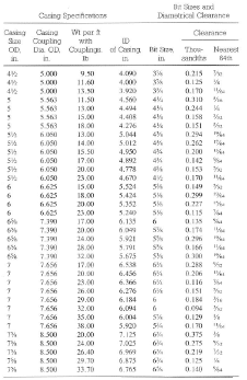
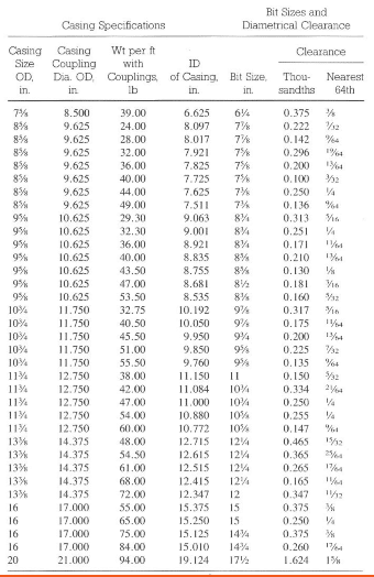
Sizing the bit program is dependent on the required casing sizes. Bits are available in almost any desired size range. However, nonstandard bits or unusual sizes may not possess all of the desirable features, such as center jet or gauge protection characteristics. In addition, bit selection and availability become more difficult in odd or small bit sizes (less than 6.5 in.). Table 5 illustrates size availability for Hughes insert tooth bits. Bit sizes less than 6 1/2 in. restrict bit type selection: In addition, bit selection is restricted for sizes greater than 12 1/4 in.
5th Drill Bit Design Feature : Roller Cone Drill Bit Cutting Structure
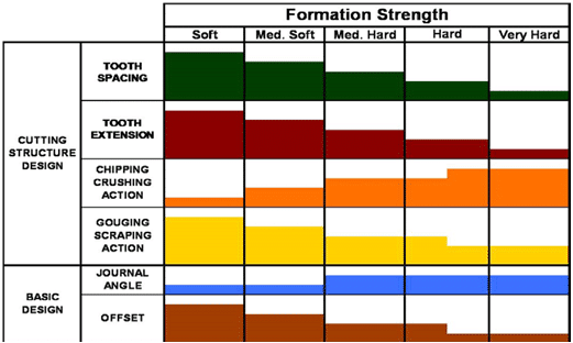
The selection of a Milled Tooth or Insert Rock Roller Tricone Drill Bits is largely based on the hardness of the formation to be drilled. The bit design of the cutting structure will therefore be based on the hardness of the formation for which it will be used.
What Is The Main Considerations In The Design Of The Milled Tooth Bit Cutting Structure?
2 main considerations in such design which are the height and spacing of teeth or inserts. According to theses consideration we can run the following classification.
Drill Bits Design For Soft Formation
Soft formation bits require deep penetration into the rock so the teeth are long, thin and widely spaced to prevent bit balling. Bit balling occurs when soft formations are drilled and the soft material accumulates on the surface of the bit preventing the teeth from penetrating the rock. The long teeth take up space, so the bearing size must be reduced. This is acceptable since the loading should not be excessive in soft formations.
Drill Bits Design For Moderately Hard Formation
Moderately hard formation bits are required to withstand heavier loads so tooth height is decreased, and tooth width increased. Such bits rely on scraping/gouging action with only limited penetration. The spacing of teeth must still be sufficient to allow good cleaning.
Drill Bits Design For Hard Formation
Hard formation bits rely on a chipping action and not on tooth penetration to drill, so the teeth are short and stubbier than those used for softer formations. The teeth must be strong enough to withstand the crushing/chipping action and sufficient numbers of teeth should be used to reduce the unit load. Spacing of teeth is less critical since ROP is reduced and the cuttings tend to be smaller.
What Is The Main Considerations In The Design Of The Insert Bit Cutting Structure?
The cutting structure for insert bits follows the same pattern as for milled tooth bits. Long chisel shaped inserts are required for soft formations, while short ovide shaped inserts are used in hard formation bits.
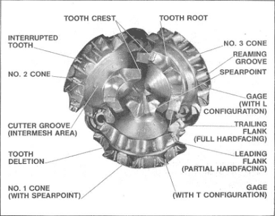
Positioning Roller Tricones Teeth
The positioning of the teeth on the cones of a roller cone bit is very important. The inner rows of teeth are positioned on the cones so that they intermesh. A relief ring is cut into the surface of one cone to provide space for the tooth rotation of an adjoining cone.
Hard Facing
Tungsten carbide hard facing is applied to the teeth of soft formation bits to increase resistance to the scraping and gouging action. Hard formation bits have little or no hard facing on the teeth, but hard facing is applied to the outer surface (gauge) of the bit.
If the outer edge of the cutting structure is not protected by tungsten carbide hardfacing two problems may occur.
- The outer surface of the bit will be eroded by the abrasive formation so that the hole diameter will decrease. This undergauge section of the hole will have to be reamed out by the next bit, thus wasting valuable drilling time
- If the gauge area is worn away it causes a redistribution of thrust forces throughout the bearing assembly, leading to possible bit failure and leaving junk (junk mill) in the hole (e.g. lost cones)
| FORMATION | TOOTH PROPERTIES | TOOTH ANGLE |
| SOFT formation cutting structure | Few in number, widely spaced, and placed in a few broad rows. Slender and small tooth angles. | 39° to 42° |
| MEDIUM formation cutting structure | Fairly numerous, with moderate spacing and depth. Teeth’s are strong, and are a compromise between hard and soft bits | 43° to 46° |
| HARD formation cutting structure | Many teeth’s are present. They are closely spaced and are short and blunt. There are many narrow rows with large tooth angles | 46° to 50° |
6th Drill Bit Design Feature : Roller TriCone Drill Bit Cones Geometry Design
As we said above the roller cones are mounted on bearings which run on pins that are an integral part of the bit body.
All three cones have the same shape except that the No. 1 cone has a spear point. One of the basic factors to be decided, in the design of the cones, is the journal or pin angle. The use of an Oversize Angle in drill bit design increases the diameter of the cone and is most suitable for soft formation bits. Although this increases cone size, the gauge tip must be brought inwards to ensure the bit drills a gauge hole.
At the end I suggest you visit these sources too to get full image about Roller Cone Drill Bit Design: