Well cement slurries are highly concentrated suspensions of solid particles in water. Their rheological Cement properties are related to those of the supporting liquid rheology, the solid volume fraction (volume of particles/volume of slurry), and interparticle interactions. The aqueous phase of a cement slurry contains ionic species and organic additives. Therefore, the rheological properties of the aqueous phase can differ greatly from those of water, notably when high-molecular-weight water-soluble polymers (e.g., Cement fluid-loss control agents) are added. The viscosity of the interstitial fluid can also vary significantly with temperature. In this article we handle cement slurry dispersants mechanisms & chemicals, we also think you might be interested in Cementing Chemical Additives article.
The solid volume fraction (SVF) can vary from about 0.2 for extended slurries to about 0.7 for reduced-water slurries. High SVF values generally result in high slurry viscosities, unless the controlled granulometry process is employed. Particle interactions depend primarily on the surface-charge distribution and steric hindrance effects caused by organic molecules adsorbed at the solid-particle surfaces.
Without modification, most cement slurries would not have the correct rheological properties for proper placement in long, narrow annuli. Cement slurry dispersants, also known in the construction industry as plasticizers and superplasticizers, are used to obtain the desired rheological properties.
This section discusses the various dispersant chemistries and the mechanisms by which they work. The most important factors affecting the response of cement slurries to dispersants are also discussed.
Chemical Composition of Cement Dispersants
Plasticizers
The first category of cement slurry dispersants, known as plasticizers in the concrete industry, includes lignosulfonates, modified lignosulfonates, and hydroxycarboxylic acids such as citric acid, tartaric acid, salicylic acid, gluconic acid, and glucoheptonic acid. Most plasticizers act as powerful cement retarders (Double, 1983), and in the well cementing industry they are considered more in this context than as dispersants (Messenger, 1978).
Lignosulfonates
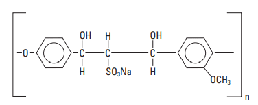
The lignosulfonates are most frequently used as dispersants in drilling mud formulations (Lummus and Azar, 1986) but are also effective in cement slurries (Every and Jacob, 1978; Detroit, 1980). However, they are also retarders and cannot be used at low temperatures. It is important to note that the performance of some lignosulfonates, notably those containing large quantities of sugars, is very sensitive to cement quality, and gelation problems are possible. This can be attributed to a dramatic acceleration of interstitial-phase (C3A and C4AF) hydration (Michaux and Nelson, 1992). A modified lignosulfonate, with a molecular weight in the range of 60,000 to 120,000, has been patented as a biodegradable dispersant for offshore applications (Chatterji et al., 2000). The chemical structure of a modified lignosulfonate is shown in Fig. 1.
Superplasticizers
A second category of cement slurry dispersants, known as superplasticizers in the concrete industry, includes polynaphthalene sulfonate, polymelamine sulfonate, and other sulfonated polymers such as polystyrene sulfonate and polycarboxylate-based products.
Polynaphthalene sulfonate (PNS)
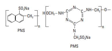
Polynaphthalene sulfonate (PNS) is by far the most common and cost-effective dispersant for well cements. However, it can no longer be used in some marine environments owing to its toxicity to algae, its tendency to bioaccumulate, and its nonbiodegradability in seawater. PNS is produced from naphthalene by sulfonation followed by polymerization with formaldehyde (Tucker, 1938). Residual sulfonic acid is neutralized with sodium hydroxide or lime. PNS is available in a wide variety of molecular weights and degrees of branching (Rixom, 1974; Costa et al., 1982). The repeating unit has the structure shown in Fig. 2. The value of n is typically low (about 10–20), but conditions are chosen to get a proportion of higher-molecular-weight product [molecular weight (MW) ≈ 100,000), because it is believed to be more effective. The commercial material is supplied as a powder or a 40% aqueous solution. For freshwater slurries, 0.2–1.0% active PNS BWOC is normally required for effective slurry dispersion; however, as shown in Fig. 3, concentrations as high as 4% BWOC may be necessary for slurries containing NaCl (Michaux and Oberste-Padtberg, 1986). PNS can be used at temperatures as high as 400°F [204°C]. As shown in Fig. 4, the PNS concentration required to decrease the yield value of a cement slurry below 10 lbf/100 ft2 [4.8 Pa] varies depending upon the cement source (Michaux et al., 1986).
![Influence of NaCl concentration on the dispersing
ability of PNS (15.8-lbm/gal [1,900 kg/m3 ] Class G slurry, 77°F [25°C]).](https://www.drillingmanual.com/wp-content/uploads/2021/04/image-137.png)
![Yield value versus PNS concentration for different API/ ISO Class G cements [77°F (25°C)]](https://www.drillingmanual.com/wp-content/uploads/2021/04/image-138.png)
Polymelamine Sulfonate (PMS)
Polymelamine sulfonate (PMS) is frequently used in the construction industry (Malhotra and Melanka, 1979) but to a limited extent in well cementing, probably because it is significantly more expensive than PNS. Melamine reacts with formaldehyde to form trimethylol melamine, which is in turn sulfonated with bisulfite and condensed to form a polymer. The structure of the base unit is shown in Fig. 2. The polymerization time influences the MW of the product. The most useful average MW is about 30,000. The product is available commercially in solid form or as a water solution (20% and 40%). As shown in Fig. 5, about 0.4% PMS (BWOC) is typically required to achieve proper dispersion; however, as observed with PNS (Fig. 4), this concentration varies from cement to cement. This product is effective at temperatures up to about 250°F [121°C].
![Figure 5. Yield value and plastic viscosity of Class G slurry containing PMS dispersant [120°F (49°C)].](https://www.drillingmanual.com/wp-content/uploads/2021/04/image-139.png)
Other sulfonated polymers
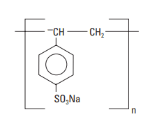
Other sulfonated polymers used as cement slurry dispersants include polystyrene sulfonate (PSS) and a condensation product of aldehyde and ketone that contains sulfonate groups. PSS is an effective cement dispersant, but it is rarely used because of cost (Biagini, 1982). Its chemical structure is shown in Fig. 6.
The MW of the aldehyde/ketone condensation is approximately 15,000, and the dispersant is reported to be salt tolerant (Aignesberger and Plank, 1989). It is commercially available as a powder or a 33% aqueous solution.
Polycarboxylate-based products
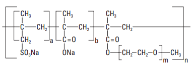
Polycarboxylate-based products were developed more recently than PNS and PMS. They are now extensively used in the construction industry and are beginning to be used for well cementing, notably at low temperatures (Volpert, 2002). The polymer structure is generally composed of a backbone chain with carboxylic groups upon which polyethyleneoxide (PEO) side chains are grafted. Sulfonate groups can also be present on the backbone chain (Fig. 7). These polymers are sometimes called “comb polymers.” They are manufactured from the monomers by a free-radical mechanism using peroxide initiators and, depending on the degree of prepolymerization, can be either block or random polymers.
Effect of Dispersants on The Rheology of Cement Slurries
The rheological behavior of well cement slurries can be studied using a rotational viscometer, which enables determination of the yield value and plastic viscosity. This is accomplished by plotting the shear stress against the shear rate. Figure 8 shows shear stress/shear rate plots for neat and dispersed cement slurries. The curves are approximately linear. The slope of the line is the plastic viscosity, and its ordinate at the origin is the yield value.
![Rotational viscometer readings for a neat and a dispersed 15.8-lbm/gal [1,900-kg/m3 ] Class G cement slurry at 120°F [49°C].](https://www.drillingmanual.com/wp-content/uploads/2021/04/image-143.png)
When the cement powder and water are mixed, a structure forms throughout the slurry owing to coagulation, which prevents flow below a given shear stress threshold, the yield value. At low shear stresses, below the yield value, the slurry behaves as a solid and does not flow. Above the yield value, it behaves as a liquid with a well-defined plastic viscosity. As shown in Fig. 9, cement slurry dispersants reduce both the yield value and plastic viscosity. At high concentrations, the yield value approaches zero and the cement slurry becomes essentially Newtonian. Unfortunately, very low yield values often lead to slurry instability, resulting in solids sedimentation or free water.
![Yield value, plastic viscosity, zeta potential, and free water for a cement slurry at 185°F [85°C]](https://www.drillingmanual.com/wp-content/uploads/2021/04/image-144.png)
When a solid with a characteristic net surface charge (such as a cement grain) is in contact with a solution, an electric double layer forms at the surface boundary. The inner layer, or Stern layer, which is approximately a single ion in thickness, consists of counterions that remain fixed to the solid surface. This is associated with a sharp fall in potential. The outer layer, or diffuse layer, extends some distance into the liquid phase. In this region, ionic species are free to move; however, because of the electrostatic field at the surface, there will be a preferential distribution of positive and negative ions. This results in a gradual decrease in potential towards the bulk solution, in which the charge distribution is uniform. The diffuse layer in highly ionic systems such as cement slurries is usually greatly compressed and typically only a few nanometers thick (Neubauer et al., 1998). The boundary between the Stern layer and the diffuse layer is called the shear plane. The electrical potential at the shear plane is known as the zeta potential or the electrokinetic potential. Dispersant molecules adsorbed at the surface of cement particles are positioned in the Stern layer and, therefore, contribute to the zeta potential. Figure 9 also shows how the zeta potential increases with PNS concentration. The zeta potential and cement dispersion are discussed later in this section.
Cement Slurry Dispersants – Mechanisms of action
The dispersive effect of superplasticizers is caused by the adsorption of superplasticizer molecules on the surfaces of cement grains throughout the initial hydration reactions to the final set. Depending on the chemical structure of the dispersant, the effect is attributed to electrostatic repulsions, steric repulsions between cement grains, or both.
In the absence of dispersant, Portland cements contain about 80 wt% of calcium silicates, C3S and C2S . During hydration, the surfaces of cement particles are mainly composed of silanol groups (–Si–OH). The silanol groups are hydrolyzed owing to the high pH (greater than 12.5) of the interstitial water.
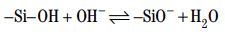
This should lead to electrostatic repulsion between the particles and to complete particle dispersion. However, the presence of calcium ions in the pore solution adds an attractive force. Calcium ions adsorb onto the negatively charged groups, conferring a global positive charge at the surface.
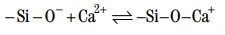
One calcium ion may bind two hydrolyzed silanol groups. As shown in Fig. 10, the silanol groups may be on the same grain or bridging two grains (Thomas and Double, 1981). It must be kept in mind that the positive charge on a cement particle in a neat slurry is a global or average charge. The surface of hydrating cement is likely composed of positive patches separated by neutral or even possibly negative regions (Michaux and Défossé, 1986). Therefore, the particles tend to align with positive or negative patches. The resulting attractive forces create a three-dimensional structure. The strength of this structure is measured macroscopically by the yield value.
To properly describe the interactions between the cement grains, one must also take ion-correlation forces into account. For monovalent ions such as sodium, the effective double layer repulsion is only slightly reduced. For divalent ions such as calcium, the ion-correlation attraction exceeds the repulsive forces between the charged surfaces (Israelachvili, 1992). The different effects of sodium and calcium ions on interparticle forces have been observed experimentally by atomic force microscopy (AFM). The predominant attractive force between the cement particles in the presence of calcium ions creates a structural network between the particles. This explains why a neat, nondispersed cement slurry has a yield stress (yield value) and does not behave as a Newtonian fluid. Cement particles are aggregated because of the coagulation process induced by calcium ions. These aggregates contain entrapped interstitial water, which is not available to lubricate the cement grains when the cement slurry is being pumped. Thus, large cement particle aggregates correspond to high slurry viscosity.
In the presence of dispersant, adding an anionic polyelectrolyte such as polynaphthalene sulfonate or polymelamine sulfonate can reduce the yield value and plastic viscosity of cement slurries. In theory, cationic polyelectrolytes could also be used for this purpose; however, they could react with anionic cement additives (e.g., retarders and fluid-loss additives) and cause performance difficulties. In addition, it is possible that the competition between the cationic polyelectrolyte and the calcium ions at the cement surface could impair the cement-hydration process.
Cement-slurry dispersion is achieved by adsorption of the dispersant molecules onto the cement-particle and hydration-product surfaces. The adsorption mechanism is still not clearly understood and may depend on the chemical structure of the dispersant. It is generally believed that the adsorption is caused by ionic bonds between calcium ions that are chemically adsorbed at the cement surface and the anionic groups (carboxylate or sulfonate) of the dispersant. The hydrophobic portion of the dispersant molecule may also preferentially adsorb onto cement-grain surfaces (Uchikawa et al., 1992).
A number of researchers have attempted to correlate dispersant adsorption with cement-slurry rheology and the zeta potential of cement particles. Michaux and Defossé (1986) performed such a study with Class G cement. To determine the amount of dispersant adsorbed onto hydrating cement particles, one measures the concentration of dispersant in the cement-pore solution and subtracts this value from the amount of dispersant originally added. Pore solutions are extracted from the cement slurry by filtration, and the dispersant concentration is determined by appropriate analytical techniques (e.g., ultraviolet spectroscopy for PNS and PMS). Figure 11 shows an adsorption isotherm for PNS in a cement slurry. The amount of adsorbed PNS varies with its concentration in the interstitial water, and the hydrating cement surfaces become saturated when a sufficient amount of PNS is present. When the cementparticle surfaces are saturated, any additional PNS remains in the pore solution. As hydration continues, the excess PNS can adsorb onto newly formed hydrationproduct surfaces. Adding extra dispersant can help reduce the loss of slurry fluidity that may occur as hydration progresses; however, overdosing can result in slurry sedimentation and free-water development.
![Adsorption isotherm and zeta potential for a diluted cement suspension [at 77°F (25°C)].](https://www.drillingmanual.com/wp-content/uploads/2021/04/image-150.png)
There is considerable controversy between researchers concerning the validity of zeta-potential measurements on cement systems. Questions generally arise about dilution factors, sample preparation, and measurement methods. Common methods to measure the zeta potential, such as electrophoresis or streaming potential, require a low particle concentration in the test fluid—much lower than that in a cement slurry. The zeta potential of cement particles depends on many parameters that can vary significantly with the water-tocement ratio. The most important parameters include the calcium concentration, alkali concentrations, pH, and nature and amount of hydration products. Hence, such methods have only a limited value for understanding the surface potential in a concentrated particle suspension like a cement slurry.
The only way to reliably measure the zeta potential in a concentrated particle suspension, with a solid-toliquid weight ratio as low as 0.3, is to use the electrokinetic sonic amplitude method. Charged particles exposed to an alternating electric field in a solution generate sound waves. The instrument detects the sound waves and determines the dynamic mobility of the particles, from which the zeta potential is calculated. Using this technique, Uchikawa et al. (1997) measured a surface potential of –1.8 mV for a nondispersed cement slurry and –11 mV for a slurry containing 0.6% BWOC PNS.
The time at which the zeta potential is determined is also an important parameter. Indeed, the electrical double layer around the cement particles is not in equilibrium (Nägele, 1985, 1986, 1987; Hodne and Saasen, 2000). This is owing to the continuous production of ions at the interfaces between unhydrated cement surfaces and hydration products. In addition, owing to the formation of new hydration products, the surface composition varies continuously with time.
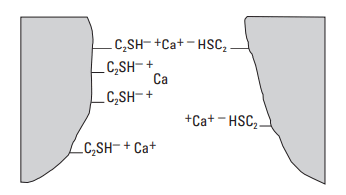
Figure 11 shows that the zeta potential increases when PNS is added to a cement slurry. This increase occurs because many of the anionic groups on the PNS molecules are not involved in the adsorption process. As a result, as schematically shown in Fig. 12, an adsorbed polyanionic molecule creates several negative charges. Clearly, when the cement-grain surfaces become saturated with dispersant molecules, no additional surface charge can be accommodated and the zeta potential levels off. The cement grains are negatively charged and repel each other because of repulsive electrostatic interactions.
Figure 9 shows that, at various PNS concentrations, there is a good correlation between the zeta potential, the rheological properties (yield value and plastic viscosity), and the free water. When the zeta potential reaches a maximum negative value, corresponding to the saturation of the hydrated cement surface by dispersant molecules, the yield value drops to zero. The plastic viscosity tends toward a minimum value owing to the deflocculation of cement aggregates. Thus, the effective volume of solids in the suspension is decreased, and the cement fluidity improves. With further addition of PNS, the free water increases dramatically because the cement particles are now free to sediment according to Stokes law. Such cement slurries are considered overdispersed.
When particles covered with a layer of adsorbed polymer approach one another, a repulsive force can be induced when the layers overlap (Fig. 13). It is likely that, for cement slurry dispersants with a bulky structure, this steric hindrance effect occurs in addition to electrostatic repulsion.
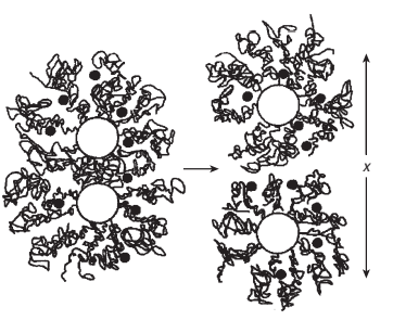
Polycarboxylate cement slurry dispersants are often comb polymers with grafted polyethylene oxide [(OCH2CH2)n, PEO] side chains. In the concrete industry, such polymers are among the most efficient superplasticizers. The polymer backbone consists of carboxylic groups and, sometimes, sulfonate groups. Adsorption of these polymers onto the hydrating cement grains probably occurs by way of the carboxylic groups. When the polymer is adsorbed onto a cement particle, a portion of the grafted side chains is oriented into the solution. In a good solvent such as water, solvent-chain interactions are energetically favored over chain-chain contacts. For the abovementioned comb polymers, the PEO side chains interact favorably with the aqueous medium and can stretch into the solution. As cement particles approach each other and the adsorbed layers of dispersant begin to overlap, a local increase in osmotic pressure occurs. The increased osmotic pressure induces a steric repulsive force between the cement particles, resulting in dispersion.
For polycarboxylate cement slurry dispersants, steric repulsion can be more important than electrostatic repulsion (Uchikawa et al., 1997; Yoshioka et al., 1997). Calculated interparticle potentials indicate that, because of the high concentration of electrolytes in cement pore solution (up to 1 M), the repulsive electrostatic forces generated by the polycarboxylates are never capable of overcoming the attractive Van der Waals forces (Flatt and Bowen, 2003). For this reason, the steric hindrance between the adsorbed layers of polymer must be the principal contributer to the dispersion mechanism.
Factors Affecting the Response of Cements to Dispersants
The concentration of dispersant required to effectively disperse a cement slurry varies considerably from cement to cement. This is clearly illustrated in Fig. 14, which shows the response of several cements that conform to the API/ISO Class G specification. The PNS concentration necessary to achieve full dispersion (yield value close to zero) varies from about 0.2% to 0.6% BWOC. Many cement properties can affect the performance of cement slurry dispersants:
- cement fineness
- nature and amount of calcium sulfates
- nature and amount of soluble alkali sulfates
- C3A content
- distribution of aluminate and silicate phases at the cement-grain surfaces (Vidick et al., 1987)
- reactivity of the cement phases (particularly C3A and C4AF) (Michaux and Nelson, 1992)
- cement aging (carbonation and prehydration of anhydrous cement).
In general, the amount of dispersant required to attain a given level of dispersion increases with the fineness of the cement. The number of adsorption sites on the cement particles increases exponentially as the particle size decreases.
The initial aluminate and silicate hydrates form around the cement grains during the preinduction period. The hydration of the interstitial phase (C3A and C4AF) during this period is the most important parameter affecting the slurry rheology. Several studies have shown that interstitial-phase hydration products adsorb much greater amounts of dispersant than silicate-phase hydration products (Uchikawa et al., 1992; Yoshioka et al., 2002). This effect is more pronounced with PNS and PMS than the polycarboxylate dispersants (Uchikawa et al., 1995). C3A is much more reactive than C4AF, especially at early hydration times. Thus, the amount of dispersant required to obtain a given level of dispersion increases with the C3A content.
Sulfate compounds in Portland cement control the interstitial-phase hydration. These include the alkali sulfates (Na2SO4, K2SO4, and NaKSO4) and the calcium sulfates [CaSO4 • 2H2O (gypsum), CaSO4 • 1/2H2O (plaster), CaSO4 (anhydrite), and CaK2(SO4)2 (syngenite)]. The alkali sulfates are very soluble and readily go into solution when the cement powder is added to water. The solubility and dissolution rates of the calcium sulfates are much lower (plaster > gypsum > anhydrite) and can be altered by the presence of organic compounds. The nature and the amount of sulfate compounds in Portland cement strongly affect the behavior and efficiency of cement dispersants.
- For all types of dispersants, the initial cement-slurry fluidity increases with the solubility of the calcium sulfates (Moulin and Broyer, 2003). However, the physico-chemical parameters governing longer-term cement-slurry fluidity are more complex.
- Cement-dispersant efficiency is low when anhydrite is the principal calcium-sulfate phase (Prince et al., 2003). The low dissolution rate of anhydrite inhibits ettringite formation; consequently, the interstitialphase hydration rate is high.
- PNS is more effective with cements that contain gypsum as the principal calcium-sulfate phase (Basile, 1987), rather than plaster or anhydrite.
- Sodium sulfate competes with PNS for adsorption sites during early hydration (Kim et al., 2000; Chandra and Björnström, 2002a and 2002b). This contributes to longer-term cement-slurry fluidity, because more PNS is left in the aqueous phase to adsorb onto future hydration products. Jiang et al. (1999) determined that, for most dispersants and cement compositions, the optimal dispersant concentration (expressed as %Na2O) is 0.4–0.5% BWOC.
The performance of dispersants can also be influenced by other physical and chemical factors.
- nature and concentration of salts present or added to the mix water
- mixing energy and mixing method
- mix-water temperature
- water-to-cement ratio
- when the dispersant is added [introduced in the mix water or added after cement is mixed with water (post-added)]
- chemical structure of the dispersant (e.g., MW, linear or branched polymer and steric size).
The slurry mixing conditions have a strong effect on the behavior of dispersed slurries. High mixing energy and long mixing times increase the amount of hydrates formed during the preinduction period. As a result, a greater amount of dispersant is consumed. The efficiency of dispersants is also inversely related to the mixwater temperature.
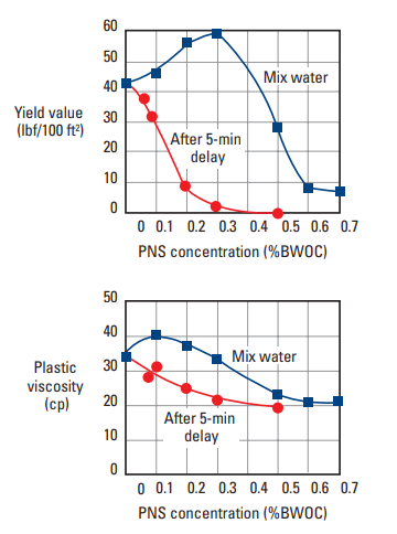
When the dispersant is present in the mix water during the preinduction period, a portion is consumed by the initial hydration products and is no longer available to perform its intended function. Numerous studies have demonstrated that cement slurry dispersants are more efficient when they are post-added to a cement slurry (Michaux et al., 1986; Michaux and Nelson, 1992; Collepardi et al., 1980; Chiocchio and Paolini, 1985). This effect is particularly strong with PMS and PNS (Uchikawa et al., 1995; Hanehara and Yamada, 1999). Delayed addition ensures that all of the dispersant is available to adsorb onto cement particles and hydration products. Experimental studies have shown that the optimal delay time is between 1 and 5 min after initial slurry mixing. As shown in Fig. 14, delaying the addition of PNS to a Class G cement slurry significantly improves the dispersant efficiency.
Particle Settling and Free Water
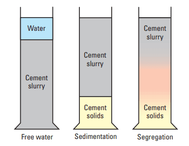
As a side effect of dispersant addition, the slurry may show sedimentation (a slurry-density gradient from the top to the bottom of a container resulting from particle settling), free water (a layer of nonparticle-laden fluid on top of the slurry), or both. Free water (also called free fluid) can occur with a homogeneous slurry below. Sedimentation can occur without forming a separate water layer.
- Free water: When the cement particles are not completely dispersed, they interact through electrostatic forces. A flocculated structure forms and supports the weight of a given particle. If the annulus in the well is sufficiently narrow, the weight of the particles is transmitted to the walls, and the slurry is self-supporting. Such cases are rare; normally, the weight of the cement particles is transmitted to the bottom by the gel lattice, and structural deformation occurs. Water is squeezed out of the lower portion of the slurry and is accommodated in the higher, less-stressed layers. The ability of the upper layers to accommodate the additional water is limited; thus, a layer of water may form at the top of the slurry (Fig. 15).
- Sedimentation: As described in the previous sections, cement slurry dispersants suppress the interactions between cement particles by neutralizing positively charged sites. When the process is complete, the particles repel each other through double-layer interactions. The range of action of these forces is a very short distance owing to the high ionic content of the aqueous phase. Therefore, the repulsive forces allow smooth particle packing. In a fully dispersed slurry, the particles are free to fall and collect at the container bottom. In reality, this ideal situation never occurs; instead, a density gradient forms. Three explanations may be proposed that incorporate the concept of particle polydispersity, that is, that small and large particles do not behave identically.
- Smaller particles have not settled yet.
- Brownian motion prevents small-particle settling.
- A flocculated gel exists but is not sufficiently strong to support the larger particles.
Prevention of free water and slurry sedimentation
Nonhomogeneous cement columns are not acceptable, particularly when the wellbore is highly deviated or horizontal. Sufficient set-cement strength and zonal isolation are jeopardized under such circumstances. Careful study of Fig. 9, a plot of free water and yield value versus PNS dispersant concentration, reveals a narrow range (0.2– 0.3 wt% BWOC) within which the slurry is sufficiently fluid and yet stable. In a field environment, it is difficult to control additive concentrations within such a narrow range. Therefore, antisettling agents are often added to broaden the concentration range within which low yield values and low free water can be obtained (Fig. 16). Antisettling agents are materials that restore some of the yield value but at a level compatible with the pumping conditions and friction pressure the exposed formation can bear. Examples of such materials are discussed below.
![Yield-value and free-water behavior of 15.8-lbm/gal [1,900-kg/m3] Class G cement slurries with and without antisettling agent at 185°F [85°C].](https://www.drillingmanual.com/wp-content/uploads/2021/04/image-156.png)
Bentonite may be used to reduce slurry settling (Morgan and DumSeawater and silicates can improve slurrbauld, 1954). Bentonite has the ability to absorb large quantities of water; as a result, slurry homogeneity is preserved.
Various hydrosoluble polymers reduce sedimentation by increasing the interstitial-water viscosity. The most commonly used materials are cellulosic derivatives such as hydroxyethylcellulose (HEC) and welan gum (Allen et al., 1991; Skaggs et al., 2001).
Seawater and silicates can improve slurry stability (Childs et al., 1984). In addition, metallic salts such as NiCl2 and MgCl2 build weak but extensive hydroxide structures throughout the slurry (Defossé, 1985a; Kar, 1986). As shown in Fig. 17, such structure building substantially reduces free water.
![Free water development of 15.8-lbm/gal [1,900 kg/m3] Class G slurries with two PNS dispersant concentrations [185°F (85°C)].](https://www.drillingmanual.com/wp-content/uploads/2021/04/image-158.png)
The efficiency of antisettling additives can be evaluated by measuring the density gradient in a column of set cement (Appendix B). A test slurry is placed in a cylinder and allowed to set. Wafers of the set cement are sliced from the top, middle, and bottom of the column. The weight difference between the wafers gives an indication of the extent of slurry sedimentation. Figure 18 illustrates typical results for two 15.8-lbm/gal [1.9 g/cm3 ] slurries.
![Comparison of density gradients in set-cement columns [15.8 lbm/gal [1,900 kg/m3 ]; 185°F (85°C)]](https://www.drillingmanual.com/wp-content/uploads/2021/04/image-160.png)
Ref: Schlumberger Well Cementing, Erik B. Nelson and Dominique Guillot