Cementing is the most important non-drilling function performed by the Drilling Foreman. Poor cementing properties & techniques used in oil and gas wells can cause countless drilling problems if the bottom joint of the surface pipe is lost. It can also cause costly remedial operations or loss of holes. A bad cement job can make an otherwise sound investment a disaster. Loss of control means loss of reserves and reduction in the potential of secondary recovery operations.
Oil & Gas Well Cement Functions
Cement has three functions.
- The cement slurry’s first and most important function is to carry all of the world’s trash (we call it additives) a mile or two under the ground and dispose of it.
- The cement must also be capable of supporting the casing.
- And finally, the cement must adequately isolate the intervals of interest.
All cementing design considerations should be directed at these functions. In addition to that, the Drilling Foreman should be concerned with accomplishing these functions as simply and economically as possible. We must become fundamentally familiar with the oil well-cementing properties to function in this capacity.
Gas & Oil Well Cementing Properties
Cements have various properties that are important to drilling personnel in the oil & gas rigs, such properties are as follows:
- Viscosity.
- Thickening time.
- Density.
- Yield.
- Fluid loss.
- Free water.
- Compressive strength.
Oil well cement Viscosity
Actually, the viscosity property of cement is normally 40-75 funnel seconds used in oil wells. Cement is a non-Newtonian fluid and is shear thinning. In other words, the cement gets thinner as the shear rate (velocity) increases. Accordingly, The Bingham Plastic and the Power Law Models can be used to describe the viscosity of cement at various shear rates; however, the Power Law Model is more accurate.
Viscosity is important when considering displacement mechanics. Low-viscosity cement will have better displacement properties at higher flow rates, while high-viscosity oil well cement may have better displacement properties at lower flow rates.
How to Control The Cement Viscosity
Viscosity is controlled by the amount of water added to the cement. Only 25% water by weight of cement is required for hydration, but more water is added to provide for permeability. Dispersants lower the yield point (check also Yield Point In Drilling Mud Formula) of cement slurries, reducing friction and allowing turbulence to occur at lower pump rates. Using dispersants allows the cement to be mixed with less water, yielding higher densities.
Cement Thickening Time Property
In general, cement’s thickening time can vary from 20 minutes to days depending upon pressure, temperature, additives, and how the cement is mixed. Published values for this oil well cement property are based on the API Standards for Temperature in Table 2. Thickening time tests should be run for actual well conditions when the conditions vary from the API standards.
| WELL DEPTH (feet) | BOTTOM-HOLE STATIC TEMPERATURE (°F) | BOTTOM-HOLE CIRCULATING TEMPERATURE (casing) | BOTTOM-HOLE CIRCULATING TEMPERATURE (squeeze) |
| 2,000 | 110 | 91 | 98 |
| 4,000 | 140 | 103 | 116 |
| 6,000 | 170 | 113 | 137 |
| 8,000 | 200 | 125 | 159 |
| 10,000 | 230 | 144 | 186 |
| 12,000 | 260 | 172 | 213 |
| 14,000 | 290 | 206 | 242 |
| 16,000 | 320 | 248 | 271 |
| 18,000 | 380 | 340 | — |
Thickening time tests are run in a pressurized consistometer, as shown in Figure 1. In fact, you should remember that a pressurized metal container does not always simulate downhole conditions. If some mixed water is lost to a permeable formation through filtration, the pumping time can be less than anticipated. Interruptions in pumping the cement can also cause a reduction in the thickening time. If the oil well cement can sit for a while, the thickening time property values are no longer applicable. The actual mixed water from the location should be used in the thickening time tests whenever possible.
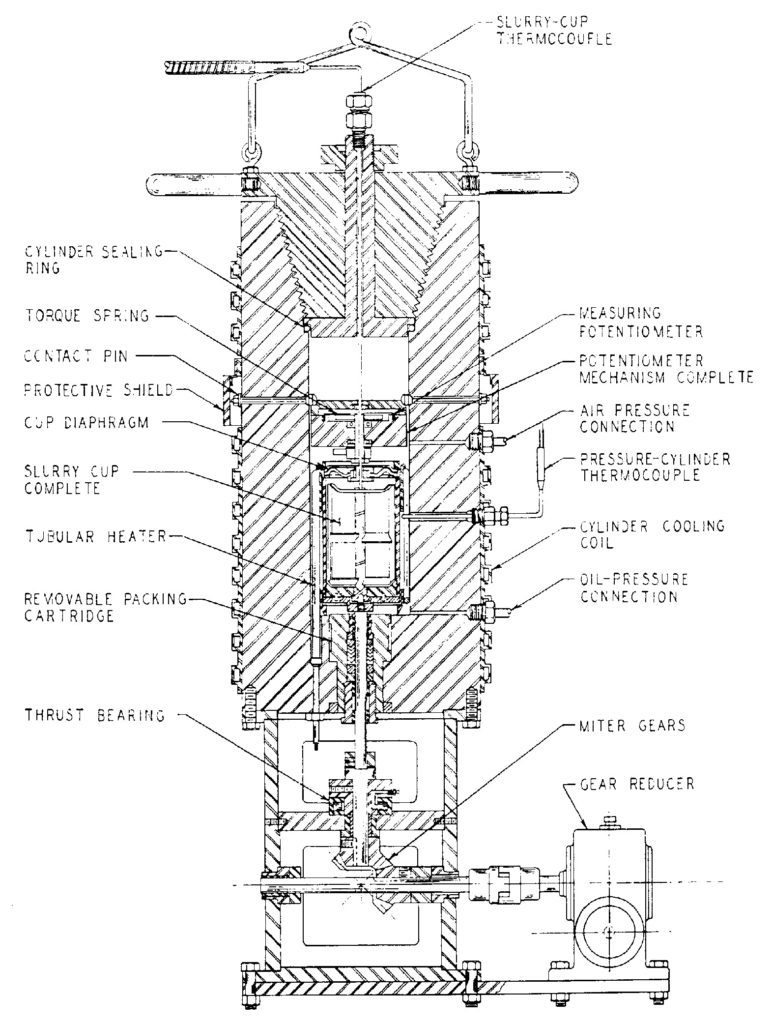
1
Cement Thickening Time Planning
Planned thickening times should allow ample time to place the cement, plus enough time should any unexpected problems occur. However, thickening times should not be excessive. Waiting on cement (WOC) to set before resuming drilling operations can be costly, especially in high-day rate operations. Excessive thickening time can also allow settling and separating slurry components, loss of hydrostatic head resulting in gas cutting, and formation of free water pockets.
Reducing Cement Thickening Time
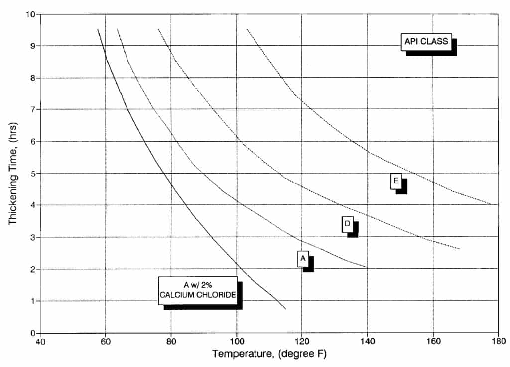
Cementers can easily reduce thickening times by adding accelerators such as calcium chloride. The temperature of the mix water is also important, particularly with accelerated cement. Figure 2 shows the effect of temperature on cement thickening time properties. The thickening time for Class A with two percent calcium chloride is ten hours at 60 degrees but reduces to 4 hours at 80 degrees. Increasing pressure will shorten the thickening time, although its effects are less pronounced than temperature.
Increasing Cement Thickening Time
By adding Retarders, we can increase thickening time, but at the same time, extenders reduce density. Adding more mix water will increase the thickening time with unretarded cement, but this may not be the case with retarded cement. The additional water can dilute the retarder concentration and, therefore, its effectiveness.
Cement Density
The density of cement can vary from less than 8.33 ppg for foamed cement to as much as 20 ppg for densified slurries. Cement density properties in oil & gas wells must be varied to prevent lost circulation or to control abnormal formation pressures.
Normal densities for API cement are shown in Table 3. As you can see, the density can be varied by altering the water content; however, care should be taken to avoid excess water. In general, too much water will increase the thickening time and reduce the strength of the cement.
We can always decrease the density by adding extenders such as pozzolans and bentonite, but you should remember that the extenders require more mix water. In addition to that, density can be increased by adding weight materials such as barite and hematite.
| API CLASS | WATER (gals/sk) | DENSITY (ppg) | YIELD (ft3/sk) |
| A | 5.2 | 15.6 | 1.18 |
| B | 5.2 | 15.6 | 1.18 |
| C | 6.3 | 14.8 | 1.32 |
| D | 4.3 | 16.4 | 1.06 |
| E | 4.3 | 16.4 | 1.06 |
| G | 5.0 | 15.8 | 1.15 |
| H | 4.3 | 16.4 | 1.06 |
Neat API Slurries from Halliburton Red Book – Oil well cement properties
Slurry Yield
The yield is the volume of cement mixture created per sack of initial cement. The yield can vary significantly depending on the additives. As an illustration, slurry yields can be as little as 0.90 ft3 per sack for densified cement to 4.70 ft3 per sack for a pozzolan, cement, and bentonite mix. Table 3 shows the yields for various API cements when the normal mix water is used.
Fluid Loss Of Cement
This oil well cement property (API fluid loss) test is conducted at 100 psi differential through a 325 mesh screen. The fluid loss for Class A neat cement will exceed 1,000 ml. The API well simulation test is run at various elevated temperatures and a pressure differential of 1,000 psi through a 325 mesh screen. The testing procedures can be found in API Spec 10. The temperature and differential pressure should be included whenever fluid loss tests are reported.
Usually, bentonite or high molecular weight polymers are added to the cement to reduce the fluid loss property. However, the fluid loss additives are temperature dependent and will lose some effectiveness at higher temperatures, like some polymers, which will even break down at high temperatures.
Reported optimum values for fluid loss vary considerably using the API well simulation test at the bottom hole circulating temperature. For a typical casing job, recommended fluid loss values range from a maximum of 100 ml to no control. The recommended API fluid loss ranges from 50 to 250 ml for liners and 50 to 200 ml for squeeze cementing. The literature also recommends keeping fluid loss below 150 ml when annular gas flow is problematic. For most applications, a fluid loss of 200 ml is adequate.
Free Water
Free water is caused by the separation of the mix water and cement solids. Surely, all neat cement will have some free water, which can contribute to annular gas flows. For example, In deviated and horizontal wells the separated mix water will migrate to the high side of the hole and cause a channel. In fact, the cement-free water content property in directional gas and oil wells or wells with annular gas flow problems shall equal zero. Recommended free water content for most vertical casing jobs is less than one percent. Adding fluid loss additives or 0.1% to 0.2% bentonite will reduce the free water content to near zero.
Cement Compressive Strength
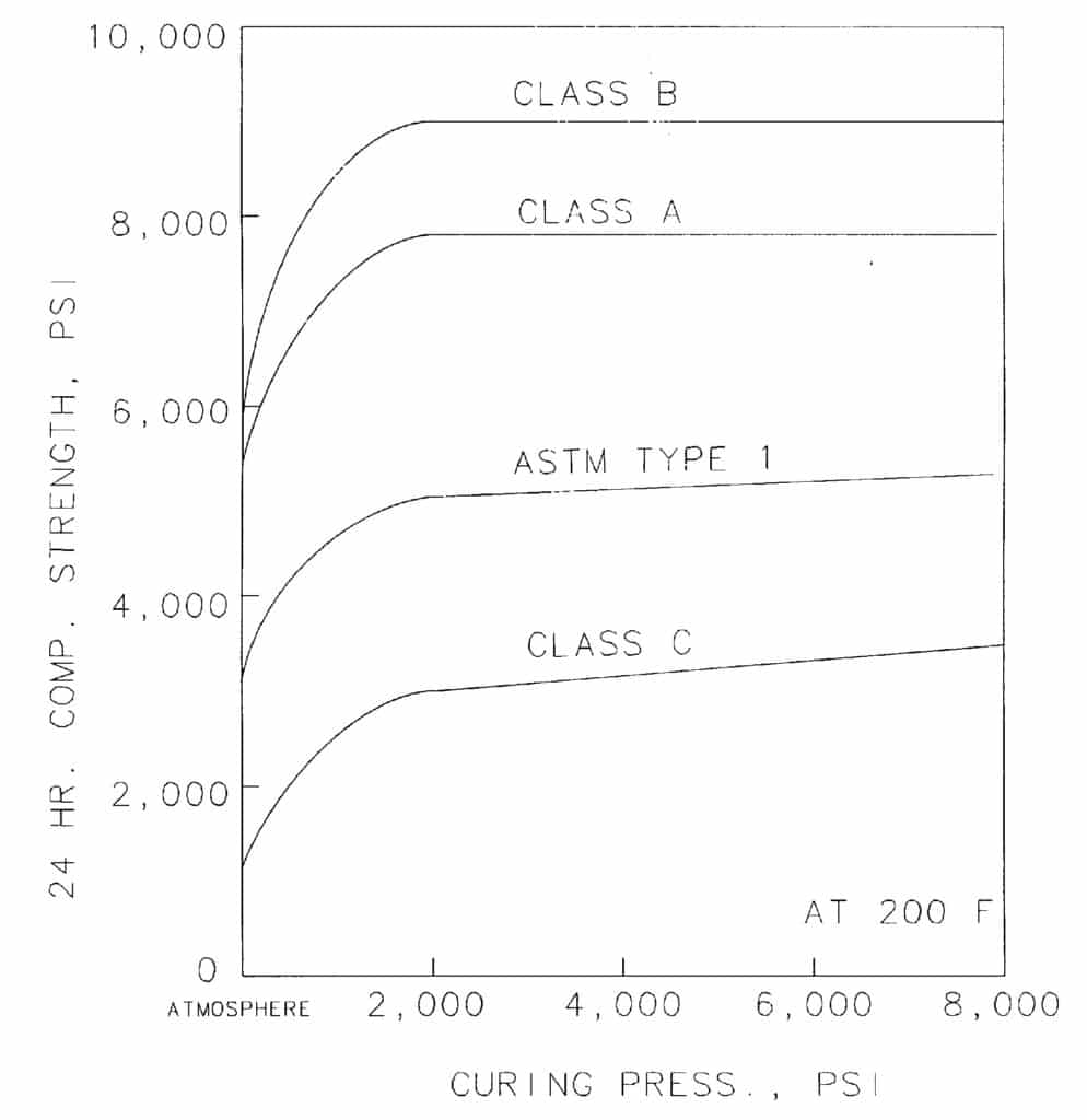
When cement sets, it develops a compressive strength over time,, which is a function of time, temperature, and pressure. As an illustration, Figure 3 shows the 24-hour compressive strength for various cement versus pressure at 200°F. Above 3,000 psi, there is very little change in compressive strength as the pressure increases. All API compressive strength tests are run at 3,000 psi when the depth is below 4,000 feet since there is little change in the expected compressive strength. Moreover, The API Spec 10 has pressure and temperature schedules for compressive strength tests based upon depth and anticipated temperature gradient.
Neat cement will attain the highest compressive strength. Usually, the compressive strength will be near the maximum within 72 hours. Extenders and using more mix water will decrease the ultimate compressive strength. At the same time, densifying a slurry by using the minimum mix water will increase the ultimate compressive strength. At the same temperature, accelerated cement will attain a higher compressive strength quicker than neat and retarded cement.
Common Cement Compressive Strength
A cement compressive strength property of 500 psi is sufficient for most oil field applications. Many filler cements have compressive strengths of 500 psi with relatively low densities and higher yields. Filler cement is less expensive than neat slurries. Thus, neat cement is placed across the producing formations and behind the shoe joint, and filler cement is used to fill the remainder of the annular capacity space that requires cement.
Cement Compressive Strength Tests
All compressive strength tests should be run by the service company before the actual cementing job. In critical situations, the actual cement composition and mix water should be used at simulated downhole conditions to determine compressive strength. In development areas, compressive strength can be spot-checked where the same cementing mixture is being used on similar wells. There is no need to run lab tests for each well. Dry cement samples should be collected in the field if a cementing problem occurs. Lab tests with the dry samples can be used to investigate the problem.
Effect Of Temperature on Cement Compressive Strength
Cement can suffer from strength retrogression at high temperatures in oil & gas wells, which is a loss in compressive strength property with time. It is also reported that above 230°F, there is a pronounced decrease in compressive strength and an increase in permeability of many commonly used cementing materials. Generally, additives that are not chemically reactive with the cement and require a high water-to-cement ratio produce cement of poor temperature stability. (Bentonite is probably the worst offender and should not be used in any composition above 4% by weight of the cement when temperatures are expected to exceed 230°F.)
Controlling Cement Compressive Strength
The addition of 35 to 40 percent silica flour will inhibit strength retrogression. Table 4 shows the increased strength of Class “B” and 50-50 Poz with 30 and 40 percent silica flour. Neat cement without silica flour would have compressive strengths of less than 1,000 psi, depending upon the bottom hole temperature. Also, Silica mix with Portland cement can be used at temperatures around 750°F. As with any critical cementing operation, the properties of the proposed cement mixture should be checked in the lab at downhole conditions in gas & oil wells. Strength retrogression should be added to the list of properties to check for very high temperatures.
| CEMENT | SILICA FLOUR (%) | CURED 7 DAYS (°F) 80 | CURED 7 DAYS (°F) 100 | HEATED 7 DAYS (°F) 400 | HEATED 7 DAYS (°F) 500 | HEATED 7 DAYS (°F) 600 |
| Class “B” | 30 | 1,400 | 1,985 | 6,600 | 4,450 | 2,600 |
| Class “B” | 40 | 1,215 | 1,810 | 6,550 | 6,300 | 5,920 |
| POZ | 30 | 560 | 1,225 | 4,200 | 4,850 | 6,000 |
| POZ | 40 | 775 | 1,240 | 3,400 | 4,200 | 5,850 |
Table 5 shows how the compressive strength will change with the addition of silica flour for class G cement. The samples were cured at 440°F for three and seven days and then cured at 725°F for 3 days.
Calcium aluminate cement
Calcium aluminate cement (usually termed cement fondue or limonite) can be used in applications where the temperature is expected to exceed 700°F, such as in-situ combustion wells where the temperature may reach 2,000°F. Calcium aluminate cement is manufactured from limestone and bauxite ore. Neat cement will have a density of 14.7 to 15.8 ppg and will attain a compressive strength of as much as 12,000 psi in 24 hours.
| SILICA FLOUR (%) | COMPRESSIVE STRENGTH (3 days) | COMPRESSIVE STRENGTH (7 days) |
| 0 | 545 | 425 |
| 40 | 11,025 | 10,010 |