A mud cooler removes heat from drilling fluid at the surface. Its usefulness depends on the thermal problem, the actual flow through the equipment and the conditions on the cooling side. A temperature reduction by itself does not establish whether a unit can handle the required drilling-fluid duty.
The Baker Hughes manual discusses heat exchangers as a response to excessive return-fluid temperatures. AVA describes another application: cooling drilling fluid when working through permafrost. These applications share a heat-removal mechanism, but their operating objectives differ. This guide explains that mechanism, develops a transparent heat-duty example and sets out the evidence needed for equipment selection. [1] [2]
What does a mud cooler do?
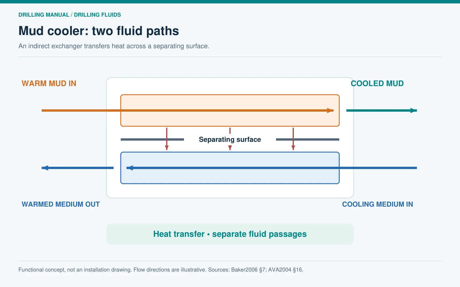
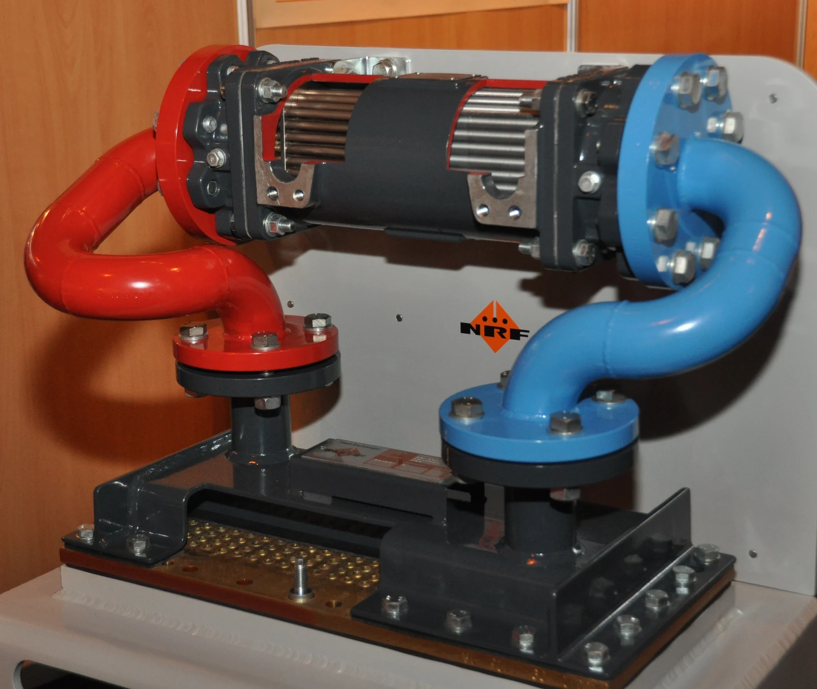
A mud cooler transfers heat out of a circulating drilling-fluid stream. In the indirect heat-exchanger arrangement illustrated here, drilling fluid and a separate cooling medium occupy different flow passages. Heat crosses the separating surface; intentional mixing of the two fluids is not part of this arrangement. AVA gives cold seawater as the heat-exchange medium in its Arctic example. That example establishes a useful principle without specifying a universal rig installation. [2]
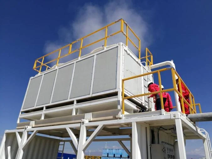
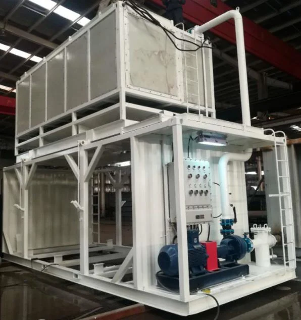
Follow the two paths separately. On the mud side, identify the source tank or return stream, the exchanger inlet, the exchanger outlet and the receiving compartment. On the cooling side, identify the supply, its inlet condition, the path through the exchanger and the destination of the warmed cooling medium. An equipment photograph alone cannot establish these connections.
The schematic is a functional illustration, not a piping and instrumentation diagram. Actual connections, valves, pressure ratings and operating sequences belong to the approved equipment documentation. For the wider circulation route, see the drilling circulation system.
Start with the temperature problem
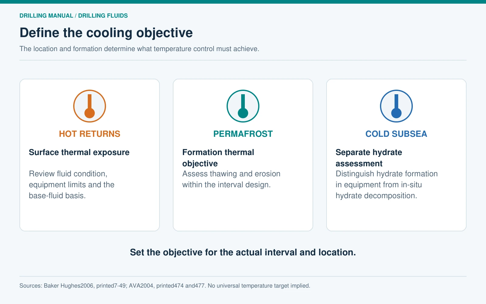
The first selection question is what the cooling system must achieve. “Cool the mud” is incomplete because it omits the protected location, the expected operating condition and the basis for an acceptable temperature.
For hot returns, Baker Hughes identifies effects on elastomers, fumes and the relationship between return temperature and the base oil’s flash point. It also cautions that surface-pit management alone may provide only limited cooling. These are reasons to evaluate a dedicated thermal-control measure; the manual does not supply one outlet-temperature target for all wells. [1]
For permafrost, AVA discusses the effect of fluid temperature on thawing and erosion. It also distinguishes the decomposition of hydrates in a formation from hydrate formation in cold subsea equipment. A cooling strategy for one situation cannot simply be transferred to the other. The fluid program must define the objective for the actual interval. [2]
Separate surface temperature from downhole conditions
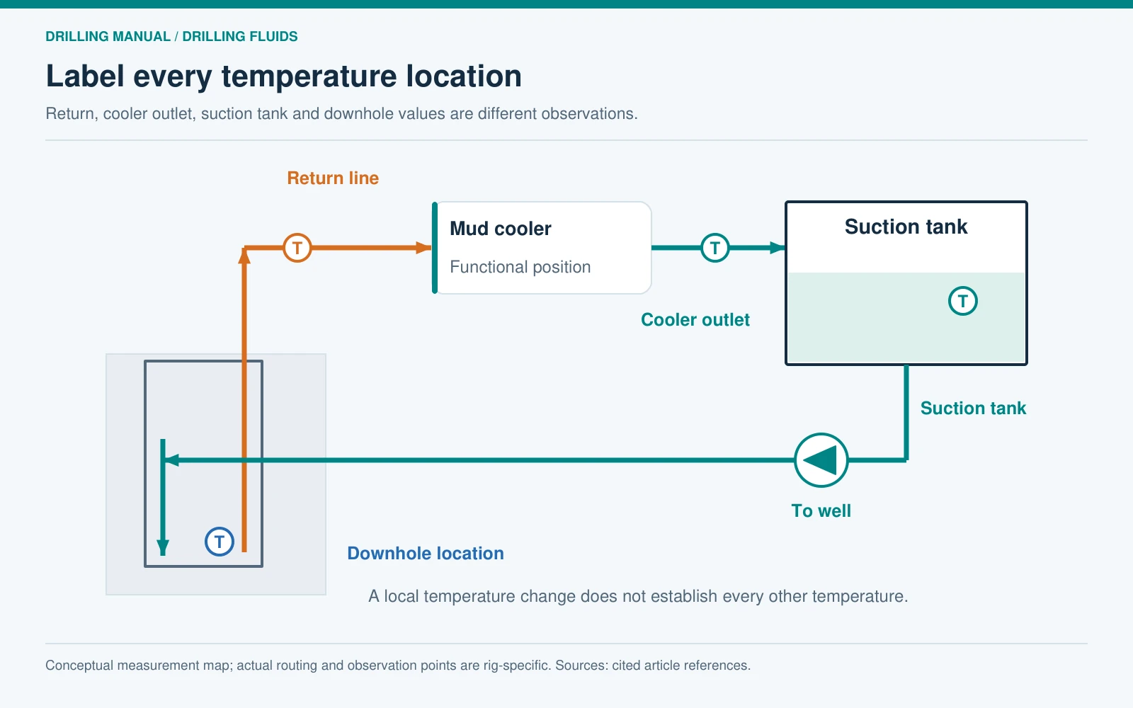
Return-line temperature, mud cooler outlet temperature, suction-tank temperature and bottomhole temperature describe different locations. Use the location name beside every reading. A lower cooler outlet reading demonstrates a local change; it does not independently establish the temperature at a downhole tool or throughout the annulus.
Temperature also interacts with wellbore mechanics. Aird explains that cooling can change near-wellbore hoop stress and that the effect depends on the existing stress and pressure conditions. This is a reason to review the planned thermal change within the well design, not to pursue the lowest achievable surface temperature as an objective in itself. [3]
The measurements behind mud cooler duty
A useful mud cooler assessment starts with simultaneous operating data. Record mud flow through the exchanger, mud inlet and outlet temperatures, fluid density and the basis for its heat capacity. Record cooling-medium inlet and outlet temperatures and its flow as well. Keep the time, operating state and measurement location with each value.
The distinction between total rig circulation and exchanger flow matters. If some flow follows another route, the rig’s total circulation rate cannot be substituted for the measured flow through the cooler in a heat-removal calculation. Similarly, a tank reading taken after mixing does not automatically represent the exchanger outlet.
| Input | What to record | Why it matters |
|---|---|---|
| Mud-side flow | Flow through the exchanger, unit and measurement basis | Determines the mass passing through the thermal boundary |
| Temperatures | Inlet, outlet, location and common time period | Defines the measured temperature change |
| Density | Value, temperature and fluid identity | Converts volume flow into mass flow |
| Heat capacity | Value, units, source and applicable conditions | Relates temperature change to heat per unit mass |
| Cooling medium | Identity, inlet condition, outlet condition and flow | Describes the other side of the heat-removal process |
| Operating context | Fluid condition, line-up and changes during the observation | Supports a meaningful comparison between runs |
The manuals define specific heat in terms of the energy required to change the temperature of a unit mass. The following calculation applies that definition to a flowing stream. It is an original teaching calculation, rather than a cooler rating taken from a manufacturer. [1]
Worked heat-duty example
For steady flow with an approximately constant heat capacity and no phase change, the sensible heat removed is:
Heat-removal rate = volume-flow rate × density × specific heat capacity × temperature drop.
Use a consistent unit set: m³/s × kg/m³ × kJ/(kg·K) × K gives kJ/s, which is kW. A temperature difference has the same numerical value in kelvin and degrees Celsius.
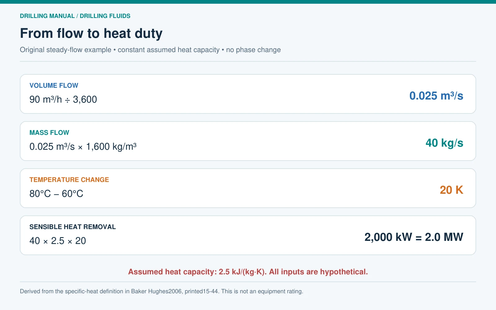
Assume a mud cooler handles 90 m³/h of mud with density 1,600 kg/m³. For this example only, assume a heat capacity of 2.5 kJ/(kg·K) over the temperature interval. The measured inlet and outlet temperatures are 80°C and 60°C.
- Convert flow: 90 ÷ 3,600 = 0.025 m³/s.
- Calculate mass flow: 0.025 × 1,600 = 40 kg/s.
- Calculate temperature drop: 80 − 60 = 20 K.
- Calculate heat removal: 40 × 2.5 × 20 = 2,000 kW, or 2.0 MW.
Every value above is hypothetical. In particular, 2.5 kJ/(kg·K) is an assumed input, not a standard heat capacity for drilling mud. This calculation describes the required or observed sensible duty under its assumptions. It does not establish exchanger area, allowable pressure drop, cooling-medium demand or the capacity of an available package.
Why temperature drop is not enough
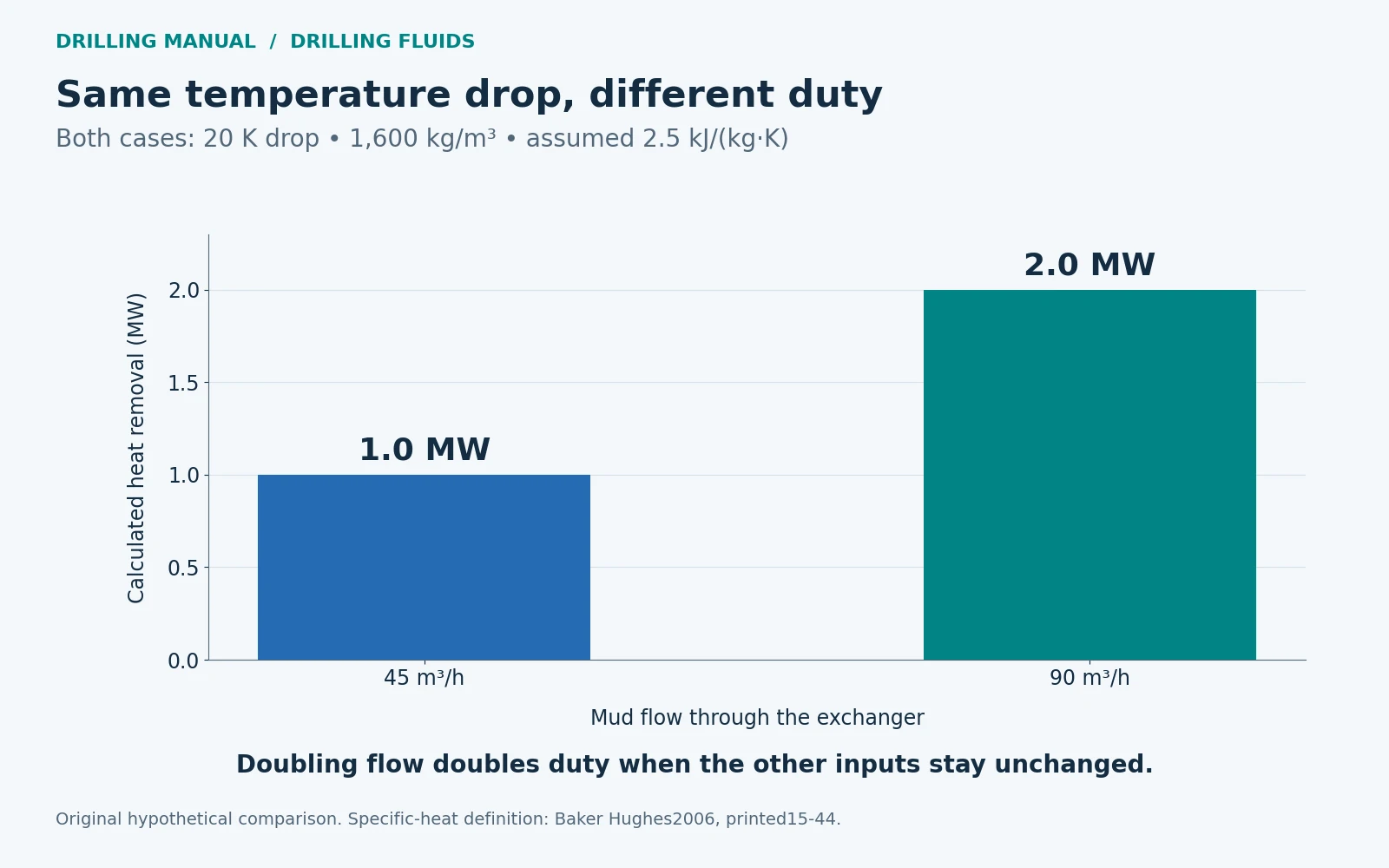
Keep the mud cooler example’s density, heat capacity and 20°C temperature reduction unchanged, but halve the exchanger flow to 45 m³/h. The calculated heat removal becomes 1.0 MW. Both observations show the same temperature drop, yet the second removes half as much heat per unit time.
This is why a report stating only that a mud cooler reduced temperature by a certain number of degrees is incomplete. To compare two observations, establish the flow, fluid properties and cooling-side conditions for each. A difference in any of those inputs changes what the reported temperature reduction means.
Fluid condition is part of equipment selection
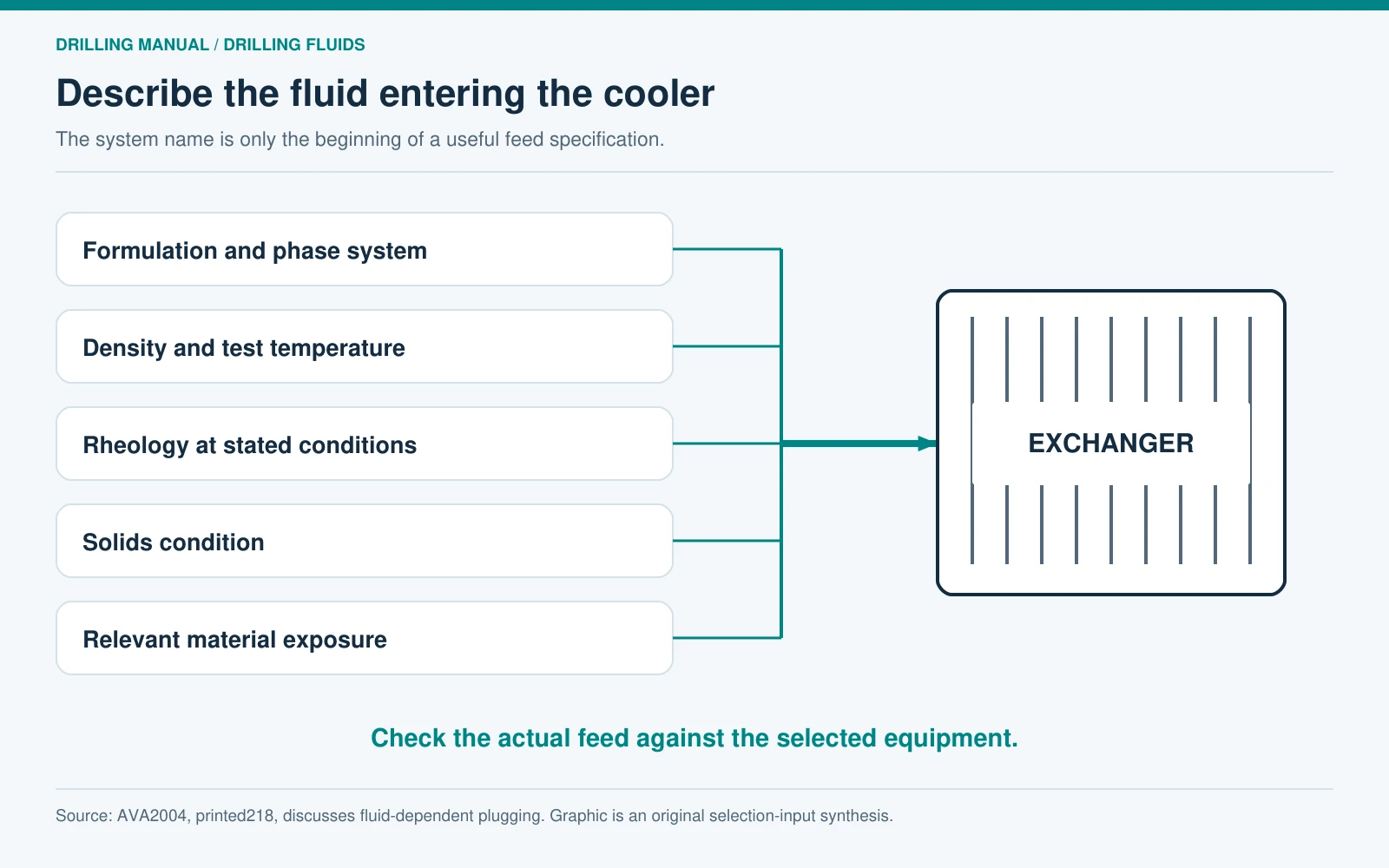
Describing the mud cooler feed as “water-based mud” or “oil-based mud” is not a complete equipment specification. Include the actual formulation, density, solids condition, relevant rheology and any material expected to pass through the chosen route. AVA’s Arctic discussion notes different plugging tendencies for its guar and xanthan systems. That historical example supports checking the actual fluid against the equipment passages; it does not prove that one polymer is universally suitable for every cooler. [2]
Record the fluid condition expected during the demanding part of the interval, not only the condition of a clean commissioning sample. The supplier needs that information to evaluate the proposed passages, materials and operating arrangement. Any strainers or other protective equipment must be assessed as part of the actual circulation route; their presence should not be assumed from a generic sketch.
For the pump supplying that route, the required flow and system resistance must also be established. The main rig mud-pump guide provides broader pump context; a cooler circulation duty needs its own equipment assessment.

Cooling and fluid conditioning answer different questions
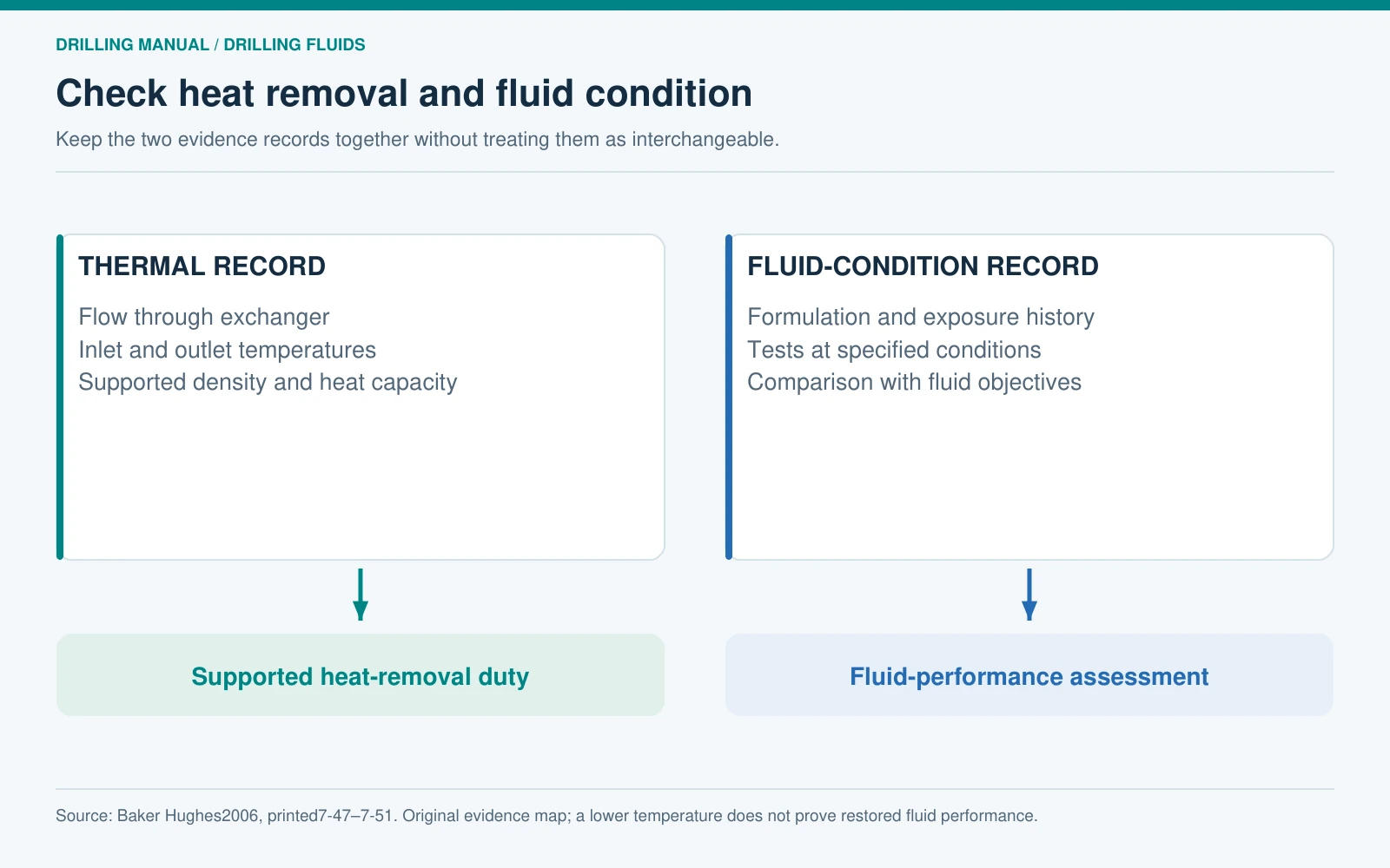
Baker Hughes describes temperature effects on density, rheology, filtration and chemical condition. It also explains mechanisms of polymer deterioration and notes the importance of examining bottoms-up samples after a long exposure at downhole temperature. A mud cooler outlet reading and a fluid-performance test therefore provide different evidence. [1]
Lowering a sample’s temperature can change its measured properties without demonstrating that its original chemical performance has returned. Conversely, a viscosity change alone does not establish a cooling-system fault. Compare fluid tests at their specified test conditions and interpret them with the formulation and exposure history.
Keep the thermal-performance record beside the fluid-condition record. The first asks how much heat is being removed under stated conditions. The second asks whether the drilling fluid still performs the required functions. A successful cooling observation does not replace the second assessment.
Build a mud cooler selection brief
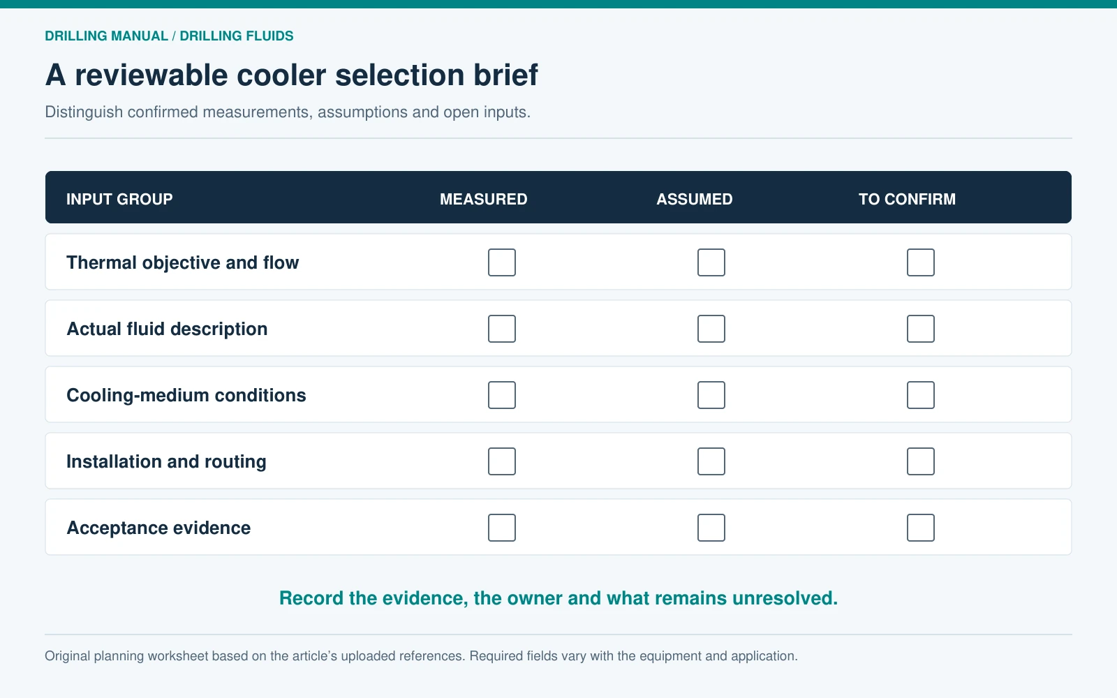
Turn the mud cooler inputs into a short, reviewable equipment brief. State the thermal objective, the location where it applies, the required flow envelope and the fluid properties used in the duty calculation. Then document the cooling-medium conditions available at the site and the installation constraints that the supplier must evaluate.
Keep measured values, assumptions and unresolved inputs separate. For example, a measured mud inlet temperature and an assumed heat capacity should not be presented with equal certainty. Identify the person responsible for confirming each open input and the consequence for equipment selection if it changes.
- Thermal basis: source of inlet conditions, proposed outlet requirement, flow range and heat-capacity basis.
- Fluid basis: system identity, density, test conditions, solids and relevant material exposure.
- Cooling-side basis: medium, supply conditions, available flow and approved destination.
- Integration basis: source and receiving compartments, routing, pressure constraints, utilities, access and equipment documentation.
- Verification basis: measurement locations, instruments, acceptance conditions and the authority agreeing the result.
Download the mud cooler duty-input worksheet to record these items. The worksheet is an information-gathering aid; the final thermal and mechanical rating comes from the engineering assessment for the selected equipment.
Evaluate performance against the agreed conditions
Use the same mud cooler measurement boundary during the equipment evaluation and subsequent comparisons. Check that the observed run represents the stated feed, flow and cooling conditions. Record a change in line-up or fluid composition when it occurs, so that a later change in temperature is not attributed to the exchanger without supporting evidence.
An acceptance record should bring together the inlet/outlet observations, the supported duty calculation, the supplier’s applicable limits and the fluid-condition checks. If an input is missing, identify the unresolved conclusion explicitly. For instance, inlet and outlet temperatures without flow can establish a temperature difference but cannot establish the heat-removal rate.
This approach keeps the mud cooler tied to a defined job. It also gives the rig and fluids teams a practical record to revisit when the interval, fluid formulation or operating conditions change.
Mud cooler questions
Is the cooler outlet temperature the same as suction temperature?
Not necessarily. The readings refer to different locations, and the fluid may mix with other streams before reaching the suction compartment. Record both locations and the actual routing.
Does a larger temperature drop always mean more cooling?
No. Heat-removal rate also depends on mass flow and heat capacity. Compare complete operating records, as illustrated by the 1.0 MW and 2.0 MW examples.
Can the same duty calculation be used for different mud systems?
The sensible-heat relationship can be applied under its stated assumptions, but each system needs its own supported density and heat-capacity inputs. Do not transfer the example’s assumed values to a field fluid.
Does cooling reverse thermal degradation?
A lower temperature alone does not demonstrate restored fluid performance. Assess the formulation, exposure history and tests at their specified conditions; Baker Hughes distinguishes temperature-dependent behavior from deterioration of fluid components. [1]
Can a mud cooler be selected from flow rate alone?
Flow is only one input. The temperature objective, fluid properties, cooling-medium conditions and equipment constraints must be specified before the package can be evaluated.
References
- Baker Hughes Drilling Fluids. Drilling Fluids Reference Manual. Revision 2006. Borehole Problems: temperature limitations, fluid properties, hot returns and planning; Glossary: specific heat. Printed pages: 7-47–7-51 and 15-44. PDF pages in the edition consulted: 448–452 and769.
- AVA S.p.A. Drilling Fluids Manual. Version 1, November 2004. Arctic spud fluids; gas hydrates; permafrost. Printed pages: 218,473–474 and 477. PDF pages in the edition consulted: 220,475–476 and 479.
- Peter Aird. Deepwater Drilling: Well Planning, Design, Engineering, Operations, and Technology Application. Gulf Professional Publishing, 2019. Chapter 2, High Bottom-Hole Temperature Wells. Printed pages: 59. PDF pages in the edition consulted: 64.