Most formation solids can be removed by mechanical means at the surface as shale shaker screens. Small particles are more difficult to remove and have a greater effect on drilling fluid properties than large particles. The particle size of drilled solids incorporated into drilling fluid can range from 1 to 250 microns (1 micron equals 1/25,400 of an inch or 1/1,000 of a millimeter). Table 1 lists the approximate sizes of contaminating solids that can be removed.
| Material | Diameter, microns | Screen mesh required to remove | Diameter, inches |
| Clay Colloidal Bentonite | 1 | — | 0.00004 |
| 5 | — | 0.0002 | |
| Silt Barites Fine cement dust | 44 -6 | 1,470-400 | 0.0004 -0.0015 |
| Fine sand | 44 | 325 | 0.0015 |
| 53 | 270 | 0.002 | |
| 74 | 200 | 0.003 | |
| API sand | 105 | 140 | 0.004 |
| 149 | 100 | 0.006 | |
| Coarse sand | 500 | 35 | 0.020 |
| 1,000 | 18 | 0.040 |
Shale Shaker Screens Effectiveness & Design
Two factors that determine the effectiveness of a screen are mesh size and screen design.
Mesh size
The screen opening size determines the particle size a shaker can remove. Screen mesh is the number of openings per linear inch as measured from the center of the wire. For example, a 70 by 30 oblong mesh screen (rectangular opening) has 70 openings along a one-inch line one way and 30 openings along a one-inch line perpendicular to the first.
Actual separation sizes are determined by factors such as particle shape, fluid viscosity, feed rates, and particle cohesiveness. Some muds can form a high surface-tension film on the wires of the screen and reduce the effective opening size of the screen. Tables 2 and 3 list specifications for different screen sizes and mesh shapes.
| Mesh | Wire diameter Inches | Opening width Inches | Opening width Microns | Percent |
| 20 × 20 | 0.016 | 0.0340 | 863 | 46.2 |
| 30 × 30 | 0.013 | 0.0203 | 515 | 37.1 |
| 40 × 40 | 0.010 | 0.0150 | 381 | 36.0 |
| 50 × 50 | 0.009 | 0.0110 | 279 | 30.3 |
| 60 × 60 | 0.0075 | 0.0092 | 234 | 30.5 |
| 80 × 80 | 0.0055 | 0.0070 | 178 | 31.4 |
| 100 × 100 | 0.0045 | 0.0055 | 140 | 30.3 |
| 120 × 120 | 0.0037 | 0.0046 | 117 | 30.5 |
| 150 × 150 | 0.0026 | 0.0041 | 104 | 37.4 |
| 170 × 170 | 0.0024 | 0.0035 | 89 | 35.1 |
| 200 × 200 | 0.0021 | 0.0029 | 74 | 33.6 |
| 250 × 250 | 0.0016 | 0.0024 | 61 | 36 |
| Mesh | Wire diameter Inches | Opening width/length Inches | Opening width/length Microns | Percent open area |
| 20 × 30 | 0.014 | 0.036/0.0193 | 914/490 | 41.8 |
| 20 × 40 | 0.013 | 0.037/0.012 | 940/305 | 35.6 |
| 20 × 60 | 0.009 | 0.041/0.0076 | 1,041/193 | 34.0 |
| 40 × 60 | 0.009 | 0.016/0.0076 | 406/193 | 29.4 |
| 40 × 80 | 0.0075 | 0.0181/0.0055 | 457/140 | 35.6 |
The size of the openings in the screen is obviously related to the size of the solids that will pass. However, over the years this led to misunderstandings as creative screen manufacturers developed layered screens and/or shale shaker screens with oblong openings. This made it difficult to decide what the maximum size of particles would be that could pass such a screen. Manufacturers would only give a so-called 50% cut size or median size. Spherical particles would be used to determine this 50% cut size.
In the end, the information given did not represent what the client was looking for. Under the API 13C scheme, a manufacturer is obliged to test the screens using aluminum oxide particles that resemble the general shape of cuttings. The particle size that is quoted for the screen must be the maximum size of any particle that would pass the screen. A set of API indicators was developed that is still related to the approximate throughput sizes of the previously used Mesh system. Both the API indicator and the maximum size of a particle passing the screen must be mentioned on the screen label.
| D100 Separation (Microns) | API Screen Number |
| >780,0 to 925,0 | API 20 |
| >655,0 to 780,0 | API 25 |
| >550,0 to 655,0 | API 30 |
| >462,5 to 550,0 | API 35 |
| >390,0 to 462,5 | API 40 |
| >327,5 to 390,0 | API 45 |
| >275,0 to 327,5 | API 50 |
| >231,0 to 275,0 | API 60 |
| >196,0 to 231,0 | API 70 |
| >165,0 to 196,0 | API 80 |
| >137,5 to 165,0 | API 100 |
| >116,5 to 137,5 | API 120 |
| >98,0 to 116,5 | API 140 |
| >82,5 to 98,0 | API 170 |
| >69,0 to 82,5 | API 200 |
| >58,0 to 69,0 | API 230 |
| >49,0 to 58,0 | API 270 |
| >41,5 to 49,0 | API 325 |
| >35,0 to 41,5 | API 400 |
| >28,5 to 35,0 | API 450 |
| >22,5 to 28,5 | API 500 |
| >18,5 to 22,5 | API 635 |
Screen design
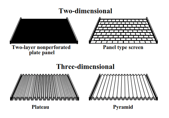
Screens are available in two- and three-dimensional designs.
Two-dimensional screens can be classified as:
- Panel screens, with two or three layers bound at each side by a one-piece, double-folded hook strip
- Perforated plate screens, with two or three layers bonded to a perforated, metal plate that provides support and is easy to repair
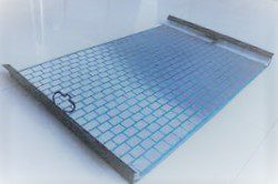
Three-dimensional shale shaker screens are perforated, plate screens with a corrugated surface that runs parallel to the flow of fluid. This configuration provides more screen area than the two-dimensional screen configuration. The different types of three-dimensional screens are:
- Pyramid
- Plateau
Figure 1 shows the difference between two- and three-dimensional screens.
Shale Shaker Screen Specifications
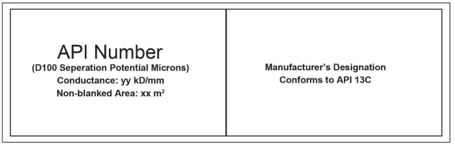
The API (RP13E) recommends that all screens be labeled with the screen name, separation potential, and flow capacity. Optional screen labels include U.S. sieve number, aspect ratio, and transmittance. Table 10-5 depicts how screens can be labeled using all descriptors
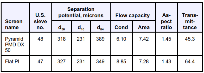
The following definitions apply to Table 4.
Separation potential
The percentage of particles of the specific size, in microns, that can be removed.
Examples:
- d50 Particle size in microns where 50 percent of the particles are removed
- d16 Particle size in microns where 16 percent of the particles are removed
- d84 Particle size in microns where 84 percent of the particles are removed
Note: d50 is listed first in most tables because it is the most common.
Figure 2 demonstrates separation potential.
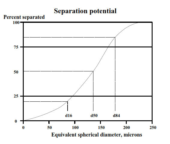
The D subscript refers to the percent removed so that in a D16 cut, 16% of the stated micron size particles are removed and D84 is the micron size where 84% of the solids are removed. These D sizes are determined from a particle size distribution of the feed liquid and solids discharge. The combination of the screen D50 and the ratio of the D84 divided by the D16, gives a more complete picture regarding separation efficiency.
The D84 / D16 ratio indicates how exact or “sharp” the cut point is — where all of the solids down to a certain size are removed but none of the smaller particles are removed. A square mesh market-grade shale shaker screens makes a sharp almost 100% cut point at the opening size of the screen and the D50 , D84 and D16 values are all the same micron size as the screen opening. Therefore, the D84 /D16 ratio is 1.0 for square market-grade screens. It is most desirable to have screens with a D84 / D16 ratio near 1.0; values above 1.5 are undesirable.
Flow capacity
The two parts of flow capacity include conductance (Cond) and non-blanked (open space) area (Area).
- Conductance is the amount of open space between wires in kilodarcies per millimeter.
- The non blanked (open space) area is the total effective screening area per panel in square feet.
The conductance of a screen, the amount of fluid that will pass per unit time, is an important parameter in selecting the minimum screen size that can be operated under the given drilling conditions. Under the old system manufacturers would give the percentage open area and at the same time claim an optimum screen life. These two properties are obviously counteracting as a large open area can only be obtained by using thinner wires. In the new API 13 C system, a test must be performed where the actual permeability of the shale shaker screen is determined using standard oil and a laminar flow pattern. Both the permeability and the open area must be printed on the screen label. An example of a screen label is given below.
Aspect ratio
The volume-weighted average length-to-width of the screen openings.
Transmittance
The net flow capacity of individual screens; the product of conductance and unblocked screening area.
Shale Shaker Screens blinding, plugging
Screen blinding occurs when grains of solids being screened lodge in a screen hole. This often occurs when drilling fine sands, such as in the Gulf of Mexico. The following sequence is often observed during screen blinding.
- When a new screen is installed, the circulation drilling fluid falls through the screen in a short distance.
- After a time, the fluid endpoint travels to the end of the shaker.
- Once this occurs, the screens are changed to eliminate the rapid discharge of drilling mud off the end of the shaker.
- After the screens have been washed, fine grains of sand that are lodged in the screen surface can be observed. The surface of the screen will resemble fine sandpaper because of the sand particles lodged in the openings.
One common solution to screen blinding is to change to a finer or coarser screen than the one being blinded. This tactic is successful if the sand that is being drilled has a narrow size distribution. Another solution is to change to a rectangular screen, although rectangular screens can also blind with multiple grains of sand.
Blinding – the “plastering” of soft material over and in the mesh, rendering it blocked.
Remedy = wash with high-pressure fluid using the base fluid of the drilling fluid. If this fails, fit coarser screens temporarily.
Plugging – the blocking of the mesh by a particle (usually sand) fitting into the pore throat of the mesh.
Remedy = wash with high-pressure fluid using the base fluid of the drilling fluid. This is best done from beneath the screen (after removal). It is often successful to place a finer screen on to reduce the “near size” plugging.
How To Increase Shale Shaker Screens Life?
Screen Life of fine mesh screens varies widely from design to design, even under the best of conditions, because of differences in operating characteristics. Screen life can be maximized by following these general precautions:
- Keep screens clean.
- Handle screen carefully when installing
- Keep screens properly tensioned.
- Do not overload screens.
- Do not operate shakers dry.
Screen capacity, or the volume of mud that will pass through a screen without flooding, varies widely depending on the shale shaker model and drilling conditions. Screen mesh, drilling rate, drilling fluids type, weight and viscosity, drilling bit type, formation type, — all affect throughput to some degree.
The mesh of the screen in use is also directly related to shaker capacity because (in general but not always) the finer a screen’s mesh, the lower its throughput. Drilling rate affects screen capacity because increases in drilled solids loading reuse the effective screen area available for mud throughput.
Increased viscosity, usually associated with an increase in percent solids by volume and/or increase in mud weight, has a markedly adverse effect on screen capacity. As a general rule, for every 10% increase in viscosity, there is a 2-5% decrease in throughput capacity.
Final Words
Modern shale shakers have double-deck screen arrangements. The coarse screen should be run above the fine screen. Selection of the screen should normally be so that during operation 2/3 of the screen area is wet, 1/3 is dry, though this can vary dependent on the mud and shale shaker types. Note that each deck should have the same size screen over its whole area.
There are both advantages and disadvantages in the early removal of the majority of solids. The
advantages include:
- Minimization of recirculation of cuttings down hole
- Prevention of overloading of the cyclones
- Prevention of generation of fines which cannot be removed by cyclones
- Elimination of bit bottom fill
The disadvantages include the loss of fluid if the screen mesh is too fine. This is particularly important when drilling in the top part of the hole where large volumes of fluid are circulated Shale shakers are the primary solids control units for removing drilled solids. When drilling with unweighted drilling fluid there is no theoretical lower limit to screen size.
All the fluid returned from the hole has to be screened, so the required capacity should be set at greater than the maximum pump capacity in order to allow for all the returns to passing over the shakers. Usually, 150% of the maximum pump capacity is considered adequate.
Correct design of the flow distribution to the shakers is very important so that each shaker installed can screen its fair proportion of the mud returns. Be aware that whole mud losses may occur when initially circulating cold muds over fine screens. Either bring up circulation gradually or fine down shaker screens gradually.
Lost Circulation Material
- Do not bypass the shakers to avoid screening out the LCM material.
- Scalping shakers can be used to recover LCM when high concentrations are continuously required in any of drilling fluids types, provided.
- Cuttings size distribution is sufficiently fine to pass through the scalping screens.
- Solids loading rates do not negatively impact the performance of the downstream shakers and cause solids build-up in the active system.