How Drill String Design In Horizontal Wells Differs From In Vertical Wells
The design approach in high inclination and horizontal wells differs from the approach in vertical wells in the following respects:
- In high inclination / horizontal wells, traditional BHA components are often eliminated. Drilling Bit weight is likely to be applied by running normal weight drill pipe in compression, a practice never recommended in vertical holes.
- For a given measured depth, surface tension load from hanging weight decreases in a high inclination / horizontal well due to wall support, but torque and drag required to move the drill string are higher compared to vertical holes. The load limit for the drill string will be its tensile capacity in a vertical hole, but is more likely to be its torsional capacity in horizontal and extended reach wells.
- In vertical wells, loads are calculated based on hanging weight. Friction effects are often small and are traditionally ignored. In horizontal wells, friction effects will probably be large enough that they cannot be ignored.
- Drill string design for vertical holes is a once-through calculation. In horizontal and ER wells, drill string design is an iterative process.
The objectives of drill string design in horizontal wells are:
Provide adequate weight on bit without buckling the drill pipe or heavy weight drill pipe. Ensure that the components in the drilling assembly are not subjected to mechanical loads that exceeds their design limitation
Thus the problem is to determine where and at what bit weight the drill pipe will first begin to buckle. If this bit weight is sufficient to drill the well, buckling can be avoided by staying below it. If the bit weight needed causes the pipe to buckle, then heavy weight drill pipe should be run in the buckled sections.
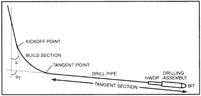
As was mentioned before, the critical buckling load in a curved section is greater than that across tangent and vertical sections. Therefore, buckling of drill pipe will initiate in the tangent section (below the tangent point) or above the kickoff point.
The maximum weight on bit without buckling the drill pipe can be calculated in two steps:
1) Calculate the maximum weight that can be applied on the bit without buckling the drill pipe below the tangent point
If the tangent angle of a curved or build section is less than horizontal, the highest mechanical compression in the drill pipe will occur in the joint at the top of the bottom hole assembly.
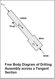
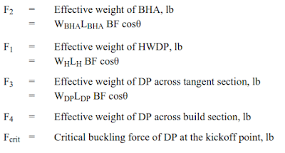
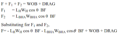
The force F1 is the effective weight of the HWDP and
The force F2 is the effective weight (along the hole axis) of the BHA.
The force Fcrit is the critical buckling force of the drill pipe at the top of HWDP which is equal to the maximum mechanical compressive force that can be applied (slacked off) without buckling the drill pipe.
Taking a force balance along the hole axis, The maximum weight on bit that can be applied without buckling the drill pipe is
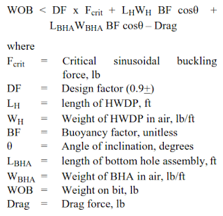
If the hole below the tangent point is horizontal, then cos 90=0 and
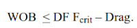
For sliding mode drilling the drag force is calculated as was described previously. For rotary mode drilling, the drag force is small and is assumed to be zero.
2) Calculate the maximum weight that can be applied on the bit without buckling the drill pipe above the kickoff point.
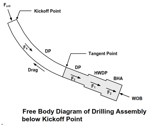
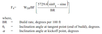
A free body diagram of the drilling assembly below the kick-off point . The forces in the diagram are defined as follows:
A simpler way of calculating the effective weight of the drill pipe across the build section is by using the following equation,
The lower of the two weights is the correct weight to be used for drilling.
Calculation of Axial Mechanical Forces In High Inclination / Horizontal Wells
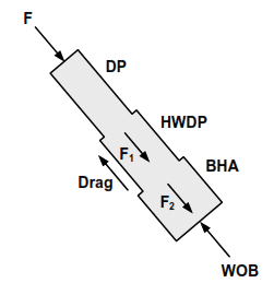
In drill string design of horizontal wells, the drilling engineer may want to check if the applied WOB will buckle the drill pipe at the top of BHA.This is accomplished by drawing a free body diagram of the BHA showing only the mechanical forces as shown above.
The mechanical force F (the mechanical force trying to buckle the drill pipe and it is not the total or actual axial force) at any point in the drill pipe is calculated by making a force balance. The actual axial force is calculated by including the hydrostatic pressure forces acting on the shoulder areas & dividing the actual force by the metal area of the drill pipe.
Taking a force balance,
- If drilling in the rotary mode, the drag force is zero.
- If the calculated value of F is less than the critical buckling force Fcrit of the drill pipe, then the drill pipe will not buckle.
- If F is greater than the Fcrit, then the drill pipe will buckle.
Summary for high angle wells Drill String Design

- Calculate the drag forces and torque by using a computer program such as Landmark Well Plan.
- Calculate the sinusoidal critical buckling force below the tangent point and above the kickoff point.
- Calculate the maximum WOB that can be applied without buckling the DP below the tangent point
- Calculate the maximum WOB that can be applied without buckling the DP above the kickoff point. Take the lower of the two values. If the WOB is not sufficient then add more HWDP in the drilling assembly.
- Calculate the actual forces on DP below the tangent point and above the kickoff point. Include bending forces and check for fatigue if the build rate is high. If the actual forces exceed 90% of the DP yield strength, then select a DP with higher yield strength.
- Check the actual torque at all depths and make sure it is less than the makeup torque of DP