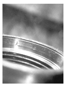
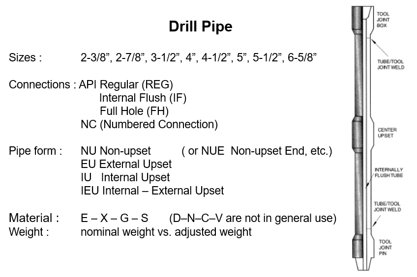
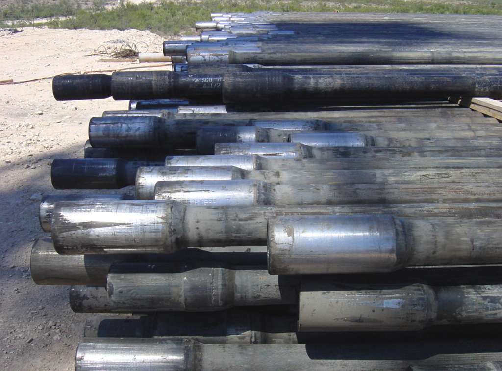
A drill pipe is a seamless tube with special threaded couplings called tool joints. It is used to transmit rotary power from the surface to the bottom of the hole and to supply fluid at sufficient volume and pressure to the drill bit. Typically, it is the most extended & significant section of the Drill String Components on the drilling rigs. Each joint comprises the tube body and the Tool Joint (connection). Figure 1 is a picture of 5″ DP – the tool joints are at each end. This article will discuss API drill pipe specifications, types, descriptions, classifications, connections, and thread types.
Manufacturing Process
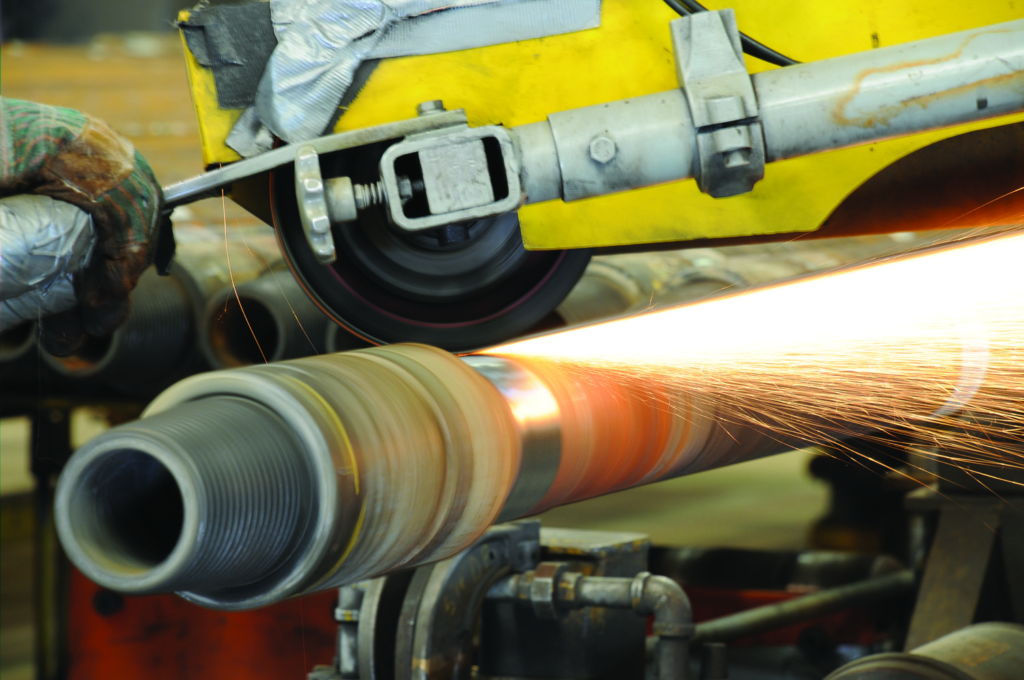
Manufacturing processes used for pipes involve a series of steps. Once the material is selected, it goes through a rigorous manufacturing process, including heating, forging, and machining, to shape it into the desired size and specifications. The drill pipe is then carefully inspected for defects or imperfections and undergoes various quality control tests. Finally, the pipe is coated or treated to enhance its corrosion resistance.
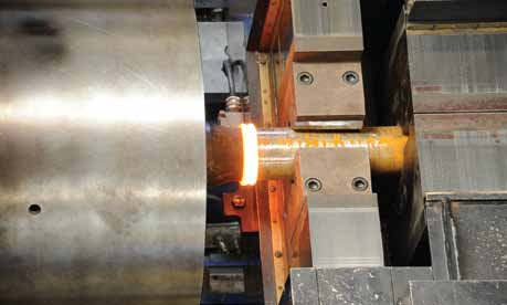
The next step is preparing the tool joints. The tool joints come in green tubes and undergo quench and temper heat treatment before cutting into the box tool joint (female) and pin drill pipe tool joint (male). Then comes the welding step. Generally, the two main methods for welding tubes and tool joints are rotary inertia and direct drive friction welding.
- Direct drive friction welding is a cutting-edge technique that offers accurate process control and monitoring of up to 1000 times per second. This leads to a high-quality weld that may not need a full heat treatment quench and temper regime. It is a solid-state welding process that joins two distinct metal pieces by exerting axial pressure while simultaneously rotating one of the parts at a high speed. The friction between the two materials melts them at the interface, resulting in a robust bond.
- On the other hand, in the rotary inertia method, the tool joint is rotated at high RPMs and then pressed onto the stationary tube’s upset end. This generates heat and force that weld the two parts together. The weld line is only visible under a microscope after removing excess material.
Both methods have proven effective. Inertia friction welding is the traditional option, while direct drive friction welding is a more modern and controlled alternative.
Types of Drill Pipe
Different types of pipes are available to suit various needs and requirements. From heavy-weight to light-weight.
The common types are:
- Regular Pipe
- Heavy Weight Pipe
- Light Weight Pipe
Heavy-Weight Drill Pipe
The Heavy-weight drill pipe (HWDP) has a heavy wall pipe body, which provides extra strength compared to the regular type. The tool joints are also reinforced. One key feature of HWDP is the wear pad, a hardened steel sleeve near the tool joint. This wear pad helps to prevent excessive wear and prolong the life of the pipe by providing improved stability and reducing fatigue failures. We mainly use HWDP in the drill string transition zone to avoid drill string failure.
Light Weight Drill Pipe
Thinner pipe, also known as light-weight drill pipe is designed with reduced dimensions. They typically have a smaller nominal outside diameter and reduced wall thickness than the regular type. This is because it will provide enhanced flexibility and agility for specific drilling operations that may require more maneuverability. Its common sizes include nominal outside diameters ranging from 2 3/8 to 4 1/2 inches, with corresponding wall thicknesses varying from 0.125 to 0.337 inches.
This type is engineered to withstand the tension, compression, and torque forces involved in drilling. That’s why it finds applications in directional drilling, ERD & critical deep drilling operations, where precise steering and navigation are crucial. It is also suitable for shallow wells and areas where weight restrictions are a concern, such as offshore platforms.
Drill Pipe Specifications
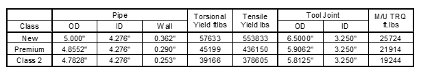
According to API Drill Pipe Specification, we can describe the pipe in six terms. For example, a 5″ drill pipe is 5″,19.5 Ib/ft, G, XH, NC50, Premium.
What is The Common Drill Pipe Ranges
The String is composed of multiple sections of Pipes. A “stand” typically comprises two to three drill pipe joints, each around 60 to 90 feet in length. Each joint of pipe is referred to as a “single.” According to API, there are three ranges of drill pipe length: R1, R2, and R3.
Drill Pipe Class
Five classes of drill pipe indicate the amount of wear a pipe joint has sustained during its lifetime.
- New
- Premium or class 1
- Class 2
- Class3
- Scrap
All new pipes become premium class as soon as they are used. The new pipe indicates it is directly from the manufacturer and has never been used. As soon as a joint of the new pipe is picked up for use on a rig, it is re-classified as premium or class 1 pipe. Interestingly, this allows the manufacturers a broader set of tolerances, with the pipe having to conform to the requirements for Premium grade rather than the new specification.
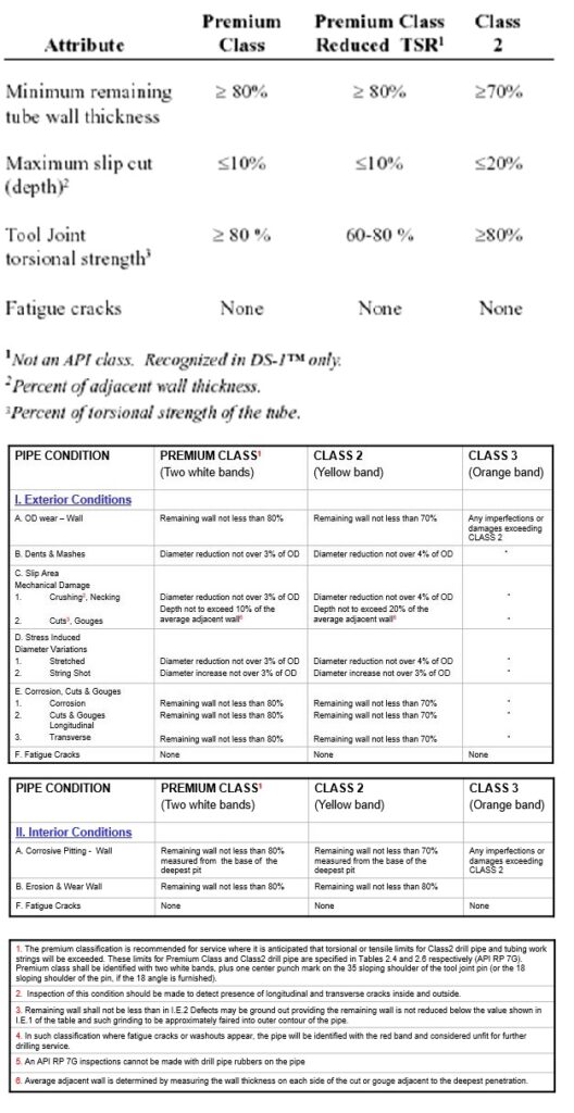
Criteria For Determining The Class
Once the drill pipe has been used, normal wear and other use-related defects cause it to lose some of its original strength. API has developed inspection criteria to determine the extent of damage. These criteria are used to assign the pipe to “classes” according to the extent of the damage. The inspection examines the following conditions with all the criteria having to be met for a drill pipe to gain the specific class.
- OD wall wear.
- Fatigue cracks.
- Dents and mashes.
- Stress-induced diameter variations. Stretched or shot.
- Internal corrosion and pitting.
- Internal erosion and wear.
- Corrosion cuts and gouges, longitudinal and transverse.
- Internal fatigue cracks.
- Any evidence of fatigue cracks or washouts and the pipe is designated as scrap.
- Slip area mechanical damage. Crushing, necking, cuts and gouges.
Identification Marks
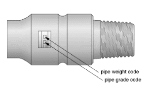
Code marks, which are stenciled on the tool joint pin to identify drill pipe and string, record the following information:
- Manufacturers’ symbols.
- Month connections welded on.
- Year connections welded on.
- Pipe mill code.
- Pipe steel grade.
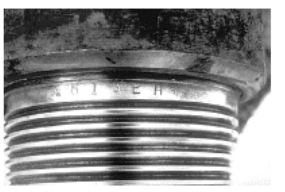
Sometimes a mill slot plus one circumferential groove, about 3/8″ (9·5mm) wide, is milled onto the pin end of drill pipe grades higher than “E” (see Figure 2.1.3), but be in the habit of checking, as this can vary from contractor to contractor and rig to rig. A series of letter and number codes will be present on all API drill pipes, giving manufacturing data such as date of manufacture, manufacturer’s code, and the grade of steel – see Figure 2.1.8a & b.
API re-facing benchmarks show the position of the original shoulder so an inspector can determine if too much re-facing has occurred – Figure below.
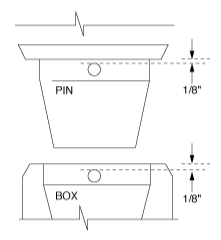
The re-facing benchmark is positioned 1/8″ from the makeup face. The tolerance on this measurement is ±1/16″. Once re-facing has taken place such that 1/16″ of the make-up face has been removed, the joint must be re-cut or belled, and split boxes become a risk.
The API benchmark is only present at one location around the circumference of the tool joint. The API benchmark will not show if re-facing is uneven around the makeup face area. Proprietary benchmarks are available. The figure below shows the Grant-TFW benchmark. As it is a continuous line, it shows how perpendicular the re-facing is and how much has occurred.