As was discussed in the previous sections (Drill String Design), the drill string in vertical wells is designed so that the mechanical weight on the bit is provided by the drill collars. The buckling neutral point should always be below the top of the drill collars to prevent any buckling to the DP and HWDP.
The drill pipe in vertical hole should always be in tension because drill pipe has very low resistance to buckling. A small mechanical compressive force of few thousand pounds will buckle the drill pipe. It is common practice in drill string design that the drill pipe should not be rotated in a buckled condition as this will cause rapid fatigue drill string failure.
In drilling inclined and horizontal wells there are two additional factors, which are not present in vertical wells, that must be considered. These are
- The frictional forces between the drill string and the hole.
- The ability to use the drill pipe or HWDP to provide weight on the bit without buckling.
Because of the hole geometry some or all of the weight of the drill string in inclined or horizontal wells is exerted on the low side of the hole. SO
- This will create a frictional force or drag between the drill string and the hole that will require additional force or pull to move the drill string up or down the hole.
- The frictional force will also increase the torque that is required to rotate the drill string.
The second factor that must be considered in the design of the drill string is the fact that drill pipe can be used in compression to provide weight on the bit. In inclined and horizontal wells the drill pipe can tolerate significant levels of compression without buckling in small-diameter holes. The reason that the drill pipe in inclined holes is so resistant to buckling is that the hole is constraining and supporting the pipe throughout its length. The low side of the hole forms a trough that resists even a slight displacement of the pipe from its initial straight configuration. The effect of gravity and the curving sides of the hole form a restraint against buckling.
Now we shall go through the following Subjects:
Drill String Torque Calculations
We can define the drill string torque,as it is the rotational force that is required to overcome all the frictional forces between the drill string and the formation while drill string rotation.
Drill String Drag Calculations
Consider an object of weight W is resting on a horizontal plane. In order to slide the object a force Ft must be exerted to overcome the force of friction Ff between the object and the plane surface.
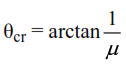
Critical Hole Angle
When the weight component of the drill string in the direction of the hole axis is equal to the drag force resisting downhole movement, the drill string is not able to slide down hole by its own weight and when drilling in the sliding mode the drill string will require pushing with pipe higher in the hole. The angle at which down hole movement becomes impossible is called the critical hole angle,
Determination of Friction Coefficient
The coefficient of friction determines how much of the normal force is transformed into drag or torque and it is an important factor in calculating Torque And Drag in a wellbore.
Factors that Affect Torque and Drag
When planning a 3D well trajectory, one of the most important considerations is torque and drag. If the torque and drag are not carefully considered, the drill string might fail. The torque and drag model used makes special assumptions that simplify the analysis and are used to model real drill strings. The most important factor influencing the torque and drag forces is the hole curvature. The well path should be redesigned with a smaller build-up rate if the drill string seems to fail when simulating these forces during the design stage. There are many causes for excessive torque and drag such as: sliding friction, tight hole, collapsing or swelling clay/shale, key seats, differential sticking and cuttings build-up. The minimum curvature method assumes the bending part in the equilibrium equation used to calculate torque and drag is discontinuous at survey stations. Some authors mean this is one of the main weaknesses of using the minimum curvature method. Due to the missing bending stresses, the method might not represent the real drill string configuration.
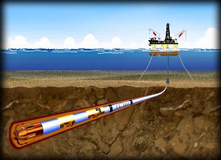
Drill String Design for High Angle and Horizontal Wellbores
The design approach in high inclination and horizontal wells differs from the approach in vertical wells in the following respects:
- In high inclination / horizontal wells, traditional BHA components are often eliminated. Drilling Bit weight is likely to be applied by running normal weight drill pipe in compression, a practice never recommended in vertical holes.
- For a given measured depth, surface tension load from hanging weight decreases in a high inclination / horizontal well due to wall support, but torque and drag required to move the drill string are higher compared to vertical holes. The load limit for the drill string will be its tensile capacity in a vertical hole, but is more likely to be its torsional capacity in horizontal and extended reach wells.
- In vertical wells, loads are calculated based on hanging weight. Friction effects are often small and are traditionally ignored. In horizontal wells, friction effects will probably be large enough that they cannot be ignored.
- Drill string design for vertical holes is a once-through calculation. In horizontal and ER wells, drill string design is an iterative process.