In case of a drill string failure, such as pipe washout or twist-off, it is crucial to determine the cause of the failure to prevent it from happening again. This text covers the most common failure mechanisms, of which there are over a dozen, and provides a general understanding of what to do in each case. We have named most of the failure mechanisms according to common usage or the type of load that causes the failure. Still, it is important to note that several other factors besides load type and magnitude can also play a role in failures caused by a specific mechanism. The failure mechanisms covered in this text include:
- Fatigue
- Tension
- Torsion
- Combination tension/torsion
- Burst and collapse pressure failures
- Split box failures
- Weld-related failures
- Sulfide stress cracking
- Stress corrosion cracking
These failure modes account for the vast majority of drill string failures. In fact, drill pipe tube fatigue and bottom hole assembly connection fatigue combined probably account for 80% of all drill string failures. Thus, any serious attempt at reducing drill string failures must focus on these two mechanisms.
Fatigue
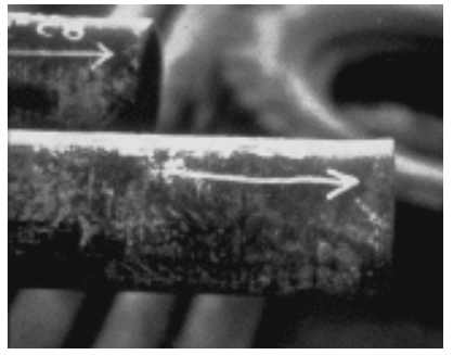
Fatigue is damage caused by repeated cycles of stress at a level below the material’s tensile strength. In drill strings, this occurs when the drill string is rotated while bent or buckled or from drilling vibration. Fatigue can occur at cyclic stresses as low as 20% or less of the yield strength of the drill string component. Fatigue damage is cumulative, and almost all drill string components will eventually succumb to fatigue unless they are first worn out or lost for other causes. “Washouts,” with the exception of those caused by connection leaks, are primarily the result of fatigue cracks. When the crack penetrates the drill pipe tube wall or drill collar box, drilling fluid leaks through the crack and eventually erodes it into a hole. The hole is called a “washout”.
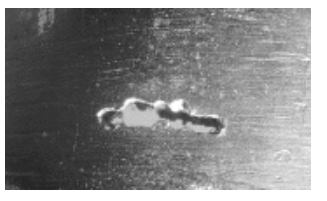
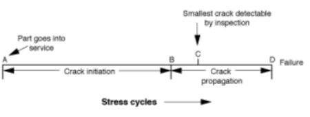
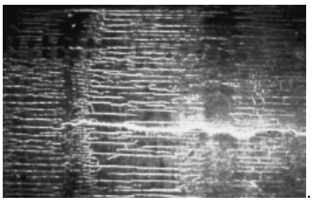
Fatigue damage is a gradual process that starts with a microscopic structural alteration in the metal crystals subjected to high-cycle stress. The damage then progresses until a tiny crack appears. The crack gradually expands under the repeated stress cycles until it is either detected through inspection or results in component failure. Figure 2 illustrates the life cycle of any component that undergoes fatigue. The percent of total fatigue life consumed in getting to point “B” is estimated at between 50% and 90%, and no reliable method exists for identifying a fatigue-damaged component until point “C” is reached. Therefore, most of a component’s life may be gone before any indication of fatigue damage can be seen. This will make fatigue failures challenging to prevent unless we are vigilant.
Tensile Drill String Failures
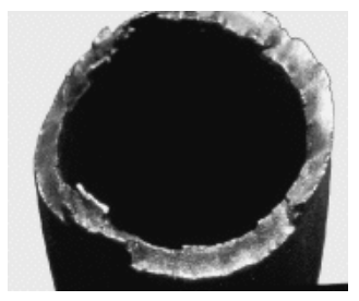
Tensile failures occur when the tensile load exceeds the capacity of the weakest component in the drill string, which is usually a drill pipe in the upper section of the borehole. Occasionally, a drill pipe tool joint pin will be the tensile failure location if the connection was made up beyond the recommended torque.
A drill pipe tensile failure may be recognized by the fracture surface, which, in most cases, will be “jagged” and oriented at 45° to the axis of the pipe. The drill pipe will usually be “necked down” to a smaller diameter immediately adjacent to the fracture (Figure 3).
Preventing failures due to tension is a relatively simple process:
- Select a drill pipe capable of carrying the anticipated loads, a margin of overpull, and a design factor.
- Use a marking system that shows drill pipe weight and grade. Please verify the grade and weight by checking the pin markings.
- When using multi-grade strings, employ a groove system to identify pipe grade. This helps guard against mixing grades.
- Ensure the drilling rig weight indicator is calibrated correctly and does not exceed the allowable tensile load.
Torsion Failures
API “standard” tool joints are about 80% as strong in torsion as the tube to which they are attached. Therefore, torsion failures will occur in tool joints in almost all cases.
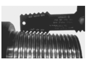
Torsion failures initially appear as either a “stretched pin” (a pin with an elongated thread, as shown in Figure 4) or a “belled box,” which is demonstrated in Figure 5. Which fails first will depend on whether the pin or box is weaker. In extreme cases, the box may be split longitudinally, or the pin may be pulled apart at the first engaged thread nearest the shoulder.
Torsion design is a straightforward process. Pin ID and box OD determine tool joint torsion strength, and the weakest component will govern. The rules to follow are:
- Select tool joint ID and OD so that the recommended tool joint makeup torque exceeds the maximum anticipated torsion. Allow some tolerance for box OD wear.
- Check the tool joints to ensure they meet these dimensional requirements and show no signs of prior torsion yielding (stretched pins, swelled boxes).
- Make sure that the torque application device is calibrated correctly and rigged.
- Use API tool joint compound with a friction factor between 0·95 and 1·05, or adjust the applied torque accordingly.
- Make up the connections to the recommended torque.
- Do not exceed makeup torque during drilling (avoid downhole makeup).
Burst & Collapse Drill String Failure
It’s important to note that drill pipe tubes have a limit to the amount of pressure they can handle. If this limit is exceeded, there is a risk that the tubes may burst or collapse. Burst is most likely to occur high in the hole. Collapse is likely deep in the hole when the drill pipe has been evacuated for drill stem testing. Collapse capacity must be derated for simultaneous tension. The design recommendations in this Part should be followed to prevent these failure mechanisms.
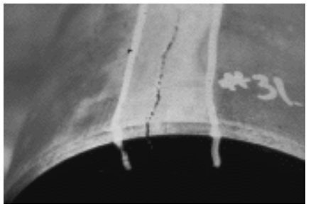
Split Box
A split box (Figure 7) can be considered a particular type of fatigue failure. If a tool joint is subjected to bending, as in a severe dogleg, tensile hoop stress will be created in the box as the bending tries to force the pin sideways out of the box. As the pipe is rotated, the hoop stress will cycle up and down, and this can ultimately form a longitudinal fatigue crack in the box if the loading lasts long enough or is severe enough. Any condition that increases the tensile hoop stress in the box can accelerate this fatigue mechanism. The most likely culprits are:
- Refacing of either box or pin: A new rotary-shouldered connection pin and box are nearly fully engaged radially when the shoulders come into contact. Refacing sets the shoulders back from their original positions, which has the same effect as enlarging the pin or reducing the box pitch diameters. Either of these effects will create undesirable tensile hoop stress in the box and could contribute to a split box failure.
Other Factors
- Heat checking: Heat checks are longitudinal cracks that can occur when the box is rotated and pressed hard against the formation wall. These cracks are sharp and oriented in a longitudinal direction, making them stress concentrators and potential starting points for longitudinal box cracks. The presence of heat checks indicates that the tool joint box has been exposed to severe side loads.
- High doglegs: Any dogleg severe enough to create heat checking or a split box will also be highly detrimental to the fatigue life of the tube.
- Over-torqued connections: Over-torqued connections will also contribute to a split box failure since “box swell,” a classic indicator of torsion failure, means the box has been stressed past its yield point in the hoop direction.
Weld Related Drill String Failures
With the apparent exception of tool joints to tube welds, welded components in the drill string should be avoided if possible. Most components are made from relatively high carbon steels that are heat treated to achieve desired mechanical properties. Welding permanently alters these properties unless the component is reheat-treated, which is usually impossible in the field. Even when strength is not a significant concern, welds and heat-affected zones can be highly brittle unless the welding process is carefully designed and executed. If it is essential to run a welded component, the following procedure should be followed:
- Ensure that production welding is done only by qualified welders and precisely as required by the procedure.
- Have a specialist design a welding procedure to control all the necessary variables to obtain a weld with the desired properties. These variables will include the welding process, position, pre-heat, post-heat, feed rates, filler metal specification, and many others.
- Suppose a welder other than the one who made the initial weld is used. In that case, the welder must also be qualified for the specific procedure. Welder qualification is done using a test piece in the same way as procedure qualification.
- Have the procedure qualified by following it exactly as written to weld a test piece, then confirm that all desired properties are met in the finished product. This almost always requires destructively testing the test piece.
Sulfide Stree Cracking
The Problem
Sulfide stress cracking (SSC) can occur in the presence of hydrogen sulfide (H2S). During this process, H2S reacts with iron in the drill pipe to create atomic hydrogen.
Fe + H2S = FeS + 2H
Some free atomic hydrogen may diffuse into the steel and collect at high-stress locations such as inclusions and along grain boundaries.
Stress corrosion cracking (SCC) is a complex mechanism responsible for component failure. The likelihood of a component failing due to SCC is influenced by various factors, not all of which are related to the metal of the part. Although some metals are resistant to SCC, very few drill string materials are completely immune to SCC. However, it is generally true that the higher the tensile strength of a steel, the more susceptible it is to SCC.
Specialized tools are of particular concern in hydrogen sulfide service as their designers need to cram a lot of gadgetry into limited space and still make a tool capable of carrying high loads. This means that material strength will often be pushed to the limits, which means that metal will also be highly susceptible to SSC.
The National Association of Corrosion Engineers (NACE) published the standard reference work MR-01-75, titled “Sulphide stress cracking resistant metallic materials for oilfield equipment,” for sound engineering documentation on SSC.
Controlling stuck pipe (SSC) during drilling H2S-bearing formations involves monitoring and controlling various factors that can cause it. To reduce the likelihood of SSC, we can take two types of initiatives: first, we can suppress and manage the factors that work against us, and second, we can identify and address any potential risks that may lead to the occurrence of SSC.
Suppressing The Reaction Between Steel And H2S:
The lower the steel/H2S reaction rate, the less free hydrogen is around to endanger the string. The reaction is suppressed by following the guidelines in NACE MR-01-75, which requires drilling overbalanced and at least one of the other three steps listed below:
- Drill overbalanced. This limits the influx of sour formation fluids and presents fewer H2S molecules to react with the steel in the string.
- Use H2S scavengers in the drilling mud. These react with and neutralize some free hydrogen sulfide that makes it into the wellbore.
- Using oil-based drilling fluid, OBM will coat the surface of the steel and retard the corrosion reaction that liberates the hydrogen.
- Keep pH elevated. The hydroxyl ions in a caustic drilling mud react with some of the free hydrogen that may be liberated in the reaction of the H2S with the steel. NACE MR-01-75 requires a minimum pH of 10.
Reducing Susceptibility To SSC
- Use G or lower grade pipe if it will carry the loads: The more complex and vital the material is, the more likely it is to fail, other things being equal. Since API tool joints are more robust than G-grade pipe, little is probably gained by limiting the pipe grade to E or X.
- Use quenched and tempered (Q&T) material: Other things equal, a Q&T microstructure is more resistant to SSC. All grades may be Q&T or normalized and tempered (N&T). Grade E is allowed to be normalized (only) as well. Few drill strings are anything except Q&T, but it is a good idea to ask to see the material certificates.
- Check specialized equipment material against NACE MR-01-75: Ask the specialized tool manufacturer to review his material test reports (MTRs) and compare them against the NACE document. Demand a detailed report supported by a technical backup. (Don’t settle for a letter saying “everything is OK.”) Ask for a copy of the MTRs and at least give the impression that you will examine them in detail (this will get them looking at the problem more intensely). Get an expert’s help in evaluating the answers.
Stress Corrosion Cracking & Drill String Failure
Stress Corrosion Cracking (SCC) is a mechanical environmental failure mechanism that mainly attacks stainless steel (non-magnetic) drill string components. API drill pipe and drill collars, which are low-carbon drill string materials, generally do not corrode in most drilling environments. Like sulfide stress cracking (SSC), SCC is a complex mechanism. Galvanic corrosion cells between grain boundaries are believed to promote rapid intergranular corrosion in parts experiencing simultaneous tensile stress.
This combined stress and corrosion can rapidly form and extend intergranular cracks in susceptible material. Thus, the mechanism is given its name. Preventing SCC in drill strings mainly involves using stainless steels that are not susceptible to attack. Ferritic stainless steels are generally more corrosion-resistant than austenitic stainless steels due to various factors. SCC has become less of a problem recently because specialized tool manufacturers have adopted more resistant materials.