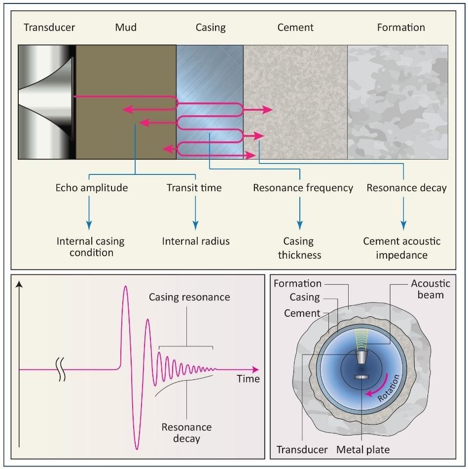
The Cement evaluation tool (CET) uses ultrasonic acoustic pulses from a rotating transducer and measures radially instead of axially. The transmitter emits ultrasonic pulses between 200 and 700 kHz and measures the received ultrasonic waveforms reflected from the internal and external casing interfaces.
The rate of decay of the waveforms received indicates the quality of the cement bond at the cement/casing interface, and the resonant frequency of the casing (Casing Specs) provides the casing wall thickness required for pipe inspection (Drill Pipe Inspection). Because the transducer is mounted on the rotating sub, the entire circumference of the casing is scanned.
Note: Proper interpretation of the Cement Evaluation Tool (CET) data requires specialists, you will need to engage the contractor.
Cement Evaluation Tool CET- PET Tool Description
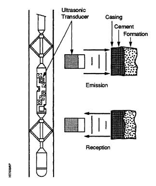
The pulsed echo tools employ an ultrasonic (300 to 600 kHz) pulse, of approximately 10 μs duration, focused perpendicular to the casing. The pulse is generated by some 8 transducers, doubling up as receivers, arranged in a helical pattern at the outside of the sonde. A ninth transducer faces downward at the bottom of the tool to measure the sound velocity in the well-bore fluid in combination with a reflector placed at a known distance from this transducer.
The ultrasonic beam of each transducer is partly reflected and partly transmitted at each of the interfaces between fluid, pipe cement (Cementing in drilling), and formation. The amount of energy reflected at each interface is related to the reflection coefficient, which is a function of the acoustic impedances of the various materials. As these parameters are known or can be measured directly for well-bore fluid, casing material, and formation rock, the one (unknown) for the media in the annulus can be derived from the energy portion picked up by the transducer in the receiver mode. The nature of the annular fill can then be inferred from the recorded acoustic impedance.
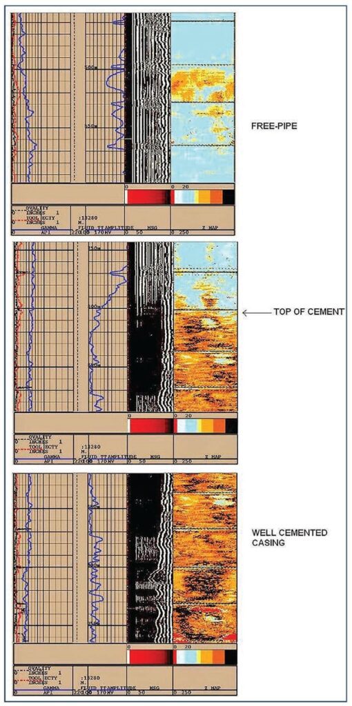
Log evaluation
The log generated by a cement evaluation tool shows three or sometimes four distinct sections in the wavetrain at the receiver.
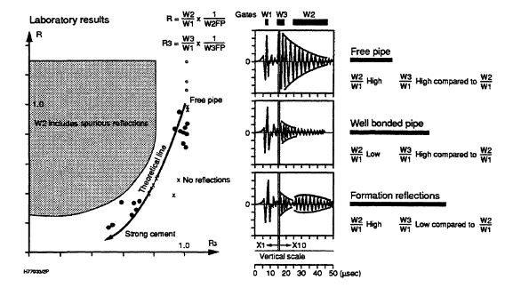
The first represents the direct reflected energy from the inner pipe surface. With a known velocity in the well-bore fluid, its arrival time is used to calculate the distance between the sonde and inner pipe surface, whereas the amplitude gives a measure of attenuation in the fluid. Summation of this distance from two transducers phased at 180 degrees and the tool diameter gives the inner pipe diameter. As the 8 transducers are phased 45 degrees one pulse will result in 4 diameters from which the average is calculated. The difference between the largest and smallest diameter is a measure of the pipe’s circularity, while the difference between transducer-pipe distances, inferred from 180 degrees of phased transducers, indicates the degree of eccentricity of the tool.
The second and third interval of the received energy spectrum is rectified and integrated over a given time interval to give the thickness of the annular media and to yield its acoustic impedance respectively. The thickness of the casing is needed as input in the process
The fourth interval, sometimes called secondary reflection, would indicate formation arrival after suitable compensation imposed by the intervening media. It will be present in cases where the cement sheath is thin and the pipe is well centralized (Casing Centralization) in a gauge hole. Also, a large acoustic impedance contrast between annulus media (cement) and formation favours formation reflection. Its presence is undesirable as it overlaps the third interval and thus interferes with and complicates the evaluation of the log.
Adverse effects on pulse echo- cement evaluation tool
Several conditions and parameters have an adverse effect on the interpretation of the pulse-echo cement evaluation.
- The presence of a micro annulus and, more important the media it contains, will adversely affect the tool’s response when the size is of the same order of magnitude as the wavelength of the pulse in the micro-annulus media. If gas filled the sensitivity is much higher than when containing a liquid, proportional to the wavelength variations. In general, a fluid-filled micro annulus of less than 0.2 mm will have only a marginal effect, but for gas a size of 1 μ already creates a serious impediment.
- Pipe coatings and corrosion products affect log interpretation by severe attenuation of the signal (as in gas).
- Gas bubbles in the annular contents (e.g. caused by an influx in the gelling and setting stage) significantly reduce the acoustic impedance and thus might lead to an interpretation of imperfect cement fill.