
Well cementing plays a very important role in the construction, completion, and abandonment of wells since the cement performs vital functions in supporting the casing and drilling wellhead equipment. The casing cannot perform the functions it is designed for, described elsewhere unless effectively cemented in place. The cement forms an impermeable barrier to the passage of gasses and fluids and enables formations to be isolated. It can also be used to plug or abandon the well.
In order for these functions to be carried out effectively, it is vital that a good cement job is carried out. The consequential costs of a poor cement job are very high. Failure to achieve good zonal isolation in primary cementing costs millions of dollars yearly in well repairs and lost production.
This topic examines the processes of cementing any of the types of casing strings and performing other types of cement jobs as well as cement technology, looking at what cement is and how it works. It also addresses the design of cementing jobs and the function of CMT additives.
Why Cementing In Drilling?
Cementing plays a vital role in the well integrity. Poor cementation can significantly impact subsequent well performance and return on investment. In comparison to the initial expenditure, a poor cement job can result in very high remedial costs. For example, failure to achieve good zonal isolation in primary cementing (the initial cementing of casing) costs the Group millions of dollars each year in well repairs and lost production.
To achieve successful cementation the Well Engineer must have a working knowledge of the following:
- Cement Types
- Cement Slurry Characteristics
- Cement Hydration Process
- The Effects of Pressure and Temperature on Cement Hydration
- The Effect of Additives
- Contaminants and Their Effects
- Cement Testing Procedures and Terminology
- Wellbore Fluid Displacement and Mud Cake Removal
- Primary and Secondary Cementing Techniques
- Cement Evaluation Procedures
- Reasons for cementing
Cementing jobs in drilling oilfields are carried out in oil wells for a number of reasons, including:
- Well tubular support: To provide axial support to the casing or casing liner strings to prevent movement and permit further drilling.
- To prevent well bore/tubular or casing collapse: To resist plastic/brittle deformation of the surrounding formation that may impact upon well tubulars and cause their collapse.
- Zonal isolation: To provide a pressure-tight seal (to invading formation gas) between different zones (formation-formation or formation-surface). Includes sealing perforations to control water production or prior to a workover.
- Corrosion protection: To isolate metal tubulars from corrosive gasses and liquids contained in the formations.
- Kick-off plugs: To fill the hole with a material that is harder than the surrounding formation to encourage the drill string to deviate from the original well trajectory.
- Lost circulation: To place a material that will permanently seal leakage paths from the well bore into the formation.
- Well abandonment: To isolate all open-hole sections from the surface.
Casing Cement Bonding in Drilling
Good zonal isolation will prevent cross-flow between zones behind the casing. To achieve this objective a perfect seal is required, not only between cement and pipe but equally between cement and formation.
Shear bond
A shear bond is a bond that provides mechanical support for the string in the hole. It is determined by measuring the force required to initiate pipe movement in a cement sheath. The value of this bond depends on the type of cement and the efficiency of the displacements.
Hydraulic Bond
The hydraulic bond is the bonding of cement to casing and cement to the formation, which helps to prevent fluid and gas communication and also provides isolation of zones during any subsequent fluid injection (e.g. stimulation, water injection, etc.). It is thus very important that this bond is as good as possible.
What Is Cement used in Drilling Rigs?
Creating a seal between the casing and formation requires a material that is pumpable (i.e. a fluid) but which sets and hardens after placement. Although there are a number of chemicals available, e.g. epoxy, high load polymers, elastomers, cement has some distinct advantages:
- It is a ‘For Purpose’ hydraulic material that hardens to a sufficient compressive strength and low permeability for most well applications.
- There is an abundant supply readily available worldwide.
- As a commodity product, cement is cheaper than any alternative material.
- Experience in manufacturing, preparation and placement technology is mature.
- Additives are available to modify its performance to most specifications. As with every material, cement also has its limitations:
- It has a variable composition and therefore can have a variable performance.
- It shrinks during setting which can compromise its bonding properties.
- It is susceptible to chemical contamination which affects short and long-term performance. The hydration process is susceptible to the physical conditions present in the well.
Cement Composition
Portland cement contains four basic components, each contributing in different ways to the properties of a slurry and/or the set cement: see Table 1.
| Mineral | % Mass | Characteristics |
| Tricalcium Aluminate | <3–15 | Hydrates and sets rapidly making this important for early compressive strength development. |
| Tri-calcium Silicate | 40–65 | Contributes to all stages of compressive strength development. |
| Di-calcium Silicate | 16–54 | Contributes to final compressive strength only. |
| Tetra-calcium Alumino- ferrite | 5–12 | Forms an interstitial structure in the clinker grain. |
As indicated by the table, there can be a wide range in the percentages of each of the components. Small changes in these concentrations affect the setting behavior of a cement. Individual testing of all cement batches, with field sampled material, is a prerequisite to avoid unexpected setting characteristics.
It is possible to change the properties of the cement by making subtle changes to the manufacturing process.
Primary and Secondary Cementation
The initial cementing of casing in drilling is called Primary Cementing (Check Also: Primary Cementing Operations). It covers all operations to fix a casing and/or liner string in a newly drilled wellbore.
Secondary cementations In drilling oilfield are used to describe a number of operations:
- Plugging back to permanently abandon non-productive, depleted zones or a complete well.
- Plugging back prior to a planned drilling sidetrack as part of the well operations, or sidetracking due to a fish in the original hole (fishing in drilling) or other obstructions.
- Plugging back to cure lost circulation (check also Lost circulation material) incurred while drilling.
- Sealing perforations in a producing well prior to workover
- To repair a leaking stage cementing tool or other casing leaks.
- Repair of an unsuccessful primary cementation
Secondary cementation is an expensive and time-consuming operation with a significant chance of failure. Every effort should be made to ensure successful primary cementation.
Roadmap to a Successful Cementing in Drilling
- Good cement slurry design.
- Timely testing of slurries.
- Proper blending of cement and additives.
- The use of casing centralizers and/or casing scratchers.
- Casing running procedures.
- Reciprocating or rotation of the casing/liner string.
- Proper drilling fluid properties.
- Optimum displacement rate.
Preparations For Cementing In Drilling
Planning starts well before reaching casing depth with the preparation of a cementing proposal. Details of the actual well are then incorporated to create a cementing program.
- Cement Program: Programming for a primary casing/liner cementation requires some data input (for more details visit Casing Cementing Design Program Guidelines)
- Calculations: Note: Before embarking on your calculations, ALWAYS make a sketch of the situation showing the position of the various bits of hardware, fluids, and any formations of note, even for the simple and straightforward jobs. (for more details visit Cementing Calculations- 7 Steps & Spreadsheet)
Maintaining Pressure Control
The optimal drilling fluid properties immediately prior to cementing include a gradient that maintains the minimum desirable static overbalance at the critical depth. That will often, but not always, be at the top of the deepest reservoir. Weighted spacers are sometimes required to maintain this overbalance, particularly prior to the heavier cement slurry entering the annulus.
The best practice is NEVER to rely on back pressure due to ECD to maintain primary well control over permeable formations. It should be possible to stop pumping and/or plug the float equipment (Float shoe & Float collar In drilling) and still have a hydrostatic overbalance against all permeable formations.
The presence of casing preventer rams in the BOP stack is a significant factor. Without casing rams, the annular preventer is the only secondary well control barrier that can be closed should primary well control be lost.
Planning and Pre-Job Checks for Cementing in Drilling
As with many well-site operations, good planning and preparation are vital to ensure that the job runs smoothly and without difficulty. Attention to detail at this stage can save a great deal of embarrassment later on!
- Plan extra tank space for drilling fluid (Types of Drilling Fluids) returns.
- Plan contingencies to cover equipment failure during the operation.
- Plan storage space for cement additives and cement unit.
- Plan mix-water supply details i.e. which lines and feed pumps will be used, and who will operate them. Ensure valves are leak-free to avoid mix water contamination.
- Check cement slurry recipe by in-field bench tests or lab tests with the cement/mix water/additives as they are available on the well site
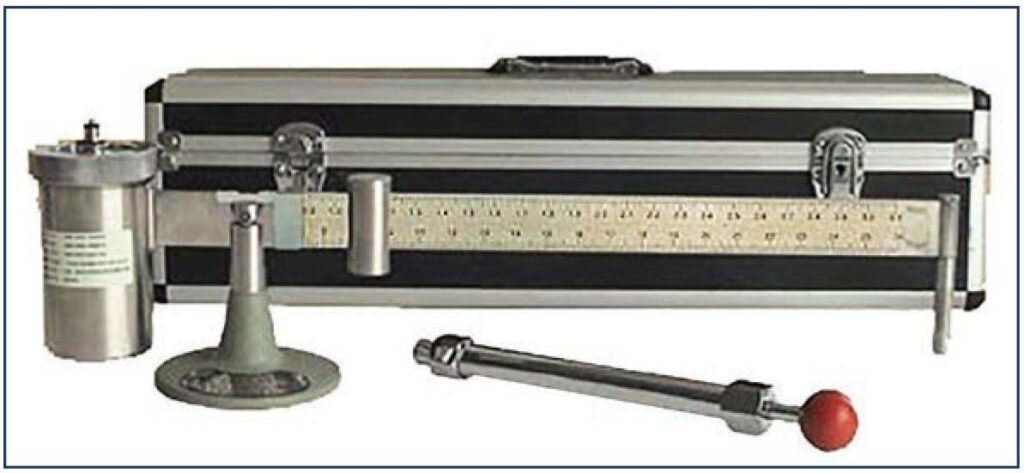
- Ensure that the pressurized mud balance that will be used to check the slurry density during the cement job has been calibrated. The densitometer on the cement unit (if fitted) must also be calibrated.
- Check the condition of the rig mud pump. One pump is often serviced as a matter of course prior to a cement job to minimize the chance of a complete failure while displacing cement. The volumetric efficiency of the mud pumps should also be checked (e.g. by pumping from one tank into another or other forms of calibration) to ensure that the correct number of strokes is calculated for the displacement volume (Cementing Calculations).
- The cement unit and lines should be pressure tested. The pressure test value should exceed the anticipated maximum operating pressure during the job by a reasonable margin. The accuracy of liquid additive system screw pumps should be checked
Cement Placement After Drilling Tips & Techniques
Choosing a cement placement technique is mandatory to be applicable to your requirements. There are several techniques that are discussed in detail in the cementing placement techniques and method article. The major placement techniques are as follows:
- Single Stage Cement Jobs
- Stinger Cementing
- Multiple Stage Cementing
- Liner Cementing Placement
- Outside Cementing (Top Fill)
- Setting Cement Plugs
- Squeeze Cementing
Surface Cementing Equipment
Cement Transport, Handling, and Storage Equipment
Dry cement is usually transported from the supplier or Service Company directly to the well site by road, rail, or on a supply boat, for offshore operations. On-site the cement is stored either in bulk silos (most common), big bags or sacks (not very common).
Silos are fitted with nozzles for blowing air to ‘fluidize’ the dry material and some arrangements to gauge the contents, for example, a load cell. For dry blending operations, a ‘weighing’ silo of small capacity mounted on a weighing device is required.
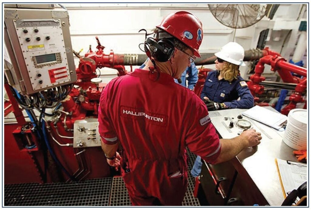
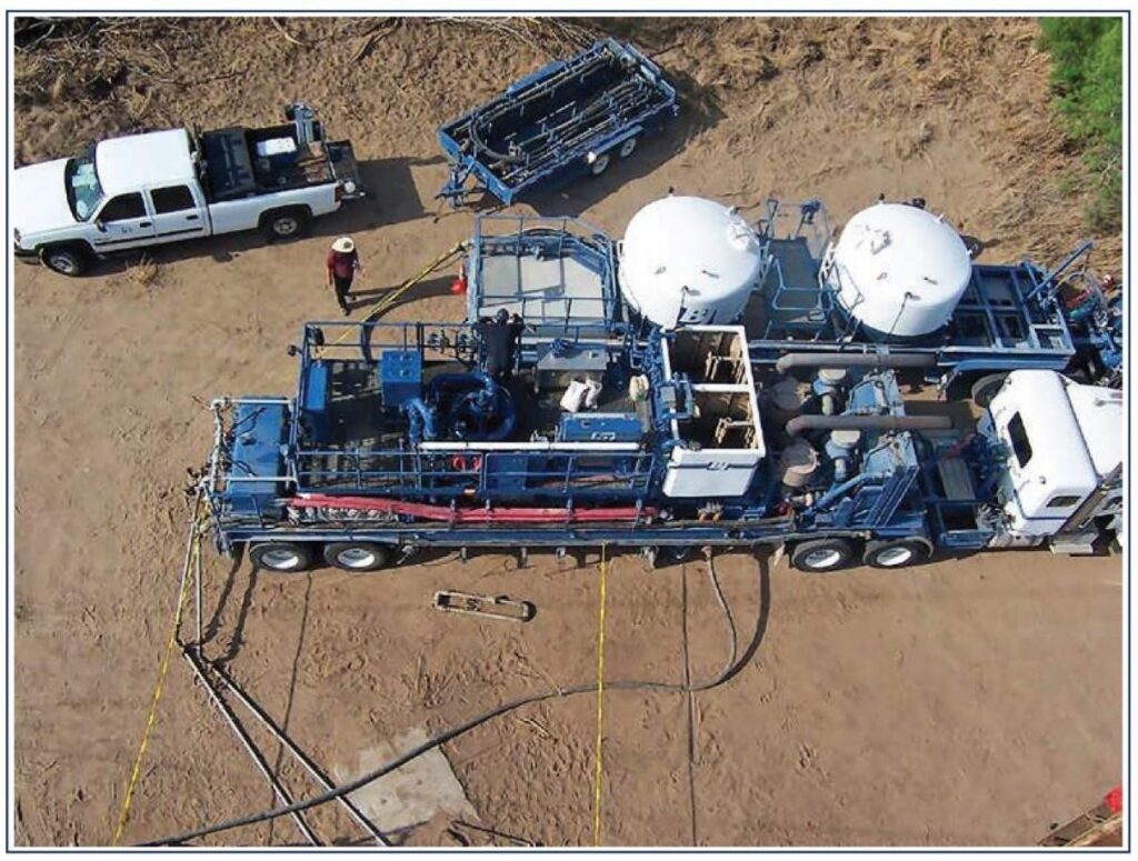
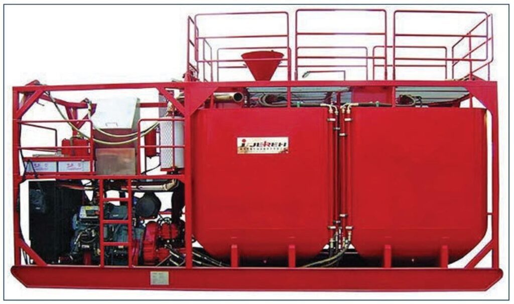
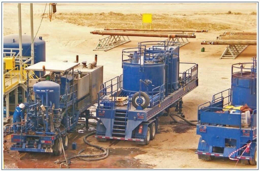
Mixing and Pumping Equipment
The slurry is mixed by blending cement with mix water in a cementing unit. This can be a (semi-) permanent installed facility on offshore rigs (Types of drilling rigs) or a mobile one mobilized for the job.
Jet mixing
The simplest cementing system is the jet mixer. Dry cement is fed from a hopper into a bowl fitted with one or more jet nozzles through which the mix water is pumped at high velocity, creating a venturi effect drawing in the powder. The mixture is discharged into a tub, which serves as suction for the high-pressure cement pumps. The slurry density is adjusted by altering the water/cement ratio through a by-pass over the nozzles which reduces the venturi effect.
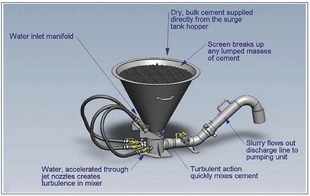
Jet mixers are heavily dependent on the expertise of the operator and rarely deliver a consistent slurry density – especially at the start of the mixing operation.
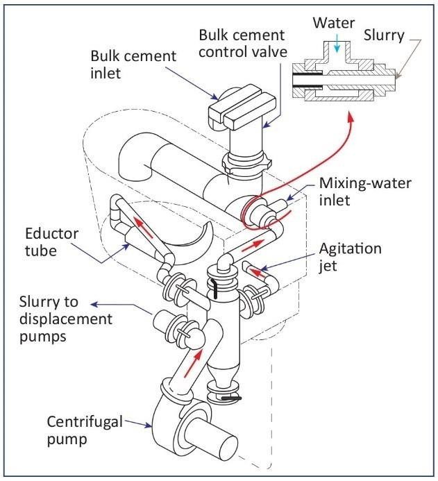
Re-circulation mixing
With a recirculating mixer, part of the slurry is re-circulated from the slurry tub back through the jet nozzles. This creates more shearing and allows for tighter control of the density before it is pumped downhole
Re-circulation mixers are now often computer-controlled and provide high mixing energy with constant consistent slurry density at high pump rates.
Batch mixing
Batch mixing has the slurry prepared using either a jet or recirculation mixer but then pumped to a storage tank. The tank has paddle mixers or jets to keep the slurry moving and ensure a consistent slurry quality.
Batch mixing is preferred for critical cementations such as liner cement jobs or balanced/kick-off cement plugs, as the whole slurry volume can be guaranteed to be of the correct density before any is pumped. There is a limitation in the cement volume (i.e. the size of the batch tanks) that can be used this way.
Cement Pumps
A cementing unit is principally a pumping platform that is also used to control the mixing and pumping process. Depending on location, the cement unit will provide power to a range of cement pumps from diesel engines or electric motors. Power can bear direct drive or via hydraulic pumps. Various pumps are used to move slurry between stages, including:
- Centrifugal pump(s) for re-circulation mixing and mix water transfer
- High-pressure displacement and mixing pumps.
Temporary Pipework
The cement slurry is usually pumped to the casing cementing head through a temporary connection made up with chiksans, which shall always be fitted with safety slings. The chiksans are usually fitted with Figure 1502 hammer unions. In some operations, a permanent line is installed to connect the cementing unit with the stand-pipe manifold on the drill floor. The connection to the cementing head is made through a short length of high-pressure hose or made up of chiksan joints. All 1502 hammer unions shall have welded connections.
Cementing Head
Cement is pumped into the top of the casing via the cement head. It will usually contain one or more cementing plugs. Heads capable of storing multiple plugs are preferred over those just carrying single plugs. A plug will usually be pumped immediately ahead (bottom plug) and behind (top plug) the cement.
Cementing Plugs
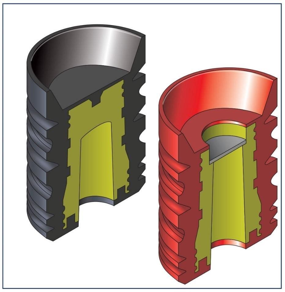
Cementing plugs prevent contamination of cement slurry with the drilling fluid as the slurry is pumped down the casing. They are made of moulded rubber, usually with an aluminum, plastic, or composite material core. Plugs need to fit tightly in the casing and are designed for a limited range of casing weights/sizes.
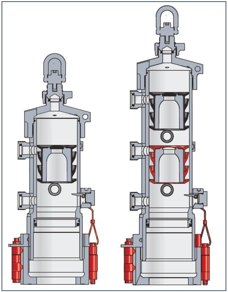
The bottom plug has a thin diaphragm or membrane that shears open when the plug lands on the float equipment. The top plug is solid and allows the casing to be pressure tested at the end of the cement job.
The Evaluation of Cementing Operations
The position of the top of cement can be established in three ways:
- By temperature survey.
- By the pressure differential method.
- By Electronic logging
In addition to locating the position of TOC, it is mandatory to make sure that the cement bond is good, especially for the production casing.
Read more on Cement Evaluation Article
Cement Types and Additives
Given the wide variation in well conditions that can be experienced, the properties of neat Portland cement may not always be suitable for a specific job. For example, the well may be very hot or have high pressure, or a longer or shorter thickening time may be required. To ensure the cement slurry is competent for the expected well conditions additives are used to modify the cement properties. They are added to perform different functions:
- Density Control
- Dispersants or Friction Reducers
- Cement Accelerators
- Cement Retarders
- Fluid Loss Control
- Lost Circulation Material
- Specialty Additives
Historically, cement was supplied to the wellsite in 1 ft3 (0.028 m3) sacks. Due to the bulk density of dry Portland cement, these weighed 94 lbs (42.6 kg) per sack. Cement slurries are described in terms of yield and mix water content. Nowadays, the yield may also be expressed as m3/MT
Yield specifies how many cubic feet of cement will be created per 94lb sack of dry cement powder when mixed with the mix-water. The mix-water requirement is expressed in gallons per 94lb sack of dry cement powder.
When Cement additives are included in cement slurry designs the proportions that can be added they are quoted in a variety of ways:
- % BWOC – By Weight of Cement: This is a % expressed in terms of the weight of the dry cement powder.
- % BWOW – By Weight of Water: this a % expressed in terms of the weight of mix-water used to blend the slurry
- Lbs/sx – pounds per sack: The additive is added in proportion to the dry weight of cement used to create the slurry.