A centrifugal mud pump should be selected for the duty it must perform: the required flow, the head needed to move that flow through the circuit, and the suction conditions available at the pump. A large motor or familiar flange size cannot establish those three things. The same pump can behave differently when its piping, impeller, speed or drilling fluid changes. [1, pp. 470–471, 479–488]
This article concerns surface centrifugal pumps used for transfer, mixing and equipment feed. It separates their selection problem from the high-pressure reciprocating equipment covered in the mud-pump parts and calculations guide. The objective is to prepare a defensible duty description and interpret performance evidence, without turning a general article into a pump operating procedure.
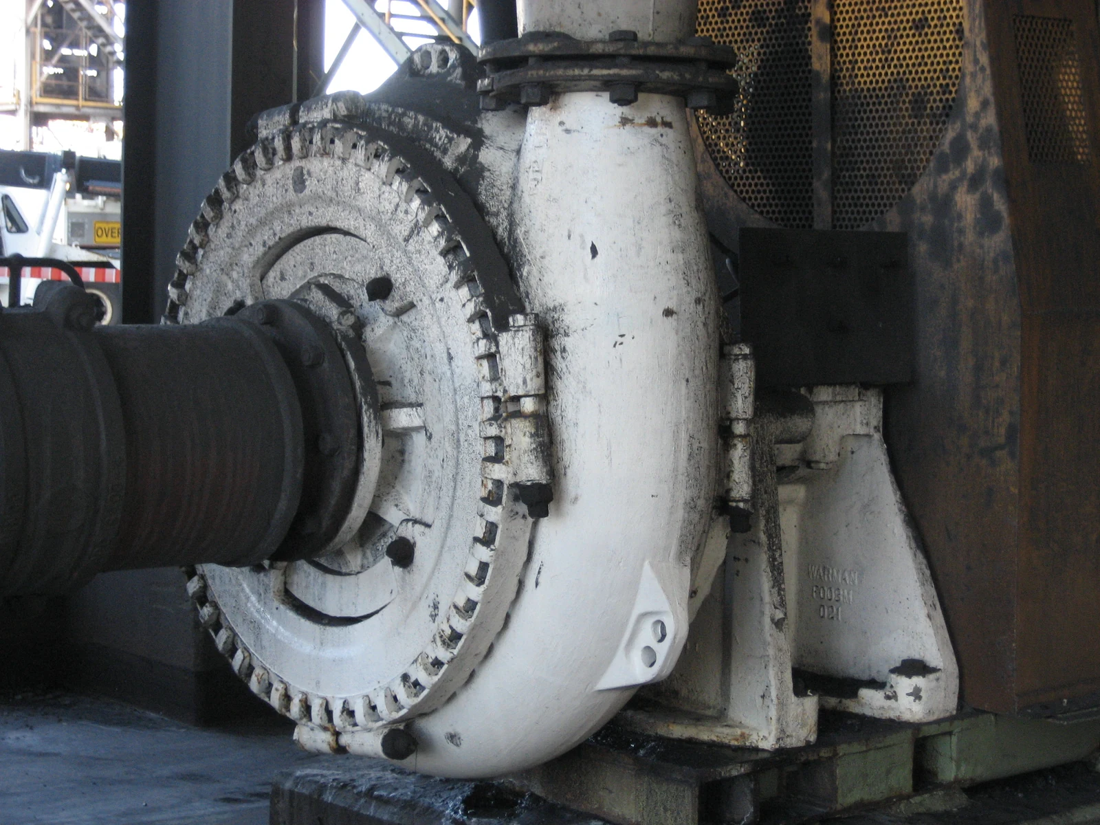

Start with the centrifugal mud pump duty
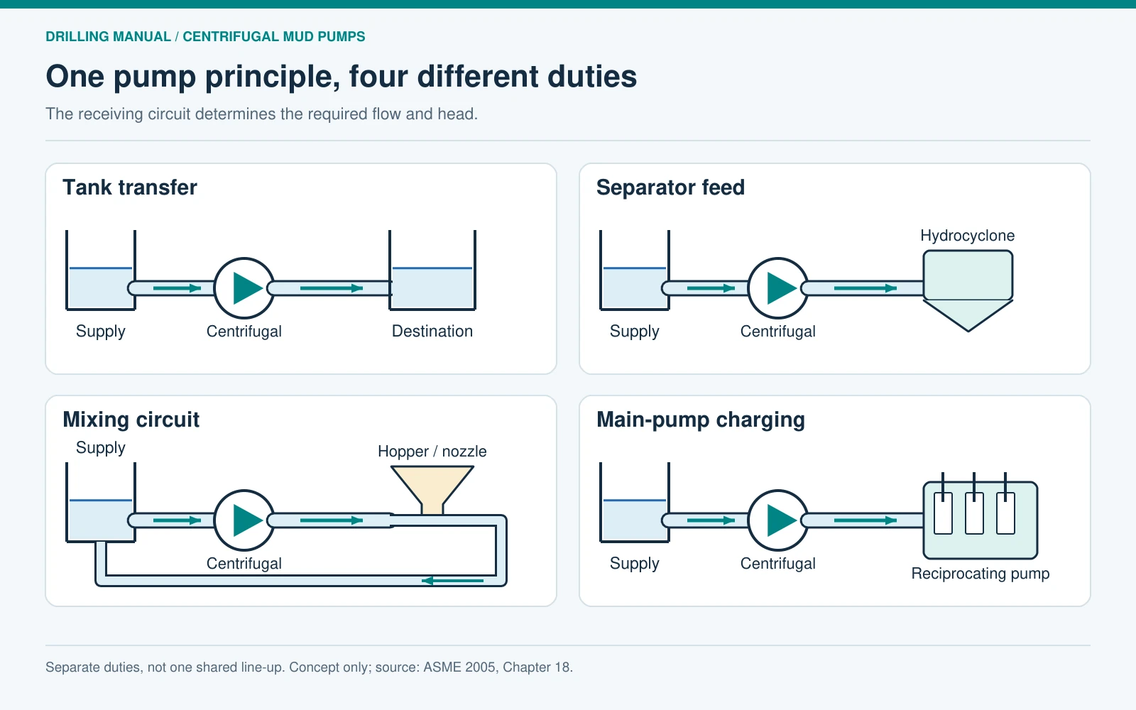
Several surface duties can use the same broad pump principle, but they impose different hydraulic demands. Transferring mud between tanks involves the connecting route and destination. Feeding a hydrocyclone also requires the appropriate inlet conditions at that device. A mixing circuit must account for its nozzle and return route. A charging pump supplying a reciprocating mud pump has a further complication: the receiving pump draws fluid in strokes. The ASME handbook treats that last application separately. [1, pp. 470–471, 479–488, 510–511]
| Duty | Question to resolve | Related equipment boundary |
|---|---|---|
| Tank transfer | What flow is needed through the actual route and elevation difference? | The transfer destination sets part of the required head. |
| Hydrocyclone feed | What flow and inlet head does the selected unit require? | The centrifugal pump supplies the separator; it does not perform the separation. |
| Mud mixing | What does the complete mixing circuit require? | The hopper and nozzle are part of the hydraulic load. |
| Main mud-pump charging | Can the supply arrangement meet the receiving pump’s changing suction demand? | Charging duty does not replace the reciprocating pump’s pressure-generating function. |
Use the mud mixing hopper guide for the mixing mechanism and the desander and desilter guide for the separator itself. A centrifugal mud pump assessment should begin with the requirements of whichever circuit it actually serves.
How the impeller and casing move mud
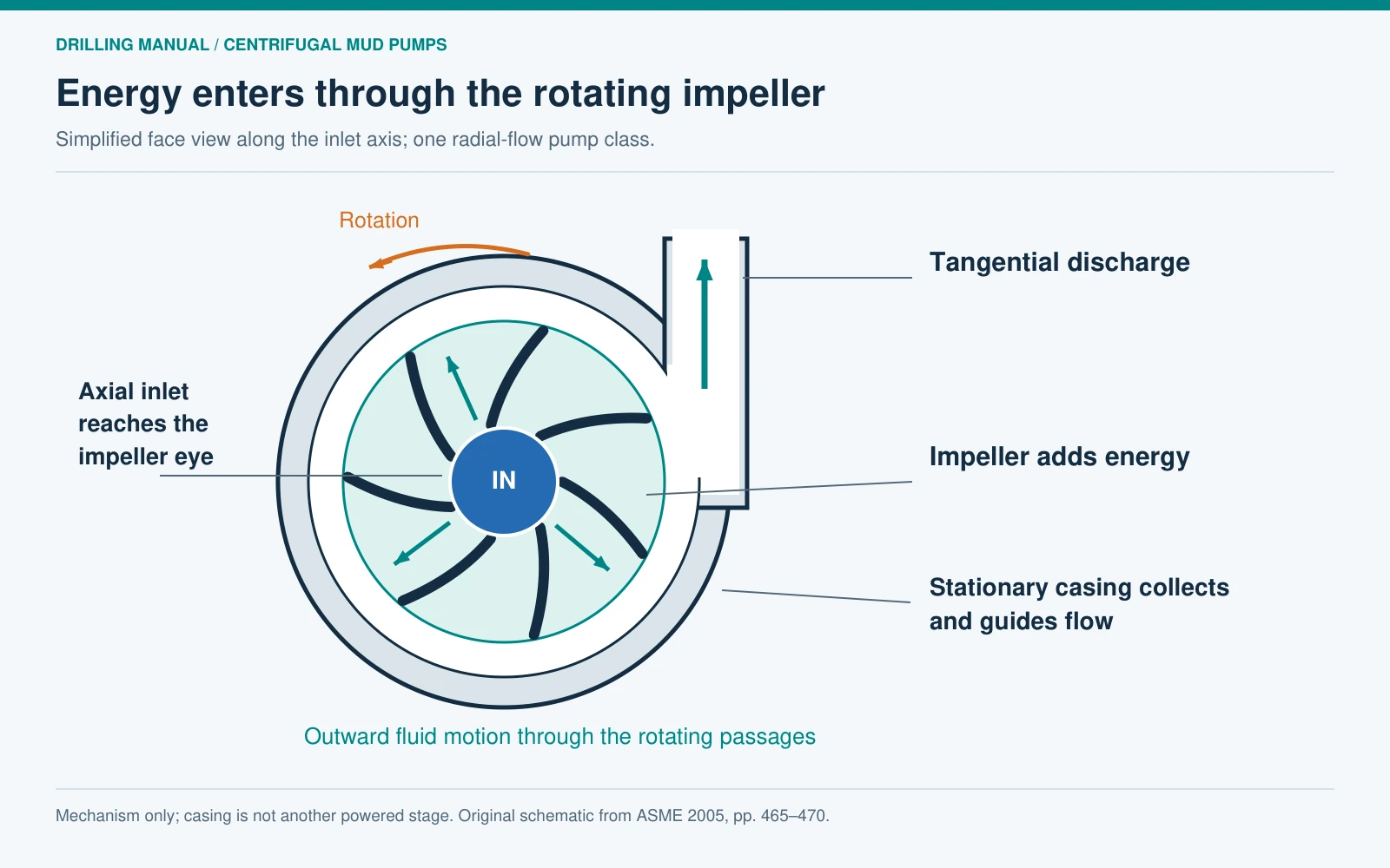
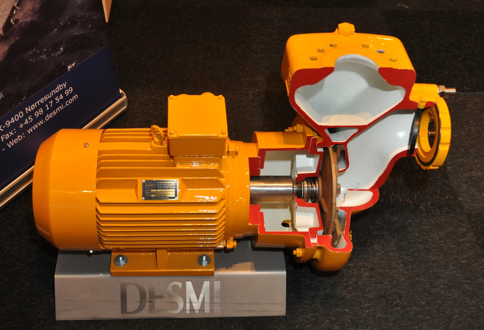
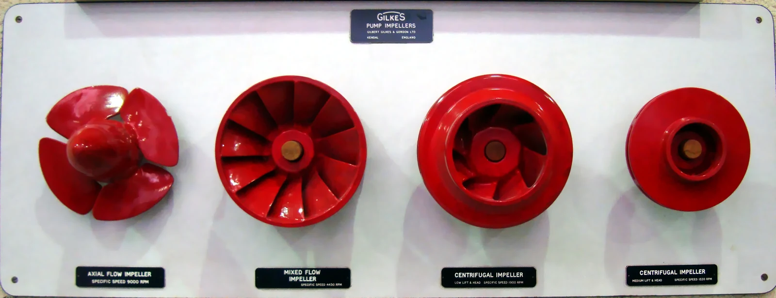
The radial-flow arrangement discussed here receives liquid near the impeller eye. Rotation transfers energy to the liquid as it moves outward through the impeller passages. The casing directs the inlet flow, collects the impeller discharge and guides it toward the outlet. A tangential-discharge casing therefore belongs in the flow drawing; the suction connection should not be shown feeding the impeller rim. [1, pp. 465–468]
The impeller supplies the energy. The stationary casing manages the flow and pressure recovery, with hydraulic losses; it is not an additional powered stage. Open, semi-open and closed impellers also have different arrangements of rotating and stationary surfaces. A simplified illustration explains the principle, not the internal geometry of every centrifugal mud pump. [1, pp. 466–470]
Clearances matter because fluid can recirculate internally from the higher-pressure region toward the inlet. Wear can increase that leakage and reduce useful performance. That gives a reason to compare an installed unit with its correct performance information, rather than assuming that its nameplate identifies the flow it is currently delivering. [1, pp. 468–470]
Read the centrifugal mud pump curve
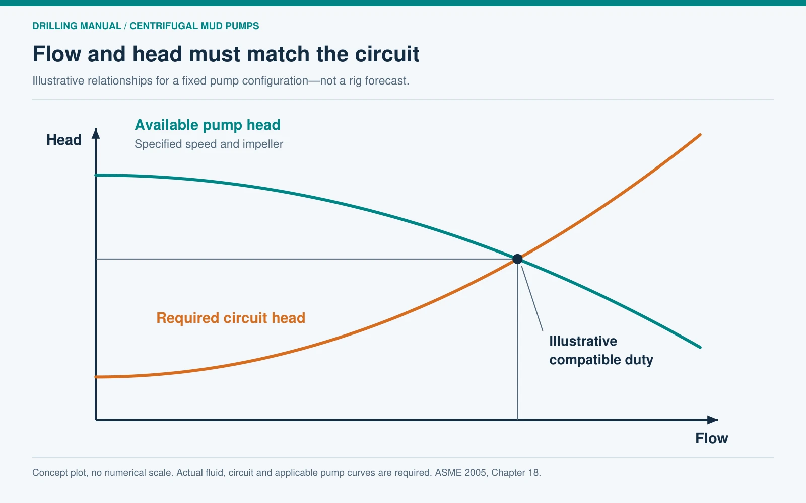
Flow is the volume moved per unit time. Head expresses hydraulic energy per unit weight of liquid and is commonly presented as feet or metres of that liquid. The pump must add enough head to overcome the relevant elevation, piping losses and delivery requirement after allowing for the conditions already present at its inlet. Consequently, a discharge pressure reading alone does not establish the pump’s added total head. [1, pp. 470–471, 479–482]
A centrifugal mud pump curve is tied to a specified configuration. Check the impeller diameter and rotational speed before using the head-flow curve, efficiency information, power curve or required suction-head curve. A centrifugal mud pump curve for another configuration can answer the wrong question with apparently precise numbers. The practical duty is where the pump’s available head and the circuit’s required head are compatible at the same flow. The accompanying sketch illustrates that relationship without predicting a particular rig’s operating point. [1, pp. 479–488]
Changes to the circuit can change the operating flow even when the pump and motor remain in place. Equally, changing speed or impeller size changes the pump relationship. The book discusses affinity relationships, but a water-based rule of thumb is not a substitute for evaluating the actual drilling fluid and equipment. A drilling-mud system curve should not be invented by applying a simple water-friction expression to every rheology. [1, pp. 467, 479–488, 505–508]
Same head, different mud density: pressure and power
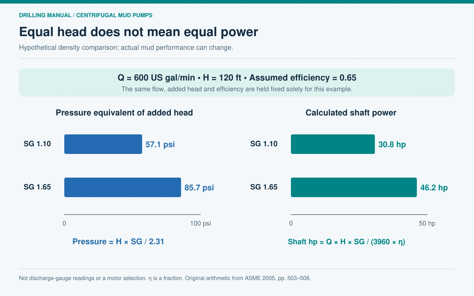
Head, pressure difference and shaft power are connected, but they are not interchangeable. The following original calculation isolates density. Assume two hypothetical liquids are delivered at 600 US gal/min with 120 ft of added head and an assumed pump efficiency of 65%. Their specific gravities are 1.10 and 1.65. Hold flow, head and efficiency fixed solely for this comparison. [1, pp. 503–508]
In these units, pressure equivalent to the added head is H × SG ÷ 2.31. Required shaft horsepower is Q × H × SG ÷ (3960 × efficiency), with efficiency entered as a fraction. These are the handbook relationships applied to invented inputs. [1, pp. 503–508]
| Quantity | Case A | Case B |
|---|---|---|
| Specific gravity | 1.10 | 1.65 |
| Assumed flow | 600 US gal/min | 600 US gal/min |
| Assumed added head | 120 ft | 120 ft |
| Assumed pump efficiency | 65% | 65% |
| Pressure equivalent of added head | 57.1 psi | 85.7 psi |
| Calculated shaft power | 30.8 hp | 46.2 hp |
The denser case requires 50% more shaft power under these assumptions, although the added head is unchanged. The pressure figures are not predicted discharge-gauge readings: inlet conditions and the measurement locations still matter. Shaft power is also not electrical input power or a selected motor rating.
For a centrifugal mud pump, actual fluids can differ in viscosity and solids as well as density, changing efficiency and hydraulic performance. The calculation therefore does not promise that an unchanged centrifugal mud pump will maintain this flow after a mud-property change. It explains why density belongs in the duty specification and why a water-based horsepower curve needs interpretation. [1, pp. 467, 483–488, 503–508]
Check the suction conditions separately
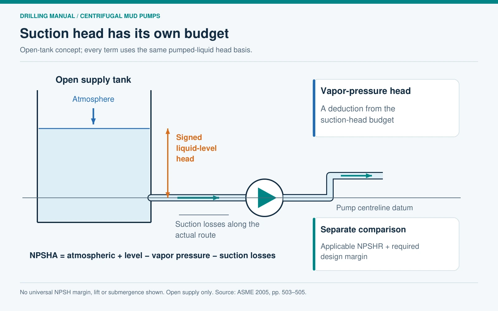
A centrifugal mud pump can have enough discharge capability and still have an inadequate suction arrangement. Net positive suction head available, NPSHA, expresses the inlet head available above the liquid’s vapor-pressure head. Net positive suction head required, NPSHR, is associated with the selected pump and its operating flow. They answer a different question from the total head needed by the discharge circuit. [1, pp. 485–488, 503–505]
For an open supply tank, the conceptual NPSHA budget includes atmospheric pressure head and the signed liquid-level head, less vapor-pressure head and suction-line losses. Every term must use a consistent fluid-head basis and datum. The lowest relevant liquid level, operating temperature and actual suction route matter; a favorable tank level observed once does not describe every operating condition. [1, pp. 503–505]
The comparison must use the applicable pump curve and the margin required by the equipment and project design. This article deliberately supplies no universal margin, suction lift or minimum submergence. Those depend on the installation and fluid. It also does not extend the open-tank expression unchanged to a different supply-pressure arrangement.

Cavitation and entrained air are different problems
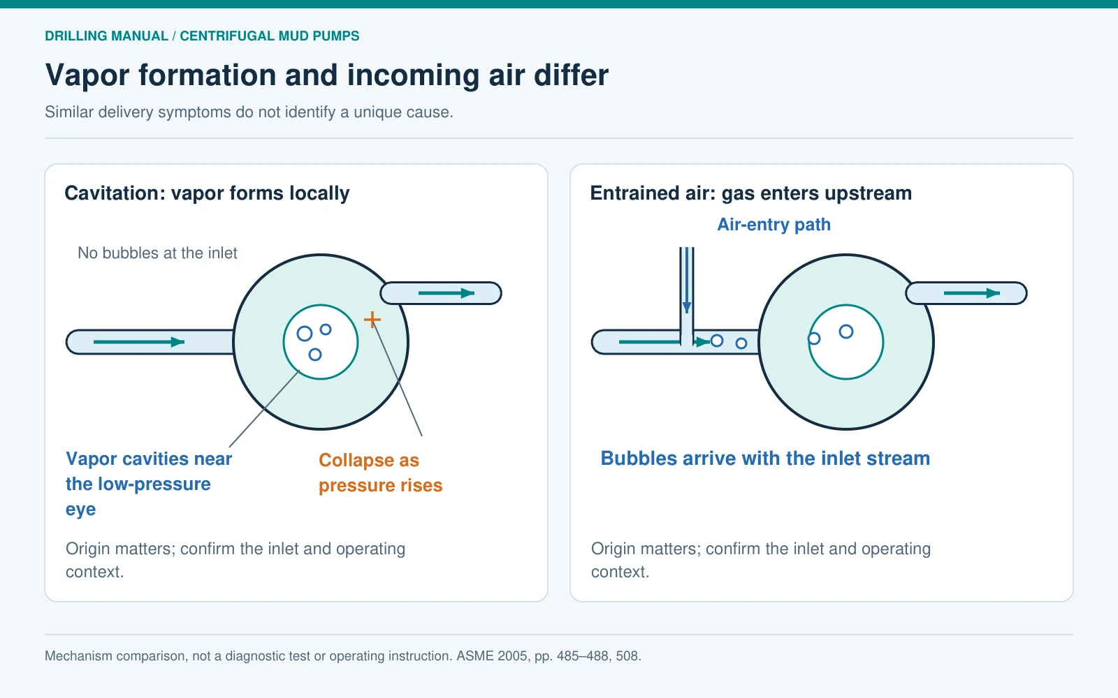
Cavitation begins when local pressure becomes low enough for liquid to form vapor cavities. As those cavities reach a higher-pressure region, their collapse can damage surfaces. In contrast, entrained air enters with the fluid or through an air-entry path; it did not originate simply because the pumped liquid vaporized at the impeller eye. The handbook identifies suction leakage and surface vortices among possible air-entry mechanisms. [1, pp. 485–488, 508]
Both can interfere with delivery, so noise or an unstable flow indication is not a unique diagnosis. A centrifugal mud pump investigation needs the suction-pressure and supply-level context, fluid temperature, evidence of gas entry, and the actual operating point. More motor power does not establish that the inlet conditions are adequate.
The centrifugal mud pump arrangement in this discussion also relies on an established liquid path; it should not be assumed to be self-priming. Priming provision, air handling and the applicable equipment instructions are design questions, rather than details to infer from the motor size or outlet pressure. [1, pp. 485–488]
Use symptoms to select evidence, not a single diagnosis
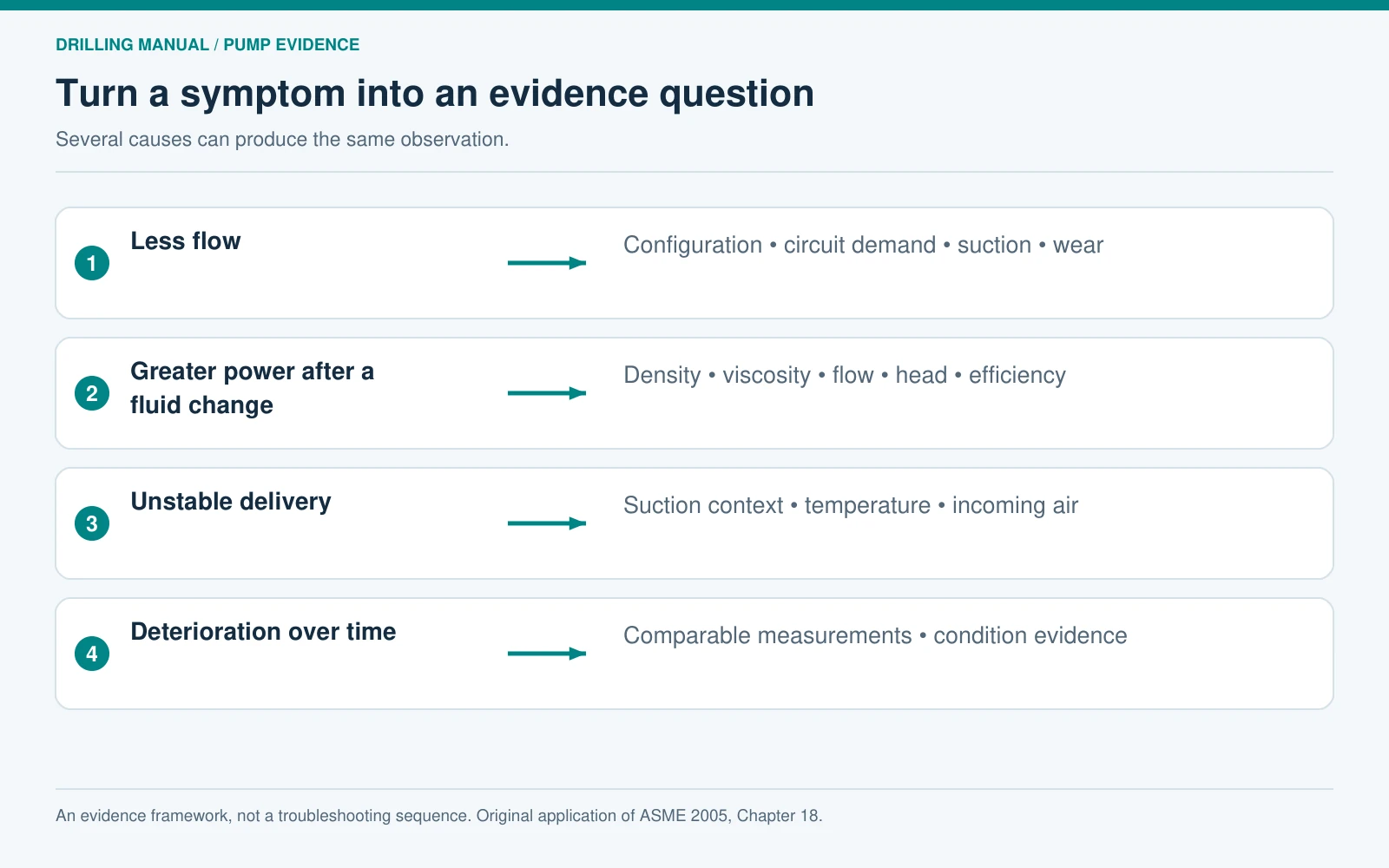
The following review table applies the handbook’s hydraulic and mechanical relationships. It is an evidence checklist, not a troubleshooting sequence or an instruction to alter a running system. Several causes can produce similar symptoms. [1, pp. 468–471, 479–488, 503–508]
| Observation | Evidence worth comparing | What the observation cannot establish alone |
|---|---|---|
| Less flow than expected | Actual speed and impeller, full circuit requirement, inlet conditions and wear evidence | That the motor is too small |
| More power required after a fluid change | Density, viscosity, flow, head and efficiency assumptions | That density is the only changed variable |
| Noise with erratic delivery | Suction-head assessment, supply level, temperature and air-entry evidence | Whether the cause is vapor formation or incoming gas |
| Delivery deterioration over time | Repeatable duty measurements and condition information for wetted parts | That internal wear is the only possible cause |
Keep the pump review connected to its process. For example, inadequate feed to a separator and a fault inside that separator require different evidence. The solids-control equipment overview helps locate the receiving equipment, while the mud-system inspection guide addresses the broader installation.
Prepare a useful centrifugal mud pump selection brief
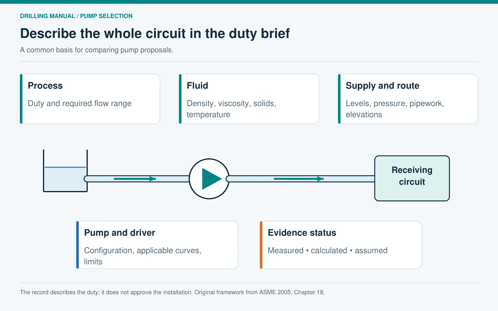
A centrifugal mud pump selection request should describe the required duty and its range, not just request a nominal pump size. The ASME selection discussion starts with fluid properties and the physical circuit, then relates them to head, flow and the driver. [1, pp. 470–471, 479–488, 503–505]
- Process: identify transfer, mixing, separator feed or charging service, with the required flow range and destination requirement.
- Fluid: identify the drilling-fluid system and relevant density, viscosity, solids and temperature conditions.
- Circuit: provide the inlet supply conditions, liquid-level range, elevations, pipe sizes, route and restrictions.
- Equipment: identify the proposed or installed pump, impeller, speed, applicable curves and driver limitations.
- Evidence: distinguish calculated requirements, measured conditions and assumptions that still require confirmation.
That record makes different proposals comparable. It also makes later changes visible: an altered route, a different mud or a new receiving device may change the duty without changing the pump’s nameplate. A defensible centrifugal mud pump decision connects all three: what the process needs, what the pump can supply, and what the inlet can support.

Frequently asked questions
Is a centrifugal mud pump the same as a triplex mud pump?
No. The centrifugal pump adds energy through a rotating impeller. A triplex pump displaces fluid with reciprocating pistons. A centrifugal unit may supply the triplex suction, but the receiving pump’s stroke demand makes that a distinct charging duty. [1, pp. 465–468, 510–511]
Does a larger motor guarantee more flow?
No. The hydraulic configuration and circuit determine the compatible head and flow. Additional available motor power does not, by itself, change impeller geometry, speed, suction conditions or the system requirement. Evaluate those together. [1, pp. 479–488, 503–508]
Does equal head mean equal pressure for different mud densities?
No. Pressure equivalent to a specified head rises with specific gravity. In the hypothetical comparison above, 120 ft corresponds to 57.1 psi at SG 1.10 and 85.7 psi at SG 1.65. Those are head equivalents, not standalone discharge readings. [1, pp. 503–508]
Can a water performance curve be used without correction?
It is useful starting information, but it does not settle drilling-fluid performance. Density affects the pressure and power interpretation, while viscosity can alter performance and efficiency. Use the actual fluid conditions and the applicable equipment evaluation. [1, pp. 467, 483–488]
Does cavitation always mean air is entering the suction?
No. Cavitation concerns vapor cavities formed from the liquid at low local pressure. Air can arrive from a separate entry path. Similar delivery symptoms do not make their causes identical. [1, pp. 485–488]
What should be known before comparing pump quotations?
Establish the service, flow range, required head, fluid properties and suction arrangement. Then compare the proposed pump configuration, curves and power requirements on that common basis. A flange designation alone is not a complete duty specification. [1, pp. 470–471, 479–488]
References
- Lee, Todd H. ‘Centrifugal Pumps,’ Chapter 18 in Drilling Fluids Processing Handbook. ASME Petroleum Division-sponsored handbook. Gulf Professional Publishing / Elsevier, 2005. ISBN 0-7506-7775-9. Printed pages: 465–471, 479–488, 503–508, 510–511. PDF pages in the edition consulted: 492–498, 506–515, 530–535, 537–538.