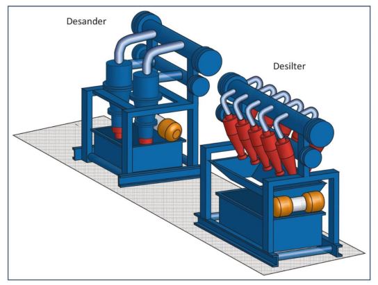
Desanders and desilters (Figure 1) are secondary solids control equipment used in oil and gas drilling rigs (check also: types of drilling rigs) that use hydrocyclones. They operate using the centrifugal force created by injecting fluid tangentially at high speed, these exaggerate the differences in settling speed of different size particles of the same density.
This allows the different size particles to be separated from each other. In particular sand, silt and clay can be separated. The denser/larger material is driven outward towards the conical wall and downward into an accelerating spiral (conservation of angular momentum) along the wall to the discharge point at the apex of the cone. The lighter-phase material moves inwardly and upwardly as a spiraling vortex to the light-phase discharge connection of the cyclone.
Desanders & Desilters Design In Oil And Gas
Geometry, the design and positioning of various connections, and their relative dimensions are critical for efficient cyclone operation and determine the cut-off point (between the solids ejected from the apex and those remaining in the liquid discharge).
The size of the particles by desanders and desilters that can be separated depends on:
- Size of the cyclone.
- Split ratio underflow/overflow.
- Inlet header pressure.
- The efficiency of the cyclones depends on the following factors:
- The cyclone design
- The rheological properties of the fluid
- The range of sizes of the solids to be removed
- Operating pressure
Application
Hydrocyclones of desanders and desilters in drilling are used to remove sand and silt particles from the drilling fluid that has already passed the oil and gas shale shaker. Their advantages are that they:
- Remove fine drill solids
- Are relatively simple in design
- Have no moving parts
- Are easy to operate
- Have a large capacity
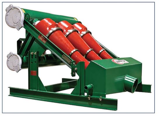
6″ to 12″ hydrocyclones are used to remove sand. The cyclones are arranged in batteries, fed by a centrifugal pump. Figure 2 shows a desander. The heavy discharge from the bottom of the unit is discarded while the cleaned mud leaves from the top of the cyclone and is discharged into the next tank
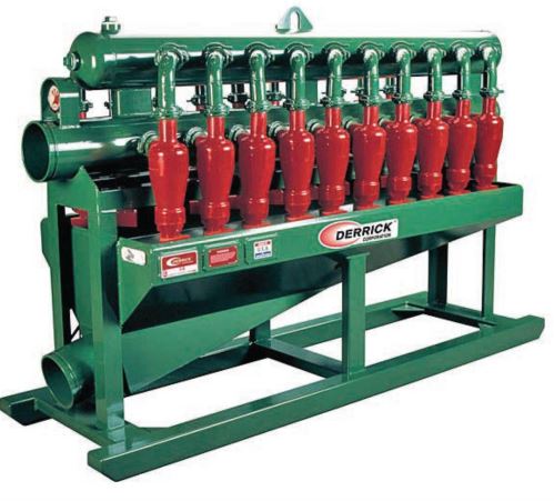
Finer silt is removed using 2-4″ cyclones. The smaller size of these units creates faster movement and thus greater force. However, the throughput of each unit is less and so, to permit treatment of the full mudflow, a larger number of units must be mounted together (Figure 3).
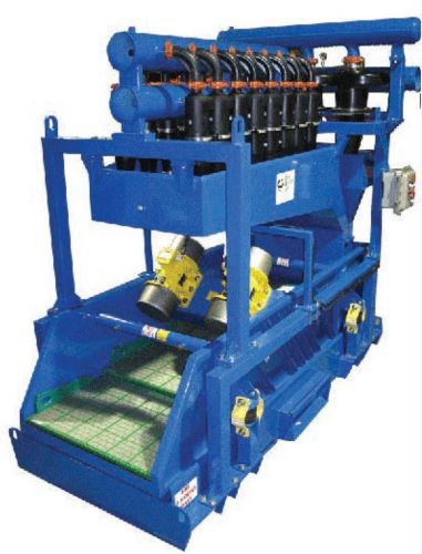
With oil-based fluids, desanders and desilters alone are generally inefficient in oil and gas wells. The liquid lost via the underflow has often resulted in pollution and disposal problems. Under these circumstances, a mud cleaner (Figure 4) can help to remove drilled solids. The discharge falls onto a shaker screen and can be dried, recovering much of the entrained mud. The liquid can either be returned to the mainstream or passed through a centrifuge if necessary. The oil is then saved and the material to be disposed of is in dry form.
Mud cleaners are very inefficient and the need for their use has been replaced by the advent of linear motion shakers (check also: Shale Shaker Design & Performance) combined with the use of centrifuges.
Performance
The performance characteristics of hydrocyclone cones are shown in Table 1.
Experience in oil and gas shows that the best desanders (150 mm or 6″) will remove almost 100% of particles greater than 74 μm and the best desilters 100% of particles greater than 50 μm. The median cut of these units would be > 30 μm for desanders and > 15 μm for desilters.
Barites particles (check also: Barite in Drilling), because of the higher SG. (4.2) and hence higher equivalent spherical diameter ratio (1.5) will always be removed more effectively than sand and silt. For this reason, hydrocyclones can only be used for the desanding and desilting of unweighted drilling fluids. If the fluid is weighted with barites there will be excessive loss of valuable densifying material (check also: WBM Chemicals – OBM Chemicals).
| of cyclone (inches) | Removal of … | Removes low s.g. (= 2.6) particles down to (microns) |
| 12 | Sand | 74 |
| 8 – 6 | Sand & silt | 40 |
| 4 – 3 | Silt | 15 |
| 2 | Silt | 5 |
The smaller the diameter of the cyclone, the higher is the operating pressure and the smaller the particles that can be removed.
The practical pressure operating range for oil and gas hydrocyclones is 200-350 kPa (30-50 psi) with the smaller desilters running at a higher pressure than the desanders. Too low a pressure results in inefficient separation; too high a pressure will give a better separation but the bladders will fail.
The Underflow In Oil And Gas Desanders & Desilters
The underflow from a cyclone should look like a spray (Figure 5). This indicates that the cones are operating at maximum efficiency. A rope-type discharge indicates the cyclone is overloaded; separation will be inefficient and rig mud pump wear will be excessive. The aperture in the apex must be adjusted by opening it further.
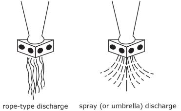
Once the correct “spray” discharge is obtained the amount of underflow can also be regulated by opening/closing the apex. An underflow rate of some 3 % of throughput is required to avoid bottom plugging. Another reason for a minimum of 3 % underflow is that, at lower rates, the size of particles that will be removed is unfavorably affected, as too much solid will remain in the fluid.
| Symptom | Possible cause |
| No discharge at the apex | 1- Bottom apex opening plugged 2- Inlet orifice completely plugged 3- Bladder cut out and plugging discharge 4- Feeder header full of trash |
| Flooding liquid out of apex (roping) | 1- Pump pressure too low 2- Inlet orifice partially or completely plugged 3- Bladder cut out 4- Inlet orifice of liner improperly installed 5- Feeder header full of trash |
| Inlet-header pressure fluctuating | Air, gas or foam in drilling fluid at pump suction |
The Installation of Desanders and Desilters
When treating the drilling fluid to remove a specific size range 100% of the fluid stream must be processed, because particles not removed the first time are circulated back down the hole again. Not only do they then increase the erosion of the drill string, Bottom Hole Assembly, and open hole, they themselves are subject to abrasion and regrinding under the oilfield drilling bit. The particles may then become too fine to be easily removed on their return to the surface. A build-up of solids in the drilling fluid results that cause hole cleaning problems.
Given that the complete fluid stream must be processed the hydrocyclone capacity for each treatment should be in excess of the maximum pump volume of the rig pumps. And since the size, and thus capacity, of the hydrocyclone is in practice fixed by the size of particle it is designed to remove, the only way to achieve the required processing capacity is to increase the number of units working in parallel. A 6″ cone can process approximately 380 l/ min (2.5 bbls/min) and a 4″ cone 190 l/min (11.25 bbls/min).
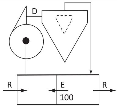
An oil and gas desander is fed by a centrifugal pump the pump mud has a capacity at least 1.25 times the planned circulating rate (e.g. 1250gpm if circulating around the well at 1000gpm) . Drilling fluid should flow out of the top of the sand traps into a small suction pit. The centrifugal pump sucks out of this tank. The underflow from the top of the desanders is discharged into the tank downstream. These two tanks should be connected by an equalizing valve at the bottom of the tanks.
Because the centrifugal pump is faster than the rig pumps there will always be a flow of mud from the discharge pit into the suction pit. This way 100% of the flow will be treated. This system is shown in Figure 6
When both oil and gas desanders & desilters are running, the hookup should be as shown in Figure 7. Again, both centrifugal pumps should be 125% of the rig pump rate. All three tanks should be connected at the bottom by equalizing valve. Fluid should overflow out of the last tank into the rest of the tank system.
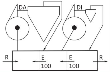
These designs mean that there is no need to switch off the solids control equipment when the mud pumps are stopped.
Problems with Hydrocyclones
The following problems may be encountered when using desanders hydrocyclone;
- The centrifugal pump and cyclone operate with entrapped air; this is sometimes caused by air being sucked in via vortexes in the suction tank if its level is low; the suction tank requires at least a 1.5 m (5 ft) fluid column above the suction of the pump.
- The apexes become plugged with solids, chemicals, etc.; this can usually be avoided with screens on the centrifugal pump suction.
- Uneven feed distribution in multi-cone sets.
- Irregular operation due to faulty manifolding; each cyclone unit should have its own pump and, for example, not be part of the hopper system; each pump should be dedicated to only one task.