Gas lift in oil wells uses compressed gas to help reservoir fluids reach the surface. In a conventional tubing-flow completion, gas travels down the space between casing and tubing, crosses into the tubing through a valve, and returns with the produced fluids. The entry point is therefore in the wellbore. Reservoir pressure maintenance, in contrast, injects into the formation. [1], [2]
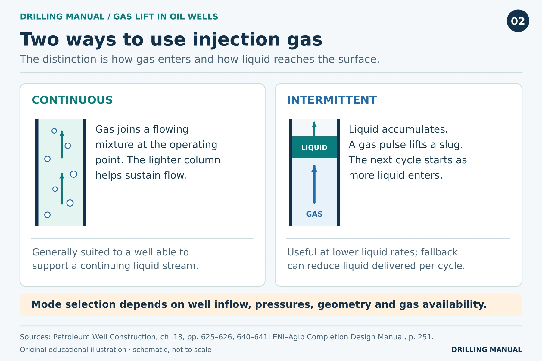
There are two principal operating modes. Continuous lift feeds gas into a flowing stream to reduce the hydrostatic pressure the reservoir must overcome. Intermittent lift allows liquid to collect, then admits gas beneath it to lift a slug. Both the reservoir’s refill rate and the available injection gas influence that choice. [1], [2]
How Does Gas Lift Work in an Oil Well?
Follow the gas from the compressor. Compression raises its pressure so that it can enter the well through the tubing–casing annulus. Meanwhile, the tubing carries reservoir fluids and returning lift gas to the separator. Some separated gas can return to the compressor; another source may be needed if the available volume is insufficient. [1], [2]
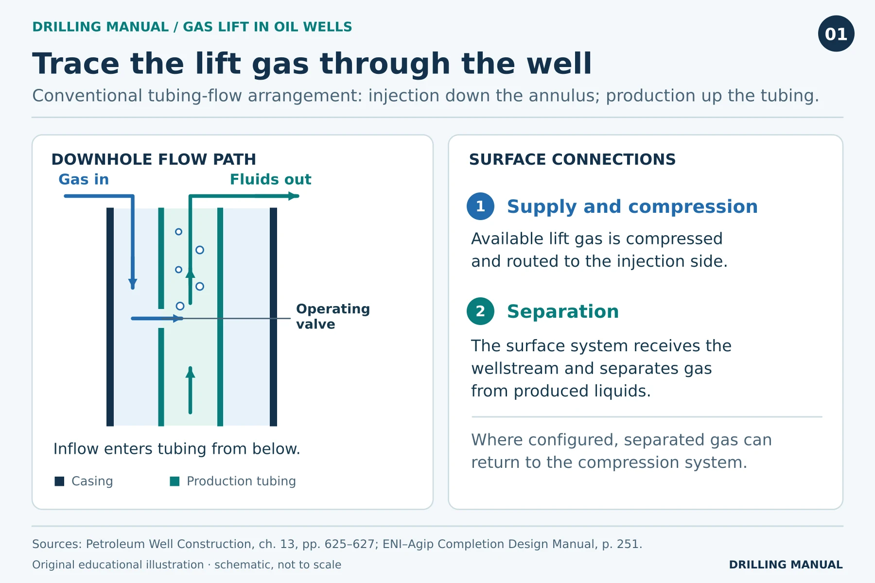
Gas entering the tubing changes the pressure gradient above the entry point. For a given wellhead pressure and liquid rate, the reservoir can therefore face a lower flowing bottomhole pressure. In contrast, fluid below the entry point has not yet mixed with the injected gas. This is why the actual depth of injection matters, even when the surface injection rate is known. [1]
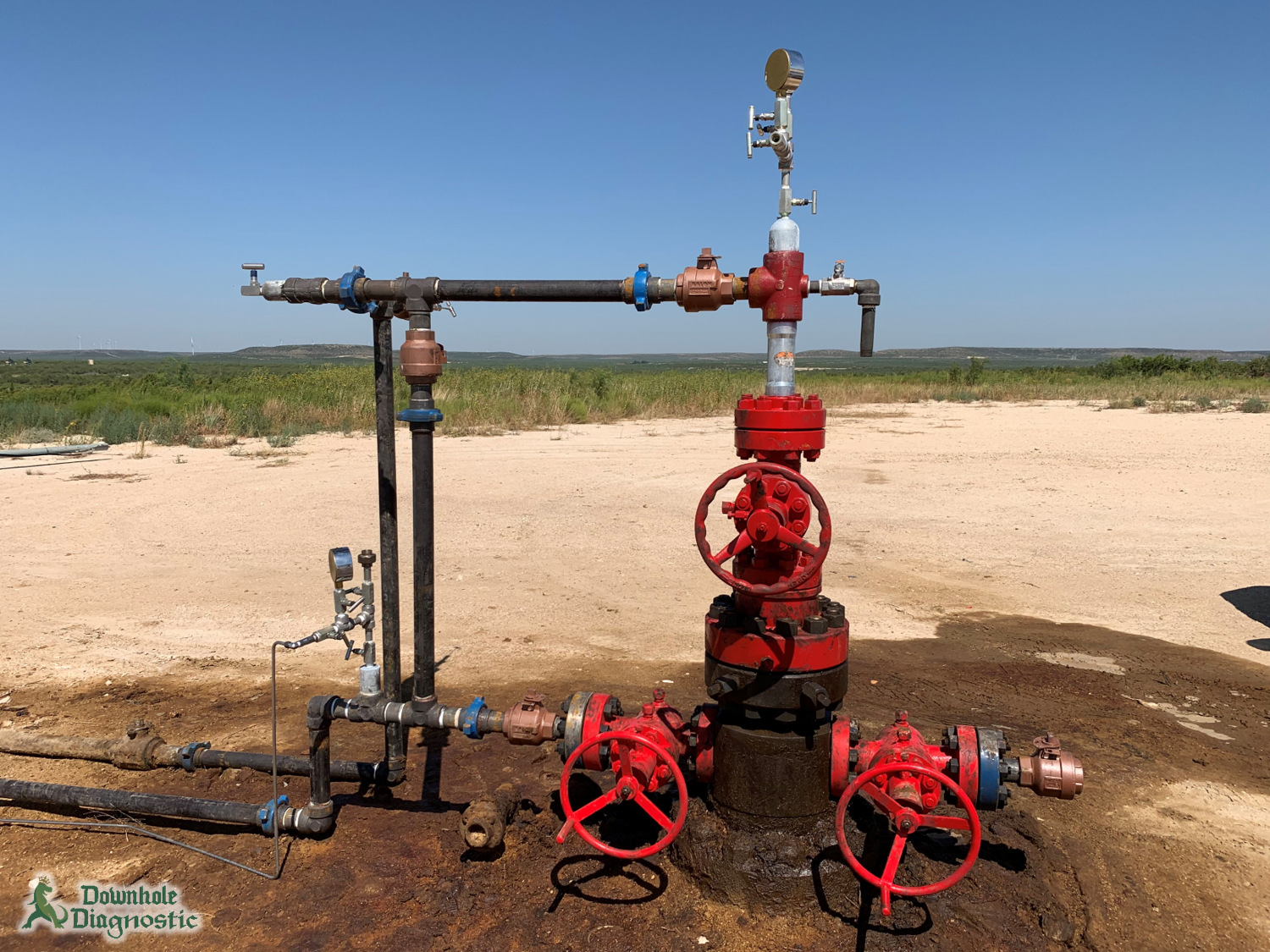
Photo: Downhole Diagnostic.
Continuous vs. Intermittent Gas Lift
| Question | Continuous lift | Intermittent lift |
|---|---|---|
| How does gas enter? | As a continuing supply during normal production. | In separate injections after liquid has accumulated. |
| What carries the liquid? | A flowing gas–liquid mixture with a lighter gradient. | Injected gas displaces a liquid slug up the tubing. |
| When is it attractive? | When reservoir inflow can support a useful sustained liquid rate. | When inflow is too small for efficient continuous operation but can refill the tubing between cycles. |
| What should a test capture? | Stabilized injection and production under comparable conditions. | Liquid delivered and gas consumed over representative complete cycles. |
For example, a high rate at the separator while a slug arrives tells you little about an intermittent well’s daily output. The well also spent time accumulating that liquid. Moreover, some liquid can fall back during the lift. Compare the liquid actually delivered per complete cycle, including the refill period, before drawing conclusions about performance. [1], [2]
Why Are Several Gas-Lift Valves Installed?
At startup, completion fluid can occupy both the tubing and the annulus. For example, the compressor may have enough pressure to reach a shallow inlet but not the intended deep inlet in a liquid-filled well. Shallower unloading valves therefore allow the transfer to take place in stages. [1], [2]
First, gas reaches an upper valve and enters the tubing there. As the tubing column lightens and annular liquid is displaced, gas can reach a deeper valve. In a typical continuous design, the upper valve then closes as injection transfers deeper. The result is one intended injection point during normal continuous production, even though several valves remain in the string. [1], [2]
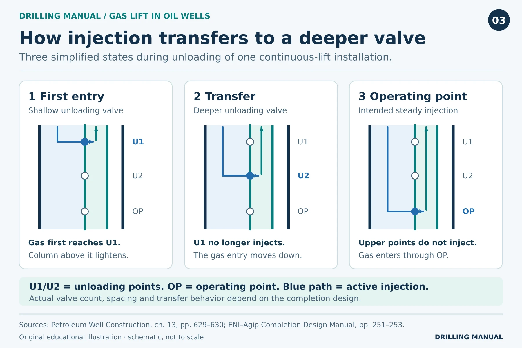
However, some intermittent designs deliberately admit more gas below a rising slug through additional valves. In contrast, an upper valve that reopens unexpectedly in a single-point continuous installation can divert gas from the intended depth. The same observation—more than one entry point—has a different meaning depending on the design. [1]
The Mandrel and the Valve Do Different Jobs
The mandrel is a section of the production string that positions the valve; the valve controls or provides the gas-entry passage. Pressure-operated valves respond to forces from tubing and injection pressures against a closing mechanism. An operating orifice, by contrast, provides an open restriction rather than opening and closing in the same way. [1]
A side-pocket mandrel holds a removable valve alongside the tubing bore. Because a slickline kickover tool can reach the insert through the tubing, the mandrel can stay in the string during valve service. With the conventional externally mounted valve described in the textbook, changing the valve requires pulling the tubing. Although the side-pocket insert is retrievable, the mandrel’s outside diameter still has to fit through the casing or liner. [1], [2]
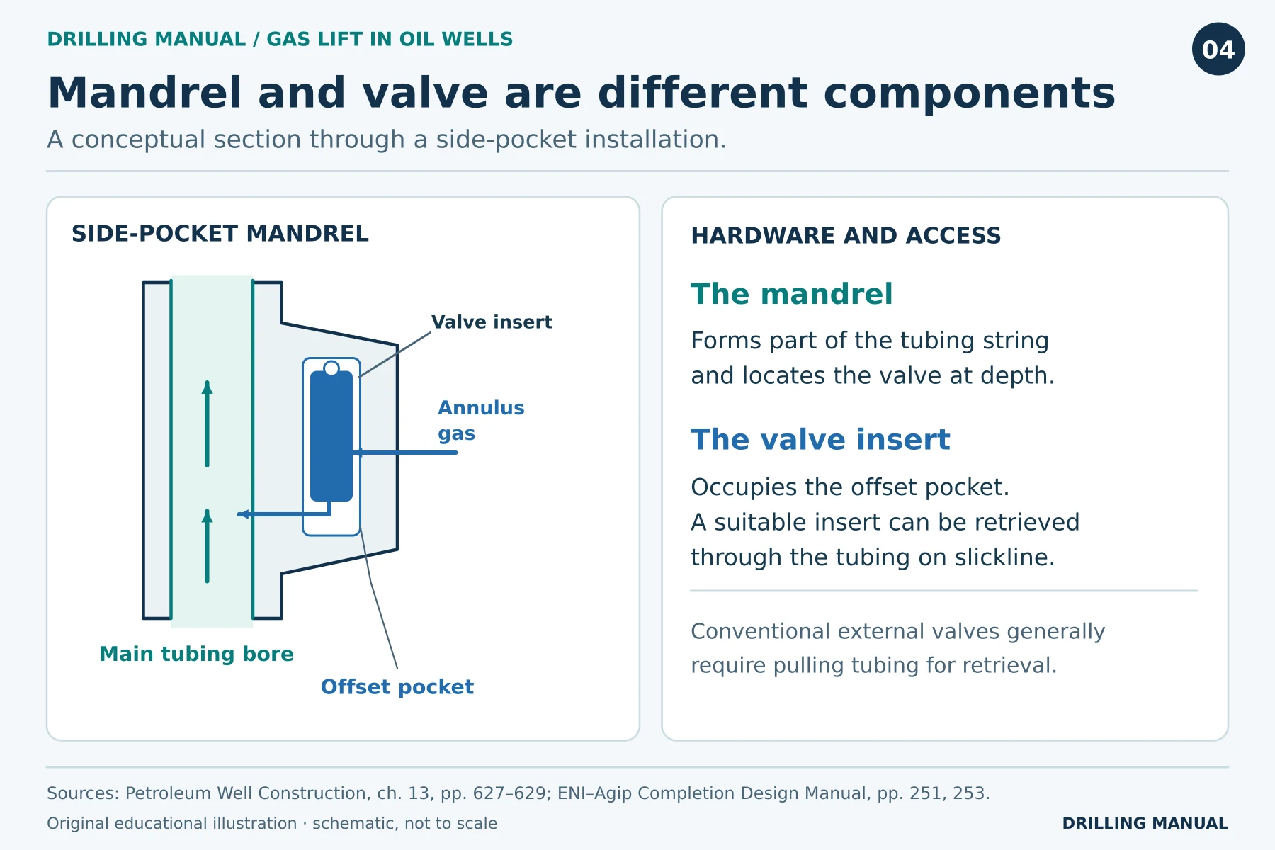
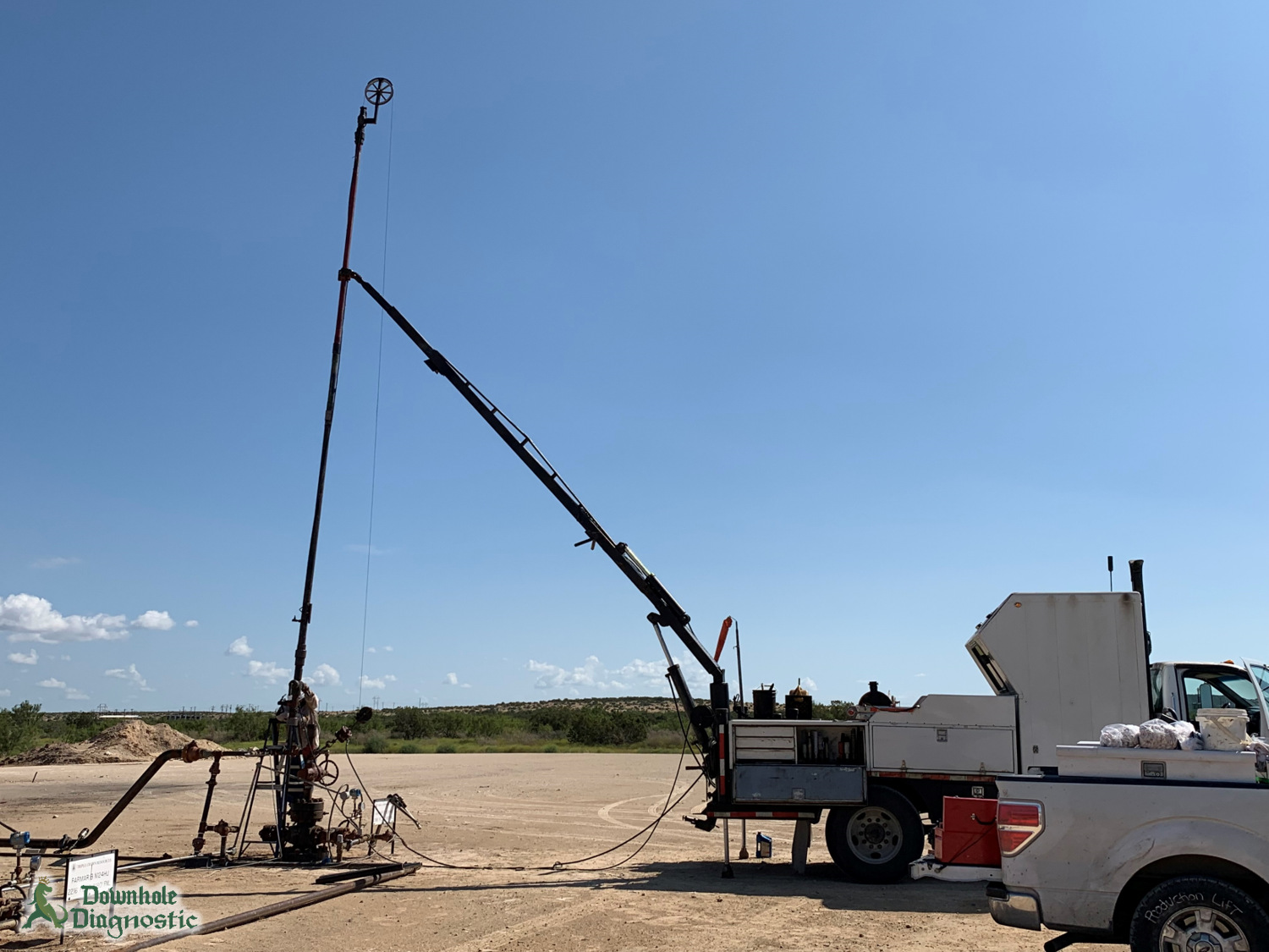
Photo: Downhole Diagnostic.
Applications and Factors Affecting Selection
Gas lift is worth evaluating in a deviated or already gassy oil well, particularly where compression and separation facilities serve several wells. In this arrangement, the injected gas supplies lift energy, so a mechanical production pump is unnecessary at the bottom of the tubing. However, that advantage has to be weighed against the gas supply, annulus pressure limits and the production packer and tubing configuration. [1], [2]
Reservoir inflow and water cut. A declining reservoir may deliver less liquid at a given flowing pressure. Meanwhile, changing water production alters the load to be lifted and the oil fraction of the recovered liquid. Consequently, yesterday’s successful injection conditions need not be the best choice for today’s well. [1], [2]
Pressure and injection depth. The deepest installed mandrel is not necessarily the deepest usable inlet. For example, a deeper inlet is useful only if the available local pressure difference can pass the required rate through its valve. The packer and mandrel locations also constrain the choice. Accordingly, surface compressor pressure alone cannot establish the active injection depth. [1], [2]
Surface capacity. Continuous lift needs a dependable gas supply. Intermittent operation also places a changing load on the separator as slugs arrive. Thus, a downhole arrangement that looks attractive may still perform poorly as part of the complete production system. [1], [2]
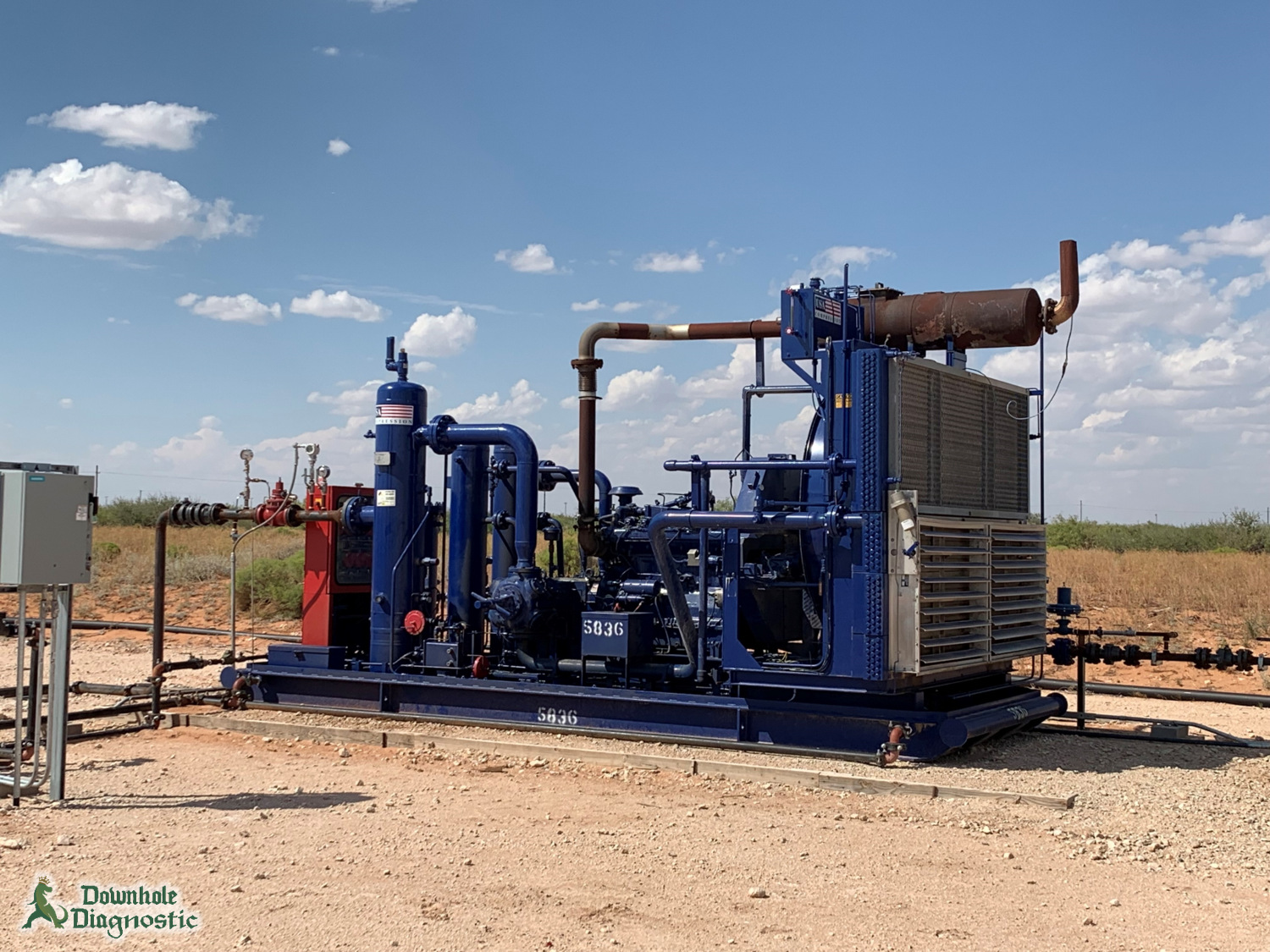
Photo: Downhole Diagnostic.
Gas Lift Calculation: What Did the Extra Gas Buy?
The following invented example compares three stabilized tests on the same continuous-lift well. Assume comparable reservoir and surface conditions and a common standard basis for gas measurement. Liquid means oil plus water. Use these assumed values only to compare responses. [1]
| Test | Gas injected (million standard ft³/day) | Total liquid (stock-tank bbl/day) | Gain over preceding test |
|---|---|---|---|
| A | 0.20 | 300 | Baseline |
| B | 0.40 | 360 | 60 bbl/day |
| C | 0.60 | 372 | 12 bbl/day |
From A to B, an extra 0.20 million standard ft³/day yields 60 additional bbl/day: 60 ÷ 0.20 = 300 barrels of liquid per million standard ft³ of extra gas. In contrast, the same increment from B to C yields only 12 ÷ 0.20 = 60 on that basis. Thus, the second increment produces one-fifth as much additional liquid as the first.
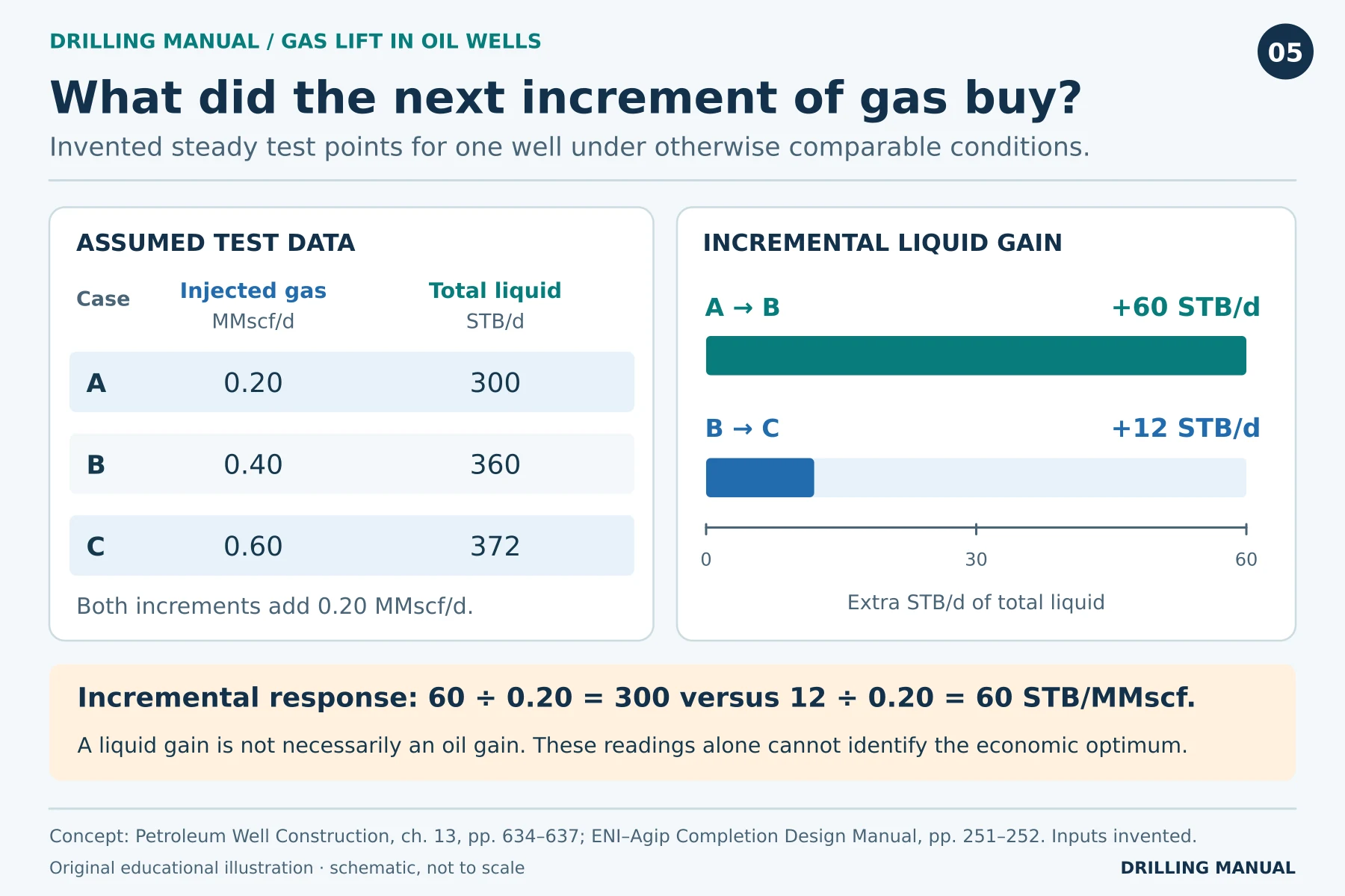
Test C has the highest liquid rate of the three. However, three tests do not locate the peak of the response curve or identify the most profitable setting. Instead, compare the value of the extra oil with the additional compression and separation costs. Also consider whether the limited gas supply would deliver more oil in a different well. [1], [2]
Reading a Production Test on a Gas-Lift Well
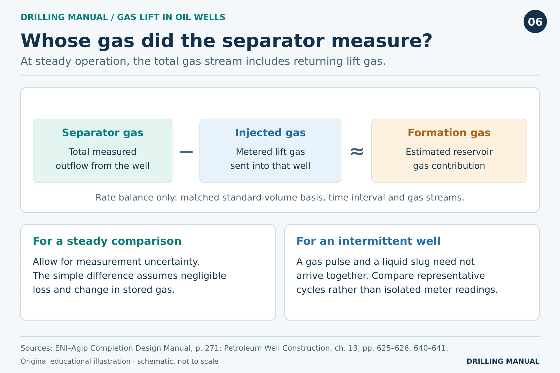
Because injected gas returns with reservoir fluids, the separator measures a combined gas stream. For a stabilized test, subtract metered injection gas from metered total gas to estimate the formation contribution. Both quantities must cover the same well, time interval and standard conditions, with the returning lift gas accounted for. Otherwise, the difference need not represent reservoir gas. [2]
For intermittent operation, compare volumes over complete cycles. Gas entering the annulus now may reach the separator later, so an instantaneous subtraction can give a misleading result. Likewise, a rise in separator gas following a rise in injection does not, on its own, show that formation-gas production increased. [1], [2]
Limitations and Rules of Thumb
- Compare pressures at the valve depth. For example, distinguish a wellhead gauge reading from a bottomhole pressure before using either in a comparison.
- Expect diminishing returns. At first, extra gas can reduce the hydrostatic component of the tubing pressure loss. Beyond a well-specific balance, additional friction can offset the benefit.
- Separate installed depth from injection depth. A drawing shows possible inlet depths, but it cannot show which valve is passing gas today.
- Match the test to the lift mode. Use comparable stable rates for continuous lift and complete cycles for intermittent lift. In both cases, distinguish oil from total liquid.
These principles do not determine a valve setting, unloading pressure or universal rate for switching modes. A design also needs fluid properties, reservoir performance, tubing geometry and the pressure limits of the actual well completion. [1], [2]
Common Gas Lift Questions
Is gas lift the same as gas injection into a reservoir?
No. Here the injection point is in the producing well’s tubing and the objective is to lift well fluids. In contrast, the target of reservoir pressure maintenance is the formation itself. [1], [2]
Does a gas-lift well need nitrogen or coiled tubing?
An installed system can use compressed produced gas and valves installed with the production tubing. A temporary nitrogen kickoff instead delivers nitrogen down a coiled-tubing string to help unload the liquid column. A well can therefore undergo a nitrogen kickoff without having a permanent gas-lift completion. [1], [3]
When might a well change from continuous to intermittent lift?
If production declines, the continuing gas supply may become uneconomic for the liquid delivered. Intermittent lift can then be assessed against the refill time, delivered slug volume, gas used per cycle and surface handling arrangements. Because those conditions vary, a single cutoff cannot settle the choice for every well. [1], [2]
Book references
- Petroleum Well Construction, John Wiley & Sons, Halliburton educational version. Chapter 13, pp. 625–633 (lift systems, valves and unloading), 634–637 (injection response and economics) and 640–641 (intermittent lift).
- ENI–Agip, Completion Design Manual, STAP-P-1-M-7100, revision 0, 28 June 1999. Section 10, pp. 250–253 and 268–271 (selection, geometry and testing). Used for operating principles; the manual’s historical example values are not field settings.
- NOV CTES, Coiled Tubing Manual, chapter 11, “Unloading a Well with Nitrogen,” p. 11-96 (physical PDF p. 393), section revision 27 June 2014. Used for the comparison with a temporary nitrogen kickoff.