What Is Coiled Tubing?
Coiled tubing (CT) is a continuous length of small-diameter steel pipe stored on a reel and used for well intervention, workover, completion, and drilling operations. Unlike conventional jointed tubing or drill pipe, coiled tubing can be continuously run into and pulled out of a well without making or breaking pipe connections.
A major advantage of coiled tubing is its ability to support intervention in a live or producing well. With an appropriately rated injector, stripper, BOP stack, and approved barrier arrangements, operators can deploy CT while managing well pressure. Some operations can proceed without first killing the well, but this depends on the well-control program and operating conditions.
Coiled tubing can pump fluids while moving and convey downhole tools into deviated or horizontal well sections, subject to friction, buckling, and available injector force. Common coiled tubing applications include sand cleanout, nitrogen lifting, acid stimulation, fishing, milling, logging, perforating, and selected drilling operations.
| Item | Coiled Tubing |
|---|---|
| Abbreviation | CT |
| Construction | Continuous steel tubing stored on a reel |
| Main use | Well intervention and workover operations |
| Deployment | Injector head |
| Pressure control | Stripper and BOP equipment |
| Can circulate fluids? | Yes |
| Live-well operations? | Yes, when properly designed and pressure controlled |
| Typical applications | Cleanout, nitrogen lifting, stimulation, fishing, milling and drilling |
| Key advantage | Continuous deployment without pipe connections |
| Key limitation | Fatigue caused by repeated bending and operational cycles |
In brief: A coiled tubing unit combines a reel, tubing string, gooseneck, injector head, power pack, control cabin, and well-pressure-control equipment. Its continuous deployment reduces connection time, but string fatigue, well pressure, friction, and buckling must be managed.
Main Components of a Coiled Tubing Unit
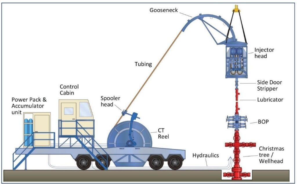
A coiled tubing unit combines the CT string with the surface equipment required to deploy, retrieve, circulate through, and safely pressure-control the tubing during operations.
The principal components are:
- Coiled tubing string
- Reel Unit
- Tubing Injector Unit: Injector head and gooseneck
- Power Pack
- Control Unit
- Stripper
- CT pressure-control equipment: stripper/packer, CT BOP, lubricator or riser sections as required, and suitable valves and connections. The exact configuration depends on well pressure, operation, and the approved well-control plan.
- Associated pumping and auxiliary equipment
Select auxiliary equipment to keep surface pressures, tensile loads, reel and injector capacities, and tubing fatigue within their approved operating limits. Job-specific equipment may include nitrogen storage and pumping units for well unloading, a mill and downhole motor for milling, or a drilling BHA for coiled tubing drilling.
Because coiled tubing equipment is modular, the required surface package varies with the job objective, wellhead interface, sour-service requirements, and pressure-control philosophy.
Service providers offer truck-mounted, trailer-mounted, skid-mounted, and other CT packages. Select the unit according to wellhead geometry, tubing size and grade, surface pressure, H2S or CO2 exposure, lifting requirements, and location constraints. In selected applications, hybrid coiled tubing systems combine CT capabilities with conventional workover functions.
For example, cleanout operations may need specialized surface separation and fluid-handling equipment, while nitrogen lifting requires appropriate nitrogen supply, pumping, and monitoring.
For detailed descriptions of the reel, injector head, gooseneck, stripper, BOPs, power pack, control cabin, and auxiliary systems, see our Coiled Tubing Equipment Guide.
Coiled Tubing Applications
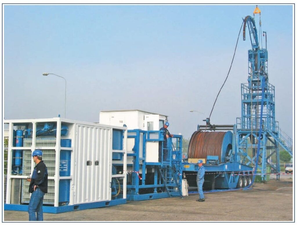
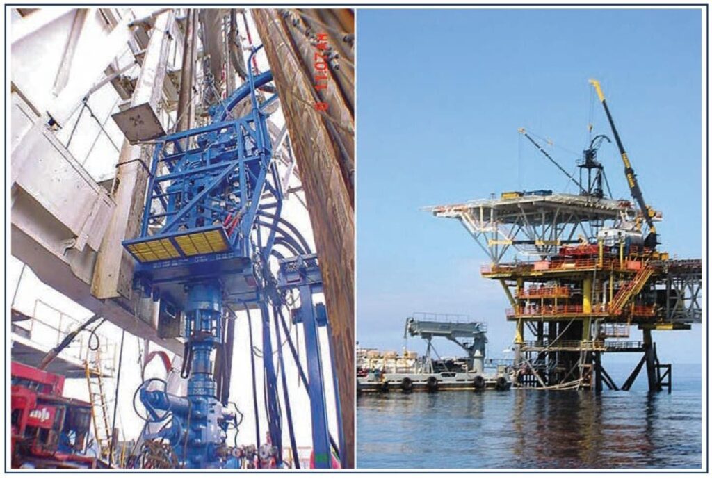
Coiled tubing is widely used for well intervention because it combines continuous pipe deployment with the ability to circulate fluids and convey downhole tools. Applications vary according to well conditions, completion design, CT size, pressure requirements, and the selected bottom-hole assembly.
Unlike conventional wireline, CT provides a continuous fluid-circulation path and can push a tool string to a limited extent. This makes it useful for selected interventions in horizontal and highly deviated wells. However, well trajectory, friction, lockup, and helical buckling can restrict achievable reach.
The following are common coiled tubing applications in workover, completion, intervention, and selected drilling programs:
Well Cleanout and Circulation
- Sand and debris cleanout
- Scale removal
- Wellbore washing
- Fluid displacement
Well Stimulation and Production
- Acid stimulation
- Nitrogen lifting and well unloading
- Chemical treatment
Mechanical Intervention
- Fishing
- Milling
- Plug and packer operations
- Operating completion equipment
Logging and Completion
- Logging in highly deviated/horizontal wells
- CT Perforating
- Completion-related intervention
Coiled Tubing Drilling
- Sidetracking
- Re-entry
- Well deepening
- Coiled tubing drilling: CT can be used for selected drilling, re-entry, sidetracking, and well-deepening operations. For detailed planning, equipment, BHA, hydraulics, well-control, and operational considerations, see our Coiled Tubing Drilling Guide.
CT String
A CT string is a continuous, high-strength steel tube supplied on a reel. Tubing grade, outside diameter, wall thickness, and service conditions determine its mechanical operating envelope. The string is flexible enough to travel over the reel and gooseneck, but repeated bending affects its remaining fatigue life.
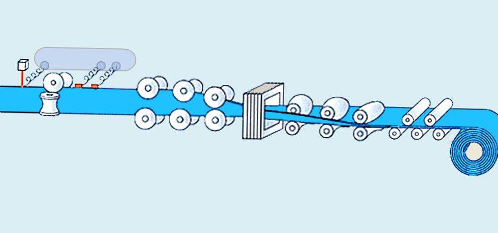
Manufacturers typically form coiled tubing from continuously processed steel strip, join successive strip lengths as required, and create a longitudinal weld as the strip passes through a forming mill. Subsequent heat treatment, inspection, and testing depend on the product and specification. API Spec 5ST covers specified grades of carbon and low-alloy steel coiled tubing; confirm the current edition, addenda, and manufacturer documentation for the actual string.
When CT bends around the reel and gooseneck, the outer and inner walls experience repeated tensile and compressive strain. Bending may exceed the elastic limit, creating plastic strain; repeated bending and straightening contribute to low-cycle fatigue. Fatigue accumulation also depends on tubing dimensions, material, internal pressure, and operating history. Track each string’s fatigue life using the approved service-provider model and inspection program.
Running CT In and Out of the Well
The CT injector head grips the tubing with opposing chains and supplies the force needed to run it into or pull it out of the well. The reel drive and braking system manage back tension and orderly spooling. Injector grip force, reel tension, wellhead pressure effects, and tubular loading must remain within the unit’s operating limits.
As CT passes over the gooseneck and through the injector, it is guided toward the pressure-control stack. During retrieval, the injector reverses direction and the reel takes up tubing under controlled back tension. Operators monitor depth, weight, pressure, and equipment response throughout the movement.
CT Barriers
For live-well operations, a dynamic stripper/packer seals around the moving tubing while a suitably configured CT BOP and pressure-control stack supplies additional well-control functions. Internal check valves in the CT BHA may prevent reverse flow inside the string. Barrier status must be assessed for each flow path: an external seal does not automatically provide an independent internal barrier, and check valves must meet the approved barrier and testing requirements. Use the operator’s well-specific pressure-control program.
Coiled Tubing vs Drill Pipe vs Wireline
| Feature | Coiled Tubing (CT) | Drill Pipe | Wireline |
|---|---|---|---|
| Deployment | Continuous tubing; no connections are required during normal tripping – RIH or POOH | Jointed pipe; operations stop periodically to make or break connections | Continuous cable deployment; generally fast for suitable intervention operations |
| Fluid circulation | Yes. Fluids can be pumped through the CT while stationary or moving | Yes. Provides high circulation capability depending on the drillstring and pumping system | Conventional wireline does not provide a circulation path through the cable |
| Axial force/tool conveyance | Can apply both tensile force and limited compressive force to the BHA | Can transmit substantial tensile and compressive loads | Primarily operates in tension and has limited ability to push tools downhole |
| Highly deviated and horizontal wells | Well suited, although reach can become limited by friction and helical buckling | Good reach and load capacity; rotation can also help reduce drag | Gravity conveyance becomes increasingly difficult as inclination increases; alternative conveyance methods may be required |
| Drilling capability | Can perform CT drilling using a downhole motor or other suitable BHA | Primary tubular used for conventional rotary and directional drilling | Conventional wireline is not used as the drillstring for drilling operations |
| String rotation | The CT string is normally not rotated from surface; downhole motors can provide BHA/bit rotation | Drill pipe can transmit surface rotation directly to the BHA types and drilling bit | The cable does not provide continuous drillstring-type rotation |
| Well intervention | Excellent for cleanout, circulation, nitrogen lifting, stimulation, milling, fishing and other intervention work | Suitable for heavy workover, drilling and operations requiring greater axial or torsional capability | Excellent for logging, setting/retrieving selected tools, perforating and other light intervention operations |
| Buckling / reach limitation | Susceptible to sinusoidal and helical buckling when compressive force increases; this can limit reach in deviated/horizontal wells | Greater stiffness and ability to transmit axial load, although buckling and drag must still be considered | Limited push capability because the cable is flexible and normally maintained in tension |
| Friction and drag | Friction increases with depth, inclination and tortuosity and can limit CT reach and available force at the BHA | Generally provides greater mechanical capability for overcoming drag, especially when rotation is available | Friction and loss of gravity conveyance can significantly restrict access in highly deviated wells |
| Pressure-control capability | Well suited to live-well intervention when used with the appropriate stripper, BOPs and pressure-control equipment | Live-well deployment requires specialized equipment and procedures, such as snubbing | Wireline pressure-control equipment can allow intervention on live wells |
| String life | Fatigue accumulates as CT bends and straightens over the reel and gooseneck; CT fatigue life must be monitored using the string history and an approved fatigue model | Drill pipe life depends on fatigue, wear, corrosion, connection condition and accumulated service | Wireline life depends on cable type, mechanical loading, bending, wear, corrosion and service history |
| Main advantage | Combines continuous deployment, circulation and the ability to apply force at the BHA | Generally greater axial and torsional capability for drilling and heavy-duty operations | Fast, relatively simple conveyance for logging and many intervention operations |
| Main limitation | Fatigue, buckling, friction | Connections increase trip time and require more substantial handling equipment | Limited push force and no conventional fluid-circulation path |
Coiled Tubing Sizes and Capacities
Common coiled tubing outside diameters for intervention include 1½, 1¾, 2, 2⅜, and 2⅞ in., while smaller and larger sizes are also used. The correct tubing size depends on reach, flow requirements, collapse and burst loads, injector capacity, and the well completion. See the Coiled Tubing Handbook for additional background.
How to read the coiled tubing capacity chart: Each row gives an outside diameter (OD), nominal weight, inside diameter (ID), and equivalent internal-fluid volumes per unit length. Rows with a blank OD belong to the last stated OD above them. The listed capacities are nominal reference values, not pressure ratings or substitutes for a manufacturer’s string certificate.
Capacity calculation: For a circular tube with a uniform internal diameter, internal capacity (bbl/ft) ≈ ID² ÷ 1,029.4, where ID is in inches. For example, a 2-in. OD string with a 1.750-in. ID holds approximately 0.00298 bbl/ft (about 0.125 gal/ft). Confirm the actual ID, any variable-wall sections, and operational volume allowance before planning fluid displacement.
| Size OD in | Weight (lb/ft) | ID in | Capacity (bbl/ft) | Length (ft/bbl) | Capacity (ft³/ft) | Length (ft/ft³) | Capacity (gal/ft) | Length (ft/gal) |
| 1 | .743 | .850 | .00070 | 1424.8 | .00394 | 253.77 | .0295 | 33.924 |
| .850 | .826 | .00066 | 1508.8 | .00372 | 268.73 | .0278 | 35.924 | |
| .920 | .810 | .00064 | 1569.0 | .00358 | 279.45 | .0268 | 37.357 | |
| .981 | .796 | .00062 | 1624.6 | .00346 | 289.37 | .0259 | 38.683 | |
| 1.040 | .782 | .00059 | 1683.3 | .00334 | 299.82 | .0250 | 40.080 | |
| 1 1/4 | .944 | 1.100 | .00118 | 850.7 | .00660 | 151.53 | .0494 | 20.256 |
| 1.083 | 1.076 | .00112 | 889.1 | .00631 | 158.36 | .0472 | 21.170 | |
| 1.175 | 1.060 | .00109 | 916.2 | .00613 | 163.18 | .0458 | 21.814 | |
| 1.254 | 1.046 | .00106 | 940.9 | .00597 | 167.58 | .0446 | 22.402 | |
| 1.332 | 1.032 | .00103 | 966.6 | .00581 | 172.16 | .0435 | 23.014 | |
| 1.506 | 1.000 | .00097 | 1029.4 | .00545 | 183.35 | .0408 | 24.510 | |
| 1.601 | .982 | .00094 | 1067.5 | .00526 | 190.13 | .0393 | 25.417 | |
| 1.827 | .938 | .00085 | 1170.0 | .00480 | 208.39 | .0359 | 27.857 | |
| 2.014 | .900 | .00079 | 1270.9 | .00442 | 226.36 | .0330 | 30.259 | |
| 1 1/2 | 1.429 | 1.310 | .00167 | 599.8 | .00936 | 106.84 | .0700 | 14.282 |
| 1.527 | 1.296 | .00163 | 612.9 | .00916 | 109.16 | .0685 | 14.593 | |
| 1.623 | 1.282 | .00160 | 626.3 | .00896 | 111.56 | .0671 | 14.913 | |
| 1.840 | 1.250 | .00152 | 658.8 | .00852 | 117.34 | .0638 | 15.686 | |
| 1.960 | 1.232 | .00147 | 678.2 | .00828 | 120.80 | .0619 | 16.148 | |
| 2.245 | 1.188 | .00137 | 729.4 | .00770 | 129.91 | .0576 | 17.366 | |
| 2.483 | 1.150 | .00128 | 778.4 | .00721 | 138.64 | .0540 | 18.533 | |
| 1 3/4 | 1.915 | 1.532 | .00228 | 438.6 | .01280 | 78.12 | .0958 | 10.443 |
| 2.175 | 1.500 | .00219 | 457.5 | .01227 | 81.49 | .0918 | 10.893 | |
| 2.318 | 1.482 | .00213 | 468.7 | .01198 | 83.48 | .0896 | 11.160 | |
| 2.662 | 1.438 | .00201 | 497.8 | .01128 | 88.67 | .0844 | 11.853 | |
| 2.951 | 1.400 | .00190 | 525.2 | .01069 | 93.55 | .0800 | 12.505 | |
| 2 | 2.207 | 1.783 | .00309 | 323.8 | .01734 | 57.67 | .1297 | 7.710 |
| 2.509 | 1.750 | .00297 | 336.1 | .01670 | 59.87 | .1250 | 8.003 | |
| 2.677 | 1.732 | .00291 | 343.2 | .01636 | 61.12 | .1224 | 8.170 | |
| 3.080 | 1.688 | .00277 | 361.3 | .01554 | 64.35 | .1163 | 8.602 | |
| 3.419 | 1.650 | .00264 | 378.1 | .01485 | 67.35 | .1111 | 9.003 | |
| 2 3/8 | 3.011 | 2.125 | .00439 | 228.0 | .02463 | 40.60 | .1842 | 5.428 |
| 3.215 | 2.107 | .00431 | 231.9 | .02421 | 41.30 | .1811 | 5.521 | |
| 3.706 | 2.063 | .00413 | 241.9 | .02321 | 43.08 | .1736 | 5.759 | |
| 4.122 | 2.025 | .00398 | 251.0 | .02236 | 44.71 | .1673 | 5.977 | |
| 4.445 | 1.995 | .00387 | 258.6 | .02171 | 46.07 | .1624 | 6.158 | |
| 2 7/8 | 3.932 | 2.607 | .00660 | 151.5 | .03707 | 26.98 | .2773 | 3.606 |
| 4.554 | 2.563 | .00638 | 156.7 | .03583 | 27.91 | .2680 | 3.731 | |
| 5.059 | 2.525 | .00619 | 161.5 | .03477 | 28.76 | .2601 | 3.844 | |
| 5.462 | 2.495 | .00605 | 165.4 | .03395 | 29.45 | .2540 | 3.937 | |
| 3 1/2 | 6.230 | 3.150 | .00964 | 103.7 | .05412 | 18.48 | .4048 | 2.470 |
| 6.733 | 3.120 | .00946 | 105.7 | .05309 | 18.84 | .3972 | 2.518 |
Frequently Asked Questions About Coiled Tubing
Can coiled tubing be used in a live well?
Yes, when the well-specific program permits it and suitable pressure-control equipment and verified barriers are available. Live-well deployment is not automatically safe merely because a CT unit has a stripper and BOP.
Why does coiled tubing experience fatigue?
Reeling, guiding, and straightening the tubing impose repeated bending strains. The combination of bend cycles, internal pressure, material properties, and prior use determines how much fatigue life remains.
How do you calculate coiled tubing internal capacity?
Using ID in inches, divide ID squared by 1,029.4 to estimate barrels per foot. Multiply by length in feet for a uniform-ID string; use the actual sectional ID and manufacturer data if the string has variable wall thickness.