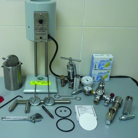
What Is The Drilling Fluid Test HPHT Filter Press?
The HPHT filter press fluid loss test, which is differ from API filter press fluid loss test, is used for measuring fluid loss for all types of drilling fluids at elevated temperature and pressure. A sample of mud is pressurized in a chamb er while the volume of filtrate that passes through filter paper over a specified time period is measured. The quality and thickness of the filter cake deposited on the filter paper is also checked after the device has been dismantled for cleaning. In this article we will mention the fluid loss test procedure as per API recommendation.
Fluid loss control is not so important for surface hole sections, but it is important for deeper sections because it gives an indication of the mud filtrate that invades the formation. Drilling fluids with poor fluid loss control (i.e. high fluid loss) produce thick filter cakes that can encourage differential pipe sticking and other hole problems. Drilling fluids with good fluid loss control (i.e. low fluid loss) produce thin filter cakes that minimize shale hydration and improve drilling performance (Penetration Rate (ROP)).
What Is The Potential Problems That Can Happen Due To Excessive Filtrate Invasion?
- Formation-evaluation difficulties thanks to excessive filtrate invasion, poor transmission of electrical properties through thick wall cakes, and off course higher chance of getting problems while running open hole logging tools. Erroneous properties measured by logging tools (measuring filtrate altered properties instead of reservoir fluid properties).
- Unable to perform sampling test for formation fluids. As the tool arms will withdraw the filtrate rather than the formations fluid.
- Formation damage thanks to filtrate and solids invasion. Damaged zone too deep to be cured by perforation or stimulation jobs. Damage could be precipitation of insoluble compounds, changes in wettability of oil and gas, changes in related permeability, formation plugging with fines or solids, and swelling of in-situ clays.
- Oil and gas zones could also be overlooked because the filtrate is flushing hydrocarbons faraway from the wellbore, making detection harder.
What Is The Potential Problems That Can Happen Due To Excessive Filter Cake Thickness?
- Increased surges and swabbing effects as a result of lower annular clearance.
- Tight spots while tripping pipe that can result in increased drag.
- Casing cementing difficulties because of improper displacement of wall cake.
- Differential Stuck of the Drill String as result of higher contact area and faster development of stuck forces resulted from increased filtration rate.
- Casing Running will be more difficult.
The General Idea Of HPHT Filter Press Test For Drilling Fluid:
The HPHT filter press drilling fluid test is used for measuring the filtration and filter-cake building properties of the drilling fluid at elevated temperature and pressure. The instrument comprises a mud cell that can be pressurized with back-pressure through valve stems. The mud cell is placed in a thermostatically controlled heating jacket and heated to the required temperature (usually 300°F or 148°C). The mud cell is then pressurized to 600 psi, with 100 psi back-pressure, to provide 500 psi differential pressure while measuring the volume of filtrate recovered over a 30-minute period.
The reason for applying back-pressure is to prevent evaporation of the hot filtrate, which would distort results. Note that the HPHT filter paper size is half the API filter paper size, so the HPHT filtrate volume recovered over the 30-minute test period must be doubled. Caution is required when running the HPHT filter press due to the high temperatures and pressures, and the condition of the HPHT filter press components and seals must be checked carefully for signs of damage.
Care is required when dismantling the cell after running a test because the mud could still be hot.
The pressure in the mud cell is released by carefully opening valve stems on the mud cell. The reduction in pressure could cause the mud to boil and escape through the valve stem. For this reason, stand clear while the pressure is being released and cover the valve stem with a piece of cloth if necessary. Care is also required when releasing the locking screws to remove the lid, in case of trapped pressure due to a plugged valve stem.
The Drilling Fluid HPHT Filter Press Fluid Loss Test Procedure
The following fluid loss test procedure is used for measuring HPHT fluid loss control:
- Switch the heating jacket on and leave to warm up, inserting a dial thermometer in the small hole in the body of the heating jacket to monitor the temperature.
- Check that the valve stem for the mud cell is not plugged, screw into the mud cell body and close the valve stem using an adjustable spanner
- Check that the locking screws around the mud cell have all been retracted and do not intrude into the internal surface of the mud cell.
- Fill the mud cell with a sample of mud, leaving a ½” gap below the O-ring groove to allow for heat expansion.
- Check that the O-ring in the mud cell is undamaged and seated correctly, and place one of the HPHT filter papers on top.
- Check that the O-ring around the lid is undamaged, align the recesses in the lid with the locking screws in the body, and push the lid firmly down onto the mud cell body (a smear of high temperature grease on the lid O-ring will make this easier)
- Use an Allen Key to engage the locking screws in the lid and tighten evenly before closing the filtrate discharge valve stem in the lid with an adjustable spanner.
- Place the mud cell in the heating jacket with the filtrate discharge valve stem facing down, and rotate the mud cell until it slots into a pin in the bottom of the heating jacket.
- Insert a dial thermometer in the small hole in the mud cell to monitor the temperature.
- Insert a new CO2 cartridge in the pressure assembly, place on the upper valve stem of the mud cell and insert the locking pin.
- Adjust the pressure regulator to apply 100 psi and open the upper valve stem with a ½-turn to pressurize the unit and stop the mud from boiling as it is brought up to the required temperature.
- Insert a new CO2 cartridge in the back-pressure assembly, place on the lower valve stem and insert the locking pin.
- When the mud cell reaches the required temperature (usually 150°C or 300°F), adjust the pressure regulator on the lower valve stem to apply 100 psi back-pressure, but leave the valve closed.
- Adjust the pressure regulator on the upper valve stem to increase the pressure in the mud cell from 100 psi to 600 psi.
- Open the lower valve stem with a ½-turn and record the start time.
- Monitor the back-pressure during the test and bleed off any increases in pressure by draining filtrate into a graduated glass measuring cylinder to maintain the 500 psi differential pressure.
- When the 30 minute test period is over, close the lower and upper valve stems, close the pressure regulators, and pull the red bleed-off knobs to release trapped pressure.
- Drain residual filtrate into the graduated glass measuring cylinder and record the volume of filtrate collected in milliliters (this figure needs to be doubled when reporting the HPHT fluid loss, because the area of the HPHT filter paper is half that of the API filter paper).
- Remove the locking pins and remove the upper and lower pressure assemblies.
- Lift the hot, pressurized mud cell out of the heating jacket, place in a safe area (e.g. fume cupboard), and leave to cool in an upright position.
- When mud cell is cool, bleed off the cell pressure by carefully opening the valve stems.
- Use an Allen Key to carefully loosen the locking screws in the lid of the mud cell (check for residual trapped pressure), and carefully dismantle the mud cell without damaging the filter cake on the filter paper.
- Remove the filter paper and gently rinse off the surface mud on the filter cake.
- Measure the thickness of the filter cake to the nearest 1/32 nd of an inch, and note any relevant observations about filter cake quality (e.g. firm, slick, etc.).
- The filtrate collected in the graduated glass measuring cylinder should be thrown away as it cannot be used for mud checks.
- Remove the used CO2 cartridge from the pressure assemblies.
- Wash the mud cell components thoroughly and leave to dry, in preparation for future tests.
HPHT Filter Press Test Procedures Video
HPHT Filter Press Fluid Loss Test Procedure Video Part 1
HPHT Filter Press Fluid Loss Test Procedure Video Part 2
HPHT Filter Press Fluid Loss Test Procedure Video Part 3
Fluid Loss Related Papers
- Investigation of drilling fluid loss and its affecting parameters in one of the Iranian gas fields
- Effect of Drilling Fluid Filter Cake Thickness And Permeability On Cement Slurry Fluid Loss
- Static and Dynamic Fluid-Loss Characteristics of Drilling Fluids in a Full-Scale Wellbore
Remember If you need any paper just contact me on my Facebook Page (Drilling Manual)