The casing pipe is mandatory in drilling operations as it has a lot of casing functions to prevent cave-in of unconsolidated formations, isolate problem zones, and many more. As mentioned before in our casing design guide, the selection of casing depends on many factors. Here in this article, we shall learn everything about the best drilling practices for casing running procedures, tools & equipment. In other words, you will learn the proper procedure for the casing running in the hole. In addition, you can use it in your drilling rig floor program or game plan.
Preliminary Operations
Before Starting the Job
Before commencing the casing running procedures & its job, the Toolpusher, Driller, Cementing Operator, Mud Engineer, and Mud Logging Operator shall have complete data related to the Casing Cementing Job Procedure such as:
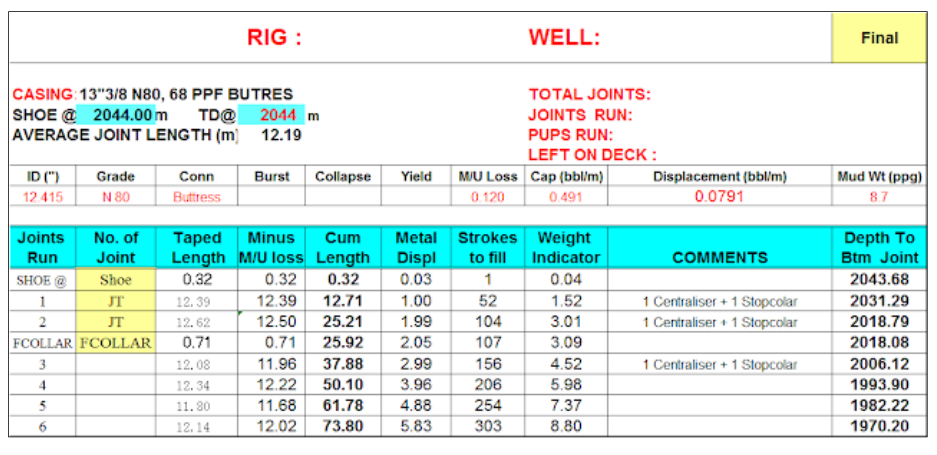
- Prepare the casing tally.
- The total amount of lead and tail cement slurries.
- Volumes, density, and composition of spacers.
- Calculated top of tail and lead slurries based on hole conditions.
- The desired density of lead and tail slurries.
- The required amount of mixing water for both slurries (fresh or sea water to be duly noted by all concerned).
- The total amount of cement that we plan to use.
- Required volumes of additives for both slurries.
- Estimated setting time of the cement.
- The internal volume of casing from top to float collar and the number of rig pump strokes to bump the cementing plugs.
- The casing pipe capacity from float collar to float shoe and number of rig pump strokes for over displacement only.
- Maximum allowable displacement rate compatible with the MAASP (How to Calculate MAASP).
First Steps
- First, Check The Casing And Cementing CheckList
- After opening the hole log, it is preferable to perform a tripping pipe to the bottom to condition the hole and mud (Wiper Trip). The Mud Engineer shall check and, if necessary, adjust the mud properties. Keep Plastic viscosity, yield strength, and weight as low as possible.
- There is a difference between the driller’s and logging depths. We should consider strapping in or out of the Drill String.
- Check the weather forecast to ensure conditions allow safe operations.
- Replace the upper pipe BOP rams with the correct size of rams for the next casing. When changing the pipe rams, perform a pressure test of the bonnet and ram seals. Remember, a Blowout preventer may be required for any Well Control issue.
- Retrieve the wear bushing.
After Retrieving Wear Bushing
- Do not lay down the Bottom Hole Assembly BHA unless unavoidable. Before running the 7″ casing, break out the BHA and 5″ Drill Pipe. After the Casing Cementing Job, while waiting on cement, lay down the BHA and 5″ DP.
- The log determines the correct volume of slurry and spacers from the caliper. Centralization Pattern to be used.
- Verify that the differential pressure between the slurry and mud does not exceed the Casing Collapse Rating. Also, ensure that the slurry density and the planned top of cement do not cause losses of circulation and/or gas migration while waiting on cement.
- The Company Completion and Drilling Supervisor, Company Drilling Engineer (if on site), and Cementing Operator shall conduct individual calculations for the cementing job before running the casing. The figures/calculations shall be compared to ascertain the final cement, volumes, etc.
- Calculate the Maximum Allowable Overpull while running casing, as for the Drill String.
- Landing joints are to be inspected and selected to avoid interference with the wellhead. The coupling must be at least 2m from the casing hanging point.
Final Advice
- Do not start running the casing without the Cementing Operator being on site. The operator will start the unit pumps and check for system malfunctions.
- Check the length of elevator links several days in advance for fitness with casing running tools & equipment, i.e., spider, circulating/cementing heads, and circulating casing packer.
- Install Casing Centralizers as per the drilling program when the casing is on the pipe rack to avoid time-wasting during casing running.
- Check shoe and collar integrity.
- Test the sealing adapter 30″-20″ shoe for a perfect fit.
- Record initial pit levels to establish a reference volume to detect abnormal conditions while running the casing.
- Arrange an appropriate length of high-pressure flexible hose for casing string circulating down and/or reciprocating.
- Center the traveling block with the rotary table to facilitate casing running and hanging.
- Check subs, crossovers, stage collars, and ECIP for correct threads, dimensions, etc.
- Inspect the casing’s internal surface on the pipe rack to ensure all joints are free from foreign matter.
Casing Running: Pre-job Safety Meeting
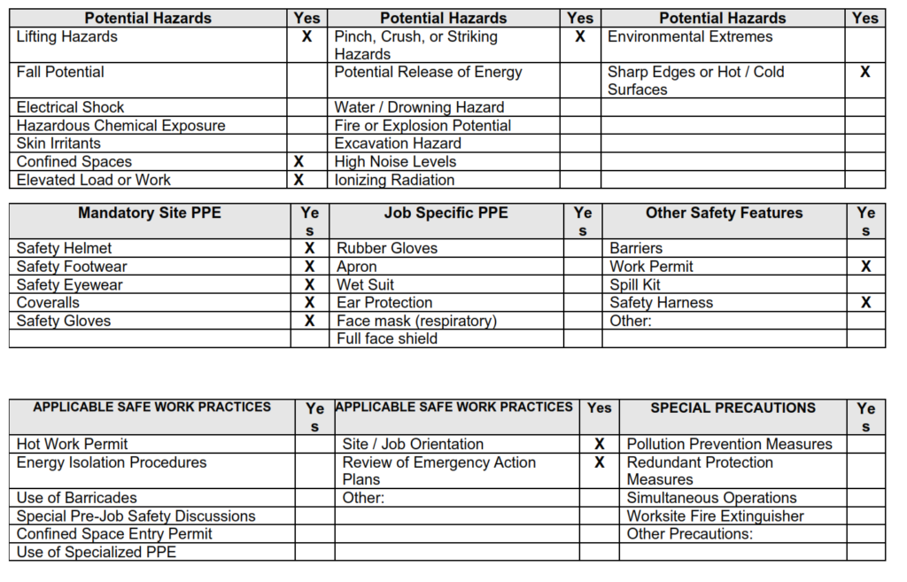
Before starting casing, the drilling supervisor should hold a pre-job safety meeting and confirm the following with the crew:
- Remove unnecessary tools.
- Good Housekeeping before the job
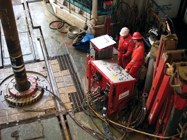
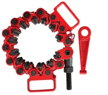
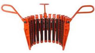
- Rig up Casing handling equipment: Using appropriate hand tools while handling the power tong is important. You must also take extra care to ensure the safety of the hydraulic hoses. Always be cautious around caught-in-between and pinch-point areas. When using slings and shackles, make sure to secure them with safety pins. Additionally, all loose lifting tools should be color-coded for easy identification. Lastly, ensure that the running board over the spider slips is safe to use.
- Stabbing Board: Ensure that all safety devices and locking mechanisms are in good condition, avoid pinch points, and keep the stabbing board folder clear from the top drive. Additionally, verify that the stabbing board is certified.
- Ensure that the tubing is in good condition and that there is no blocking inside the tubing.
- When latching the first joint in the elevator, carefully lower it while guiding it with the drilling crew. Secure the air hoses with safety wires.
- When setting the slips, move the block slowly. Each person should pull, hold, and set the slips together. Be sure the elevator does not hit the slip handle.
- As soon as the slips are around the casing, let it fall and ride down with string movement. Do not press the slips with the feet inside the bowls.
- Only one person should exist to give hand signals to the PC operator
- The TRS operators should review the stabbing board before using it, and they must always buckle the stabbing board safety belt. Comply with the recommended torque and have good communication between the power tong operator and jam unit operator.
- Release residual pressure from the hydraulic hoses via a safe method.
Casing Running Procedures
- A circulation sub, fitting the casing thread, equipped with a WECO connection, shall be readily available on the rig floor at all times during casing running.
- The most forgotten casing running procedure is to pick up the shoe joint and remove the blank thread protector at the V-door. Lower the joint through the rotary and visually verify for backflow. Fill the joint with mud, then pick it up to check for flow through.
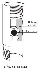
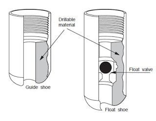
- Generally, a float collar shall be run two joints above the shoe in 13 3/8″ and 9 5/8″ casing and three joints above a 7″ shoe, 30″ conductor casing pipe, after drilling of 36″ hole and 20″ surface casing shall be cemented using a Drill Pipe inner string with a sealing sleeve adapter.
- Use a thread lock compound on all the connections on and below the float collar (or landing collar).
- Pick up the collar joint and remove the blank thread protector at the V-door. Make up the joint and fill it with mud. Pick up and check the shoe and collar for flow through.
- After casing running six joints, make up the circulating head and test the float equipment pumping at the maximum displacement rate. Record pressure losses due to collar and shoe at various flow rates.
- When running the Buttress casing, connect the first ten joints to the reference triangle (do not consider the joints between the shoe and collar since the torque transmission factor of the thread lock compound is not the same as the casing dope). Record the average torque required for these first joints and use it for the remaining string. The torque value shall be checked every 10-20 joints and adjusted if necessary.
- The makeup torque should follow the manufacturer’s specifications when casing running procedures for other threads.
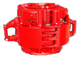
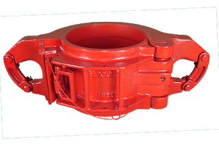
- Rotary slips with safety clamps and side door elevators may be used up to a weight equal to 60% of the rating for the elevators. Beyond this weight, use a slip-power elevator and spider.
Note: Slip power elevator and spider shall always be used when running casing in open hole

- Stop the block before setting the spider, and then slowly slack off the pipe weight to minimize pipe slippage, notching, or slip crushing.
- We should calculate the speed of the maximum casing running procedures for the well-specific mud properties and formation integrity (formation integrity test). As a rule of thumb, running speed should never exceed 0.6m/sec. (20sec/joint) inside casing and 0.3m/sec. (40sec/joint) in an open hole.
Note : For 7″ casing the running speed shall not exceed 0.2m/sec. (1 joint every minute).
- Inform the Driller that speed variation causes surge and possible mud loss, so running the casing as smoothly as possible is particularly important.
- Fill up the casing after every joint and completely every ten joints. If running a casing liner (one of the Types Of Casing), fill up the running string at each stand.
- While running the casing, compare the actual string weight and pit level with previously plotted theoretical values to detect any possible abnormal conditions.
- Intermediate circulation is generally not necessary. However, it may be advisable under the following circumstances:
- When the weight indicator shows excessive dragging or a tendency to stick.
- When expecting an excessive amount of mud cake, cuttings, or shale.
- It is anticipated that returns will be lost if excessively high pump pressure is required to break circulation at the bottom.
- At the previous casing shoe, circulation should start at a very low pump rate and gradually increase to the maximum displacement rate. Record the circulating pressures at various rates.
- When installing a production casing string, placing a short joint near the pay zone will aid in checking depths with the casing collar locator (CCL) during later logging operations.
- During casing running, plot the casing weight and pit levels on the graph (described earlier) and compare them with the theoretical values previously plotted to detect any possible abnormal conditions.
- At the previous casing shoe depth, fill up the string completely and circulate the volume inside the casing. Check levels and start circulation at a very low pump rate, gradually increasing to the maximum allowable displacement rate. Record the circulating pressures at the various flow rates.
- Space out the casing string so that the cementing head is at a convenient height. Ensure that the last casing collar is not across the hanging point.
- With the casing at TD, circulate the total hole volume, following the procedure in step 19.
- During circulation, check the levels and any bottom cushion. Record the pressure with the estimated displacement rate at the end of circulation.
- During the final circulation and the following cementing job phases, hang the casing on the traveling block and do not leave it on the rotary table clamp.
Note : In particular instances the ‘Post Plug’ technique should be used in order to reciprocate the casing string.
Casing Running Operations With A Top Drive
- With the introduction of 500 tons of bails and an adequately rated swivel, the Top Drive is rated at 500 tons for casing operations. We must use longer bails (132” or 144”) to allow clearance for the casing elevator under the torque wrench in the pipe handler.
- Also, we must consider clearance for the cementing head when determining casing bail length. Attaching a short piece of hose to the saver sub in the pipe handler can fill the casing while lowering by using the remotely controlled Kellycock to start and stop the calculated filling flow. If desired, the casing can be run conventionally using the block and hook by swinging the Top Drive aside. Very long bails must prevent the block from contacting the Top Drive dolly.
- Prepare landing/circulating heads (4 1/2″ If Box connections) connected directly to the top drive for 13 3/8″, 9 5/8″, and 7″ casing. This will facilitate circulating down, casing reciprocation, casing retrieve with circulation, etc.
- Circulating Casing Packers compatible with top drive systems are available in the market (i.e., Weatherford, PBL, CTC, TAM, etc.).