An important part of a roller cone drill bit is the watercourses, without which the rest of the rock bit could not function as intended. Watercourses are passageways for the circulating fluid, which primarily brings cuttings to the surface and cleans the formation below the bit.
What Is The Two Types Of Drilling Bits Watercourses?
The design of the passageway sand nozzles that direct the fluid at the bit differentiates between the two types of watercourses:
- conventional watercourses that direct the fluid onto the cutters and
- jet watercourses that direct the fluid onto the bottom of the hole.
Conventional Type.
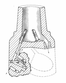
Positioning watercourses so the drilling fluid is directed onto the Roller Cone Drill Bit cutters has long been a standard design. The primary force of the fluid stream impinges upon the teeth to remove any adhering material, commonly termed Bit Balling. A portion of the energy in the stream reaches the bottom with enough capacity to sweep loose cuttings off the bottom and into the upward-moving annulus stream. Field tests have established that a relatively large portion of the stream must impinge on the outermost rows of cutter teeth, which are most prone” to ball up.
Excessive fluid velocity directed at the cone structure would severely erode the cutter shell and teeth. Therefore, the nozzle size, or throat, of the conventional bit must be compromised for maximum hole cleaning and minimum cone erosion. Nozzle sizes that result in velocities from 100-125 feet per second are generally used. Since these low fluid velocities are often inefficient for proper hole cleaning, bits with conventional watercourses are rapidly becoming rare. Their principal use now is in large bit sizes or in cheap bits for shallow, soft drilling.
Jet Nozzles Watercourses.
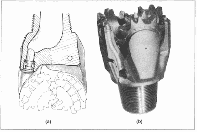
The principle of bottom-hole jetting to improve the Roller cone bit performance is not new. For years, Drilling engineers have known that the quick removal of cuttings from the bottom of the hole is essential for the best bit performance (Also check: PDC bit performance). Only in recent years has large-capacity, adequately powered mud pumps become general enough to warrant developing high-velocity jet bits. When mud pumps are small or have a limited power supply, the mud stream must be directed on the rock bit cutters to keep them properly cleaned. With adequate pump pressure, however, mud jets directed at the bottom of the hole will quickly lift the cuttings and create sufficient turbulence around the bit to clean the cutter teeth properly (see Fig.1).
One problem in directing the mud stream through the bit body and around the cutters outside in a jet bit is preventing washouts due to fluid erosion. A high-velocity, accelerating mud stream containing solids will erode the steel body if an eddy is created. To prevent washouts, all changes in the direction of the mud must be gradual; mud passageways must be streamlined; mud acceleration must be gradually increased, and nozzles made of a material such as tungsten carbide must be used at the watercourse exits to protect against excessive erosion since mud reaches its highest velocity at these points.
Most common Nozzle jets are made of tungsten carbide to minimize erosion. Since no single jet size is optimum for all conditions, jets must be designed to be easily replaced with a Nozzle jet of a different diameter. Jet sizes are generally recorded in thirty seconds of an inch and may range from small jets, such as 5/32, to very large sizes, such as 32/32.
Jet Nozzles Installation In Drilling Bits
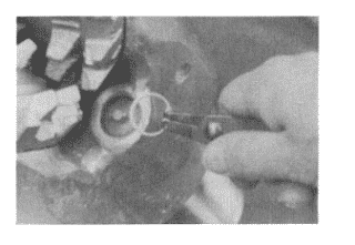
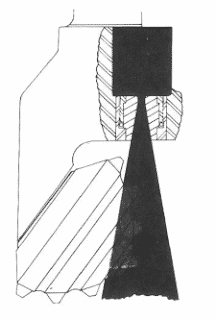
Nozzles Jets are secured in the drill bit in several manners, depending on the manufacturer. A common procedure is with a compressible lock ring. Fig. 2 illustrates a nozzle jet being installed with a lock spring.
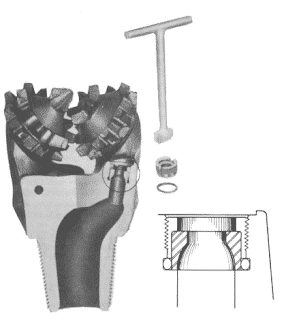
Another common Roller Cone Bit Jet Installation procedure utilizes threaded flow nozzles that are easy to remove and replace. A single nozzle wrench is needed for removal or installation, as shown in Fig.3. Nozzle retention is ensured through a compressed a-ring that acts as a shake-proof elastic stop nut above the nozzle and retainer. Fluid pressure on this a-ring during drilling locks the nozzle and retainer.
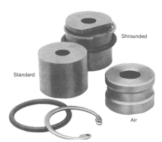
Technological advancements in Roller Cone bit design have increased bit life to the point where surface fluid erosion of the nozzle exposed to the wellbore becomes an important consideration. This is particularly true when retainer rings are used as the locking mechanism. To minimize ring wear, a shrouded nozzle similar to that shown in Fig.4 may be used. Shrouded nozzles have applications when drilling fluids contain relatively large amounts of abrasive materials when drilling in soft formations where the rock is close to the nozzle face, causing a potential balled-up condition, and when excessive fluid turbulence is experienced resulting from exceptionally high nozzle velocity. However, shrouded nozzles are more difficult to install.
Although most common jet Nozzles bits use three nozzles on the outer diameter of the bit, recent advancements have shown that including a fourth nozzle in the center of the bit is an advantage. The “center” nozzle helps clean the “dead” spot in the center area. Also, it aids in cone cleaning to a certain degree (see Fig.5). Bit manufacturers claim that a 15-17% increase in Penetration Rate (ROP) may be gained with the center-jet bit, particularly in soft, gummy formations.
Compressed air or gas is often the circulating fluid on regular or jet Nozzle circulation bits. Although air or gas generally will drastically increase penetration rates more than water or mud, they do not effectively cool and lubricate the bit and liquid media. As a result, bits manufactured for air or gas circulation have special passageways from the bit bore to the bearings through which a portion of the air or gas is diverted to keep the bearings cool and purged of dust, grit, or cuttings. From the special passageways to the bearings, the air or gas passes through several strategically located points or holes in the bearing journal, flows through the bearing structure, and exhausts at the shirttail and gauge of the cutter to flow up the annulus (see Fig. 6)