Example On The Drill String Drag Calculations
Given:
Well bore
- 9-5/8” 40# casing at 5000 ft
- Total Depth = 10,000 ft
- Hole Size = 8-1/2”
- Kick off Point = 5000 ft
- Build Rate = 10 deg/100 ft
- End of Build at = 5600 ft
- Tangent Section = 5600 to 10,000
- Inclination across tangent section = 60 deg
- Azimuth = 0 deg north (surface to 5000 ft)
- Azimuth is changed at the rate of 5 deg / 100 ft from 5000 ft to 5600 ft
- Azimuth = 30 deg from 5600 ft to 10,000 ft
- Mud Weight = 90 pcf
- Coefficient of friction = 0.25 in open hole and 0.2 in casing.
Drill String
- Drill pipe 5” OD, 5.276”ID, 19.5# normal weight 20.89# adjusted weight
- Drill Collars 7” OD, 2.25” ID, 117.42#, 400 ft long
With the drill string at bottom, calculate:
- The tension at surface required to move the drill string up hole
- Total drag force when moving string up hole
- The hook load when the string is off bottom and not moving
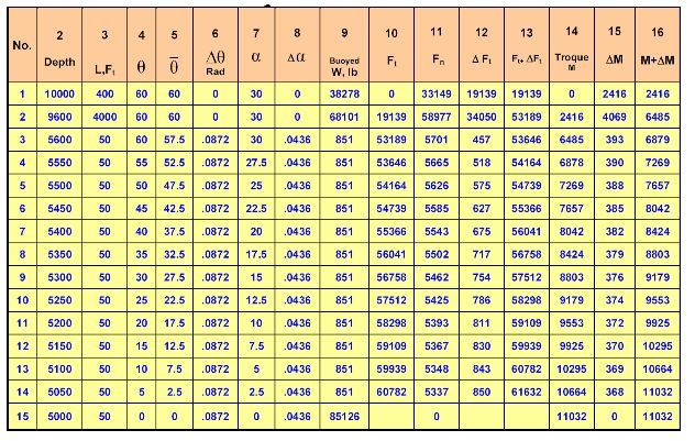
The first step is to divide the drill string into small elements from bottom to top as shown in below Table. The drill collars are considered as one element since there is no change in inclination or azimuth across them. The drill pipe in the tangent section from 9600’ – 5600’ is also taken as one element for the same reason. The drill pipe in the curved section from 5600 to 5000 is divided into twelve 50-ft elements because the inclination and azimuth change across the curved section. The last element is the vertical section from 5000’ to surface. The entries in the columns are defined as follows:
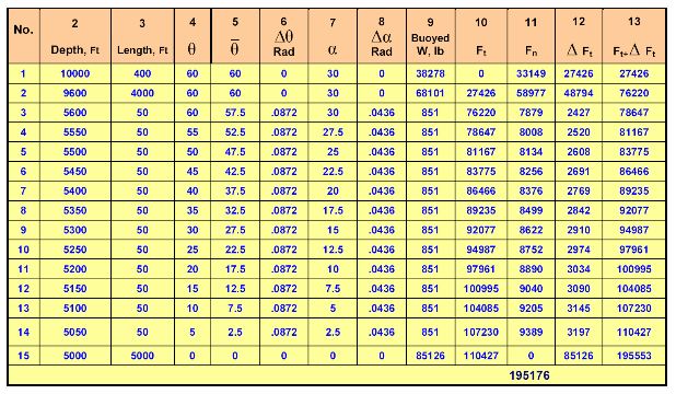
Column # 1: element sequence number
Column # 2: depth of the bottom of the element
Column # 3: element length in feet
Column # 4: angle of inclination in degrees at the bottom of the element
Column # 5: average angle of inclination across the element, or angle at bottom of element plus angle at top of element divided by 2.
Column # 6: change in angle of inclination across the element in radians, or angle at bottom of element minus angle at top of element. Multiply answer by
0.0174 to convert from degrees to radians.
Column # 7: azimuth at bottom of element in degrees.
Column # 8: change in azimuth in radians, or azimuth at bottom minus azimuth at top multiplied by 0.0174.
Column # 9: buoyed weight of the element which is the weight in air times the
buoyancy factor. For drill pipe use the actual or adjusted weight per
foot.
Column # 10: tension force Ft at the bottom of the element. In this case since the drill string is off bottom Ft = 0 for element # 1. If the string is on bottom then Ft is a compressive force equal to the weight on bit.
Column # 11: normal force Fn calculated by using Eq (32)

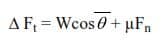
Column # 12: ΔFt calculated by below Eq.
Column # 13: tension at the top of the element and is equal to the value of Column # 11 plus the value of Column # 12.
Calculations for Element # 1
Column # 1: Element #1 consists of the entire drill collars which lie across the tangent section.
Column # 2: Depth at the bottom of drill collars is 10000 ft.
Column # 3: Length of drill collars is 400 ft.
Column # 4: Inclination at bottom of drill collars is 60 deg.
Column # 5: Average inclination is 60 deg because it is across tangent section, i.e. inclination at bottom of drill collars is same as at top.
Column # 6: Change in inclination in zero 60-60=0
Column # 7: Azimuth at bottom of drill collars is 30 deg.
Column # 8: Change in azimuth is zero because azimuths at top and bottom of drill collars are the same.
Column # 9: buoyed weight of drill collars Buoyancy factor = 490-90 /49 = 0.815 W = 400 x 117.42 x 0.815 = 38278 lb
Column # 10: The tension at the bottom of the drill collars is zero because the drill string is off bottom.
Column # 11: The normal force Fn is calculated by this Eq
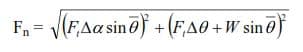
Fn = 33149 lb
Column # 12: Δ F is calculated by above Eq
ΔFt = Wcosθ + µFn = 38278 cos60 + 0.25 x 33149 = 27426 lb
Column # 13:
Ft+ Δ Ft = 0 + 27426 = 27426 lb
This is the tension at the top of the drill collars which is equal to the tension Ft
at the bottom of element # 2
Calculations for Element # 2
at the bottom of element # 2
Column # 1: This element is the bottom 4000 ft of 5” DP across the tangent section.
Column # 2: Depth of bottom end is at 9600 ft.
Column # 3: Length is 4000 ft.
Column # 4: Inclination angle across tangent section is 60 deg.
Column # 5: Average inclination angle is 60 deg.
Column # 6: No change in inclination angle.
Column # 7: Azimuth is constant at 60 deg.
Column # 8: No change in azimuth, zero
Column # 9: Weight of DP is, W = 4000 x 20.89 x 0.815 = 68101 lb
Column # 10: This is the tension at the bottom of the element which is equal to the tension at the top of the previous element.
Column # 11: The normal force is from above Eq
Fn = 58977 lb
Column # 12: Δ F from Eq
Δ Ft = Wcosθ + µFn
Δ Ft = 68101 x cos60 + 0.25 x 58977 = 48794 lb
Column # 13: Tension at top of element is
Ft + Δ F = 27426 + 48794 = 76220 lb
Calculations for Element # 3
Column # 1: This is a 50-ft element of 5” DP at the bottom of the build section. The inclination angle at the lower end is 60 deg and at the upper end is 55 deg (build rate of 10 deg/100 or 5 deg per 50 ft). The azimuth at lower end is 30 deg N and at upper end is 27.5 deg N (azimuth is changed at rate of 5 deg/100 ft or 2.5 deg per 50 ft.)
Column # 2: Depth of lower end of element is 5600’ – end of tangent section.
Column # 3: length of element is 50 ft.
Column # 4: Inclination at bottom of element is 60 deg. Inclination at top of element is 55 deg.
Column # 5: Average inclination is
60+55/2 = 57.5 deg
Column # 6: Change in inclination angle is
60-55 = 5 degrees
5 x 0.01744 = 0.0872 radians
Column # 7: Azimuth at lower end is 30 deg.
Column # 8:
Change in azimuth is Azimuth at lower end – Azimuth at upper end
30 – 27.5 = 2.5 deg
2.5 x 0.01744 = 0.0436 radians
Column # 9:
W = 50 x 20.89 x 0.815 = 851 lb
Column # 10: Tension at bottom of element is equal to tension at top of previous element 76220 lb.
Column # 11:
Fn = 7879 lb
Column # 12:
Δ Ft = 851cos57.5 + 0.25 x 7879 = 2427 lb
Column # 13: Tension at top of element is
2427 + 76220 = 78647 lb
Calculations for elements 4 through 14 are done in the same manner.
Calculations for Element # 15
Column # 1: This is the last element. It is the DP in the vertical section from surface to the kick off point at 5000 ft.
Column # 2: Depth of lower end is at 5000 ft.
Column # 3: Length is 5000 ft.
Columns # 4 through 8: All values are zero because the pipe is vertical
Column # 9:
W = 5000 x 20.89 x 0.815 = 85126 lb
Column # 10: Tension at bottom end is 110427 lb
Column # 11: The normal force is zero because the pipe is vertical and is not lying on the hole.
Fn = 0
Column # 12:
ΔFt= 85126 x cos0 + 0.25 x 0 = 85126 x 1.0 + 0 = 85126 lb
Column # 13: Tension at the surface is
85126 + 110427 = 195,553 lb
Therefore, it requires a pull of 195,553 lb to move the pipe up hole. The Landmark torque and drag software (WELL PLAN) gave a value of 193, 500 lb.
b) The total drag force is the sum of all drag forces generated by all elements, or F μ (Total Drag Force)
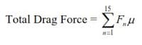
This is the sum of all normal forces times the friction coefficient. The sum of all normal forces is obtained by adding all values of F in Col # 11 which is 195176 lb. Therefore,
Total Drag = 195176 x 0.25 = 48794 lb
c) The hook load when the pipe is static is
195553 – 48794 = 146,759 lb
The hook load is also equal to
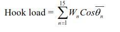
Example On The Drilling Torque Calculation
Given:
Well bore
- 9-5/8” 40# casing at 5000 ft,
- Total Depth = 10,000 ft,
- Hole Size = 8-1/2”,
- Kick off Point = 5000 ft
- Build Rate = 10 deg/100 ft,
- End of Build at = 5600 ft,
- Tangent Section = 5600 to 10,000
- Inclination across tangent section = 60 deg,
- Azimuth = 0 deg north (surface to 5000 ft)
- Azimuth is changed at the rate of 5 deg / 100 ft from 5000 ft to 5600 ft
- Azimuth = 30 deg from 5600 ft to 10,000 ft
- Mud Weight = 90 pcf, Coefficient of friction = 0.25 in open hole and 0.2 in casing.
Drill String
- Drill pipe 5” OD, 5.276”ID, 19.5# normal weight 20.89# adjusted weight
- Drill Collars 7” OD, 2.25” ID, 117.42#, 400 ft long
With the drill string at bottom, calculate:
- Calculate the surface torque required to turn the string off bottom with no tripping.
- Calculate the torque while drilling. Use a bit torque of 2000 ft-lb. Drill pipe tool joint OD is 6.625 in.
Solution
The drill string is divided into small elements as was done for calculating drag.
Calculations are tabulated in below Table. The data in columns 10, 11 and 13 are calculated in the same manner as was done for the drag calculations in the previous example.
For drag calculations, the tension increment Δ F in column 12 is calculated by below Eq.

where µFn in the incremental drag caused by moving the element up hole. However, since in this example there is no tripping pipe, the drag increment due to uphole or downhole movement is zero, and the tension increment Δ Ft is

Column 14 is the torque at the bottom of the element. If the string is off bottom the torque is zero. For the case of drilling the torque is the bit torque which have to be estimated. The torque increment Δ M in Column 15 is the torque resistance exerted by the element and is calculated by using below Eq. ΔM = FnRµ
Column 16 is the torque at the top of the element which is M + Δ M. The torque at the top of the element ( M + Δ M ) is the torque at the bottom of the next element. The calculations are repeated for all elements to the surface.
Drilling Torque Calculation for Element # 1
Columns 2 through 11 are calculated as in the previous example.
Column # 12. is calculated by

Δ Ft = 38278 x cos60 = 19139 lb
Column # 14. The torque at bottom of element in this case is zero because the drill string is off bottom (no bit torque)
Column # 15. Torque increment Δ M Δ M = Fnµr
Drill Collar OD
r = —————– = 7/2 = 3.5″ = 0.2916 ft
2
Δ M = 33149 x 0.25 x 0.2916 = 2416 ft-lb
Column # 16. Torque at top of element #1 is M + Δ M = 0 + 2416 ft-lb = 2416 ft-lb
Drilling Torque Calculation for element # 2
Columns # 10 and 11 are calculated in same manner as in the drag example
Column # 12: ΔF = 68101 cos 60 = 34050 lb
Column # 14: Torque at bottom of element # 2 is same as torque at top of element # 1 or 2416 ft-lb
Column # 15: Δ M = Fnrµ
Tool Joint OD
r = —————- = 6.625/2 = 3.312″ = 0.276 ft
2
Δ M = 58977 x 0.276 x 0.25 = 4069 ft – lb
Column # 16: Torque at top of element # 2 is Δ M + M = 4069 + 2416 = 6485 ft-lb
Calculations for elements 3 through 14 are done in the same manner as for element # 2.
Drilling Torque Calculation for element # 15
Since the inclination angle is zero, the normal force F is zero and the torque increment, Δ M is also zero. In other words, drill pipe in vertical hole can be turned with no or very little torque. So the torque at top of element # 15 (the surface) is equal to torque at top of element #14 which is 11032 ft-lb
b) If the bit torque is 2000 ft-lb then the torque at surface is Torque = 11032 + 2000 = 13032 ft-lb
It can be seen from the above example problems that the calculation of torque and drag consumes large amount of time and is best done by using computer software.