A vertical cuttings dryer treats the wet solids discharged by primary solids-control equipment, recovering part of the fluid that would otherwise leave with them. Assessing it requires more than a photograph of apparently dry cuttings. The separated solids still contain liquid, and the recovered liquid can carry fine drilled solids. Both output streams need attention. [1, pp. 406–412]
The useful questions are straightforward: what material reaches the dryer, how does the particular machine separate it, what does the reported retention number mean, and how much recovered fluid is ultimately suitable for return? This article explains those questions without treating a historical product’s capacity or discharge target as a universal operating limit.
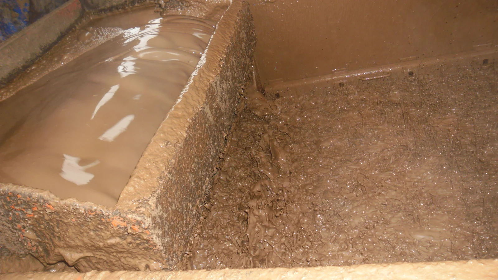


Where a vertical cuttings dryer fits in the process
Primary shakers separate a large part of the drilled solids from the returning fluid. The solids discharged from that stage carry liquid on and between the particles. Secondary drying treats this wet discard stream to recover more fluid before the remaining solids enter their designated handling route. It does not remove the need for effective primary separation. [1, pp. 406–412] [3, pp. 113–115]
A vertical cuttings dryer therefore belongs in a complete material-handling arrangement: feed delivery, the dryer, a solids outlet, and a separate liquid collection and conditioning route. The Baker manual illustrates cuttings delivery from shakers, collection below the dryer, and subsequent centrifuging of recovered liquid. Its arrangement is useful for understanding the relationships, not as a site installation drawing. [2, pp. 14-49–14-50]
The solids-control equipment overview covers the broader system. Here the focus is the additional recovery opportunity in the solids that have already left the main fluid-processing stream. A dryer assessment must keep that boundary visible so recovery is not confused with treatment of the entire circulating flow.
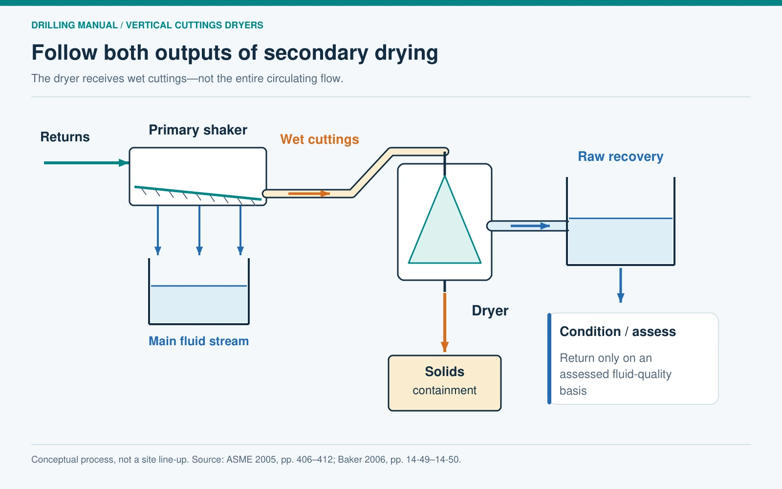
How a vertical cuttings dryer separates the feed
In the screened dryer arrangements described in the supplied books, centrifugal action drives liquid toward and through a screen while larger retained solids progress to a separate outlet. The screen is a physical separation boundary. The liquid collected outside it is a recovered stream, not automatically pure base fluid. The ASME handbook describes several horizontal and vertical configurations, with different ways of moving solids. [1, pp. 406–409]
One specific historical example makes the mechanics clear. Baker Hughes’ 2006 reference manual describes the Typhoon with a rotating cone carrying spiral flights and a fixed screen or basket. Cuttings contact that screen, liquid drains into collection, and solids leave below. The original diagram in this article uses that stated arrangement and labels it explicitly. It should not be read as a claim that every vertical cuttings dryer has a stationary basket. [2, p. 14-49]
This distinction matters when reading a proposal or drawing. Identify which component rotates, how the retained solids travel, where liquid crosses the screen, and how the two outlets remain separate. A generic arrow labelled “centrifugal force” cannot establish those details for an unfamiliar machine.
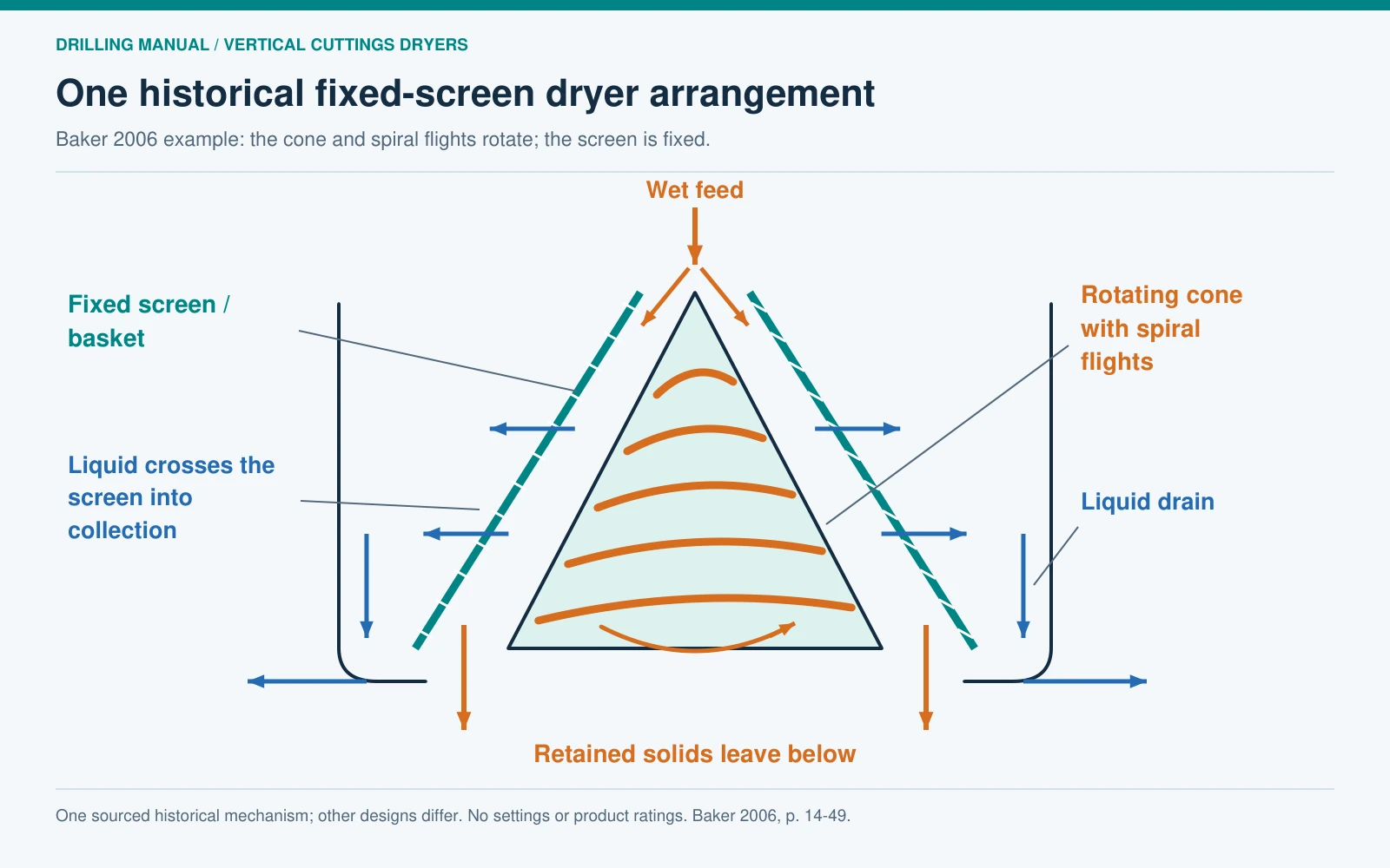
Dryer, shaker and decanter: different jobs and mechanisms
The word centrifuge can describe more than one arrangement. A screened cuttings dryer and a solid-bowl decanter both use rotation, but their separation paths differ. The decanter described in the ASME handbook accelerates sedimentation in a rotating bowl and uses a differential-speed scroll to transport the settled solids. Its principal separation boundary is not a liquid-permeable screen. [4, pp. 303–305]
| Equipment | Feed considered here | Principal separation feature | Place in this discussion |
|---|---|---|---|
| Primary shale shaker | Returning drilling fluid and cuttings | Fluid passes a vibrating screen; retained cuttings travel off it | Provides the wet solids stream that may receive secondary treatment |
| Screened vertical cuttings dryer | Wet cuttings discard | Centrifugal action assists liquid passage through a screen | Recovers fluid remaining with the solids |
| Solid-bowl decanter | A fluid stream containing separable solids | Accelerated settling, with scroll transport of the settled material | Can form part of recovered-fluid conditioning |
The comparison follows the three mechanisms described in the books. [1, pp. 406–410] [3, pp. 113–115] [4, pp. 303–305] See the oilfield centrifuge guide for the broader centrifuge discussion and the mud cleaner guide for another, different combination of solids-control stages.
Why the feed matters as much as the machine label
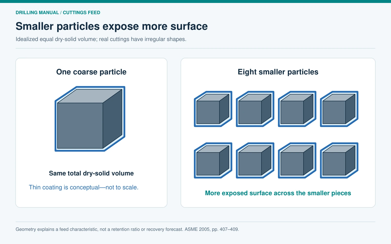
The vertical cuttings dryer feed is not a steady stream of identical particles. Its cuttings size, liquid content and delivery rate can change. Finer particles present more surface area for a given amount of solids and can be harder to bring to a low liquid retention. The ASME discussion also identifies differences in screen geometry, residence time and solids-transport arrangements among dryer designs. These are reasons to evaluate a stated feed condition rather than transfer a performance number from an unrelated application. [1, pp. 407–409]
A vertical cuttings dryer system must also accommodate variation between the shakers and its inlet. The book describes feed-handling difficulties when drilling conditions change, and when whole drilling fluid enters the cuttings route during disturbances at primary separation. Average throughput alone does not describe such events. Collection, conveying and downstream handling are part of the assessment. [1, pp. 409–412]
The particle sketch illustrates a surface-area principle, not a formula for retention. Real cuttings have irregular shapes and changing coatings. It would be unjustified to turn that sketch into a predicted recovery percentage, or to prescribe one speed, screen or feed setting for every mud and formation.


Vertical cuttings dryer retention: define the basis
In the ASME waste-management discussion, retention on cuttings is expressed as base-oil mass relative to the mass of wet cuttings. That denominator matters. Oil content, total liquid content, the fraction of incoming oil recovered, and the reduction in discard mass are different quantities. A report should state what was measured instead of presenting an unexplained percentage beside the word “recovery.” [1, pp. 406–410]
For the defined oil-on-wet-cuttings basis:
Oil retention (%) = oil mass remaining with the discharged cuttings ÷ wet discharged-cuttings mass × 100.
This is a mass fraction. A volume-based fluid test or a dry-solids denominator cannot be substituted without the appropriate conversion and a clear definition. Nor does a lower oil-retention result identify the destination or quality of the liquid removed. Those are separate parts of the material balance.
Keep the vertical cuttings dryer feed and output samples tied to the same assessment period and record the test basis. This is an accounting requirement for a meaningful comparison, not a sampling procedure. A good vertical cuttings dryer report makes the numerator, denominator and material boundary explicit.
An original example: follow solids, oil and water separately
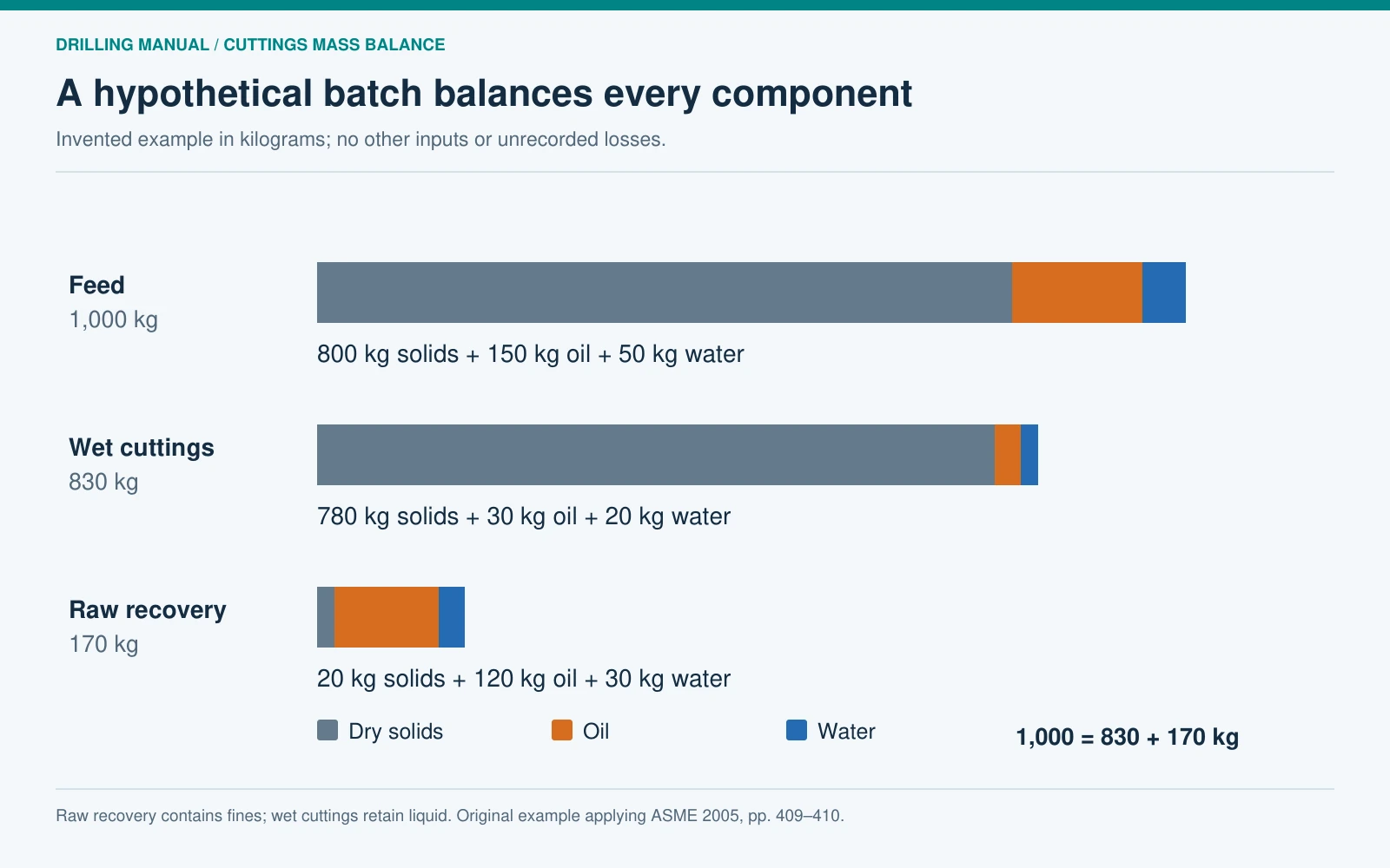
Consider an invented batch containing 1,000 kg of wet cuttings: 800 kg dry solids, 150 kg oil and 50 kg water. Assume the vertical cuttings dryer produces the two streams below, with no unrecorded losses or additional inputs. These numbers are an accounting illustration, not measured performance, a vendor specification or a treatment target.
| Component | Feed | Wet cuttings discharged | Raw recovered stream |
|---|---|---|---|
| Dry solids | 800 kg | 780 kg | 20 kg |
| Oil | 150 kg | 30 kg | 120 kg |
| Water | 50 kg | 20 kg | 30 kg |
| Total | 1,000 kg | 830 kg | 170 kg |
Each component balances, as does the total: 1,000 = 830 + 170 kg. The 20 kg of solids in the recovered stream represent fine material carried with the liquid. That detail reflects the book’s warning that dryer effluent can contain low-gravity solids; it is not a forecast of the amount a real machine will pass. [1, pp. 409–410]
Calling the entire 170 kg “recovered oil” would be wrong. It contains 120 kg oil, 30 kg water and 20 kg solids. Similarly, the 830 kg cuttings discharge is not dry mineral matter: it includes 50 kg of liquid. Both descriptions must preserve the component accounting.
Three useful results, three different denominators
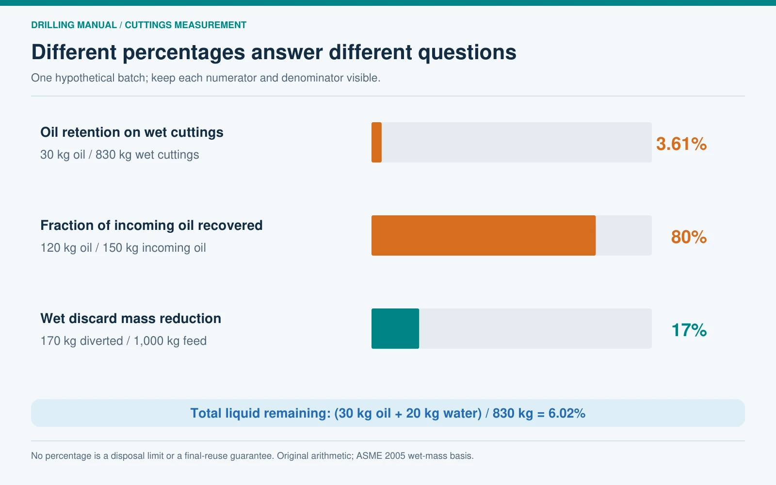
The same hypothetical batch gives three distinct performance measures. None should be relabelled as another:
| Measure | Calculation | Result | What it describes |
|---|---|---|---|
| Oil retention on wet discharged cuttings | 30 ÷ 830 × 100 | 3.61% | Oil remaining in the solids discharge on the stated wet-mass basis |
| Fraction of incoming oil recovered | 120 ÷ 150 × 100 | 80% | Incoming oil reaching the raw recovery stream |
| Wet discard mass reduction across this stage | (1,000 − 830) ÷ 1,000 × 100 | 17% | Mass diverted from the initial wet-cuttings stream |
Total liquid in the discharged cuttings is 50 ÷ 830, or 6.02% by mass. That is greater than its 3.61% oil content because water is also present. The result does not contradict itself; the quantities have different numerators.
The 17% reduction describes only this stage and boundary. If subsequent conditioning rejects some recovered liquid with fines, the overall waste and reuse figures change. The ASME handbook specifically notes that removing fines from dryer effluent can lose additional fluid. Thus 80% raw oil recovery in this imagined example is not an 80% final-reuse guarantee. [1, pp. 409–410]
Judge the recovered fluid and the solids outlet separately
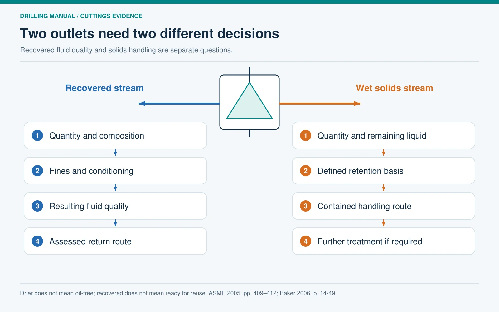
The recovered stream from a vertical cuttings dryer can require further solids removal before it is suitable for return to the drilling-fluid system. The source describes fine screening or centrifuging for that purpose, and Baker’s example also sends recovered liquid through a centrifuging stage. The decision concerns the resulting fluid quality and the receiving system, not simply whether liquid has been recovered. [1, pp. 409–410] [2, pp. 14-49–14-50]
The vertical cuttings dryer solids outlet has a different question: what liquid remains, in what quantity, and what handling route is appropriate for that material? “Drier” is a comparative description, not proof of zero oil or permission for disposal. The historical handbook includes specific environmental targets and disposal arrangements; none is adopted here as a current or universal requirement.
Keep these two decisions separate in the process drawing. The recovered stream goes to collection, assessment and any required conditioning. The wet solids go to their designated containment and treatment route. Neither outlet should disappear into an arrow labelled “clean” without supporting evidence. The mud circulating-system guide provides context for the system that may receive suitably conditioned fluid.

What a credible vertical cuttings dryer assessment records
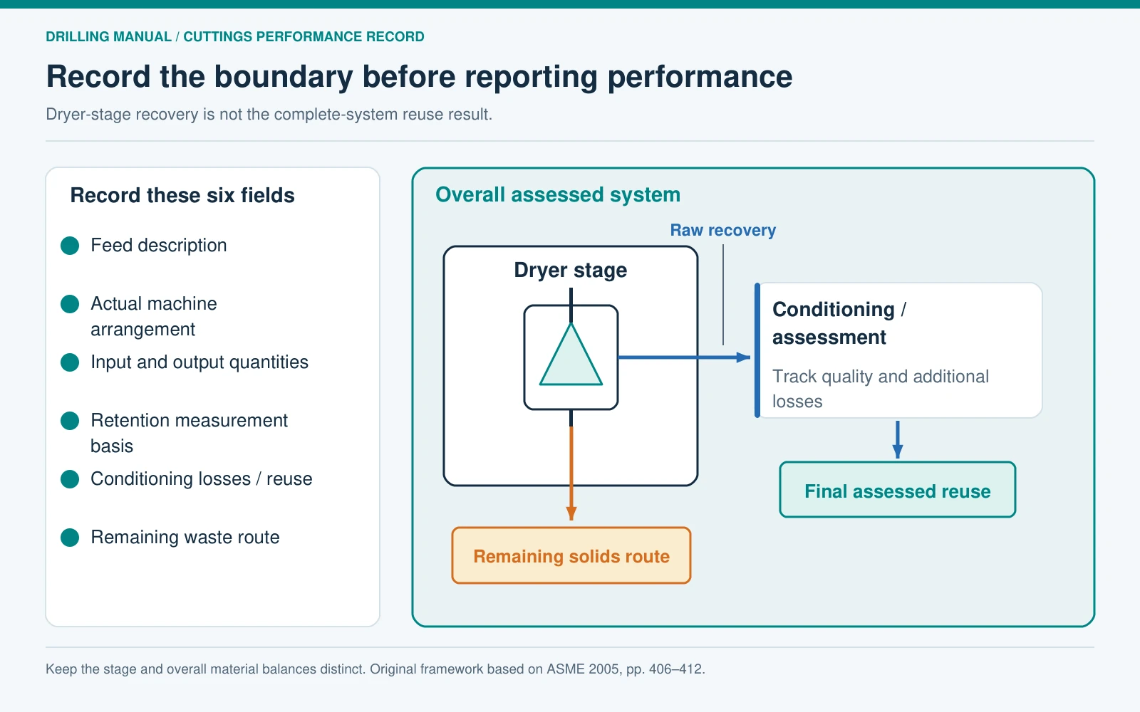
A useful assessment connects the machine to the material balance and its surrounding equipment. The following record applies the book’s discussion of feed variation, recovery, fines and system integration. It is not a commissioning checklist. [1, pp. 406–412]
- Feed: identify the fluid system, cuttings characteristics, delivered quantity and relevant variation.
- Machine: identify the actual screen and transport arrangement; do not infer its mechanics from another model.
- Output measurements: record both stream quantities and the basis of retained-liquid measurements.
- Recovered-fluid route: identify further conditioning, resulting quality and any additional losses.
- Solids route: record remaining liquid and the designated handling destination.
- Boundary: distinguish dryer-only recovery from the complete system’s final reuse and waste results.
Those distinctions let a vertical cuttings dryer be assessed for the job it actually performs: additional separation from a variable wet-cuttings stream. They also make it possible to recognize a useful recovery result without overstating fluid quality, final waste reduction or disposal acceptability.
Frequently asked questions
Is a vertical cuttings dryer the same as a decanter centrifuge?
No. The screened dryer discussed here assists liquid passage through a screen while retained solids leave separately. A solid-bowl decanter separates by accelerated sedimentation and transports settled solids with a scroll. Both use rotation, but their internal separation paths differ. [1, pp. 406–409] [4, pp. 303–305]
Does the dryer remove every trace of liquid?
No. Secondary drying reduces the liquid carried with the solids; it does not establish zero retained fluid. Report the measured retention on its stated basis rather than using “dry” as a numerical result. [1, pp. 406–410]
Can recovered liquid return directly to the active system?
Do not assume so from the recovery figure. The source describes fine solids in dryer effluent and further separation before appropriate return. The receiving-fluid requirements and the actual recovered-stream quality still need assessment. [1, pp. 409–410] [2, p. 14-49]
Is oil retention the same as oil recovery efficiency?
No. Retention on the stated wet-cuttings basis compares remaining oil with wet discharged solids. Oil recovery compares oil collected with oil entering the assessed stage. The example produces 3.61% retention and 80% raw oil recovery without any contradiction.
Can one retention target describe every application?
No universal target follows from these sources. Feed characteristics and dryer arrangements vary, and a historical result does not establish another installation’s performance or present disposal requirements. Specify the measurement basis and applicable project requirements. [1, pp. 406–412]
Can secondary drying replace primary solids control?
That is not its role in the process described here. The dryer receives wet solids already discharged from primary equipment. Effective primary separation and consistent delivery remain part of the complete arrangement. [1, pp. 406–412] [3, pp. 113–115]
References
- Piper, William; Harvey, Tim; and Mehta, Hemu. ‘Waste Management,’ Chapter 16 in Drilling Fluids Processing Handbook. ASME Petroleum Division-sponsored handbook. Gulf Professional Publishing / Elsevier, 2005. ISBN 0-7506-7775-9. Printed pages: 406–412. PDF pages in the edition consulted: 433–439.
- Baker Hughes Drilling Fluids. Drilling Fluids Reference Manual, revision 2006. Chapter 14, ‘Fluids Environmental Services,’ ‘Cuttings Dryer’ and ‘Typical Cuttings Dryer Arrangements.’ Printed pages: 14-49–14-50. PDF pages in the edition consulted: 711–712.
- ‘Shale Shakers,’ Chapter 7 in Drilling Fluids Processing Handbook. ASME Petroleum Division-sponsored handbook. Gulf Professional Publishing / Elsevier, 2005. Printed pages: 113–115. PDF pages in the edition consulted: 140–142.
- Bouse, Eugene. ‘Centrifuges,’ Chapter 13 in Drilling Fluids Processing Handbook. ASME Petroleum Division-sponsored handbook. Gulf Professional Publishing / Elsevier, 2005. Printed pages: 303–305. PDF pages in the edition consulted: 330–332.