The use of screens (Shaker Screen) to remove drilled solids from mud uses only one characteristic of solids particles -their size. Solids control devices that speed up drilled solids’ settling process by applying centrifugal force take advantage of two factors – particle size and particle density. Hydrocyclones (Desanders & Desilters) and centrifuges in oilfields rely on this principle.
Stoke’s Law
Centrifuges utilize Stoke’s Law in their operation. Stoke’s Law governs the settling velocity of particles in a liquid. We can state this relationship in its simplest form:
Vs = A (ds2)(Ds – Di)/4.5 KU,
Where:
- Vs = the terminal settling velocity of the particle
- A = the acceleration applied to the particle
- ds = the diameter of the particle
- Ds = the density of the solid particle
- Di = the density of the liquid
- K = a dimensional constant
- U = the viscosity of the liquid
This equation indicates that larger particles (of the same density) will settle more rapidly than smaller ones, that high-density solids will settle more quickly than low-density ones, and that high acceleration and low viscosity speed up the settling rate.
Principles Of Performance
The key difference between oilfield centrifuges and previously discussed solids control devices is the operating capacity and duration. Unlike shale shakers, cyclones, and mud cleaners, which operate continuously on the full mud circulation volume, centrifuges operate intermittently on a small fraction of the circulating volume (usually 5 -10%). The classic use of centrifuges is to remove colloidal-size solids from weighted water-base muds to salvage barite and avoid excessive viscosity, which can result from high colloidal content. We can use the decanting, solid bowl centrifuge and perforated cylinder centrifuge in this application.
There are mainly two types of oilfield centrifuge:
- Decanting Centrifuge
- Solid Bowl Centrifuge
Decanting Oilfield Centrifuges
Decanting centrifuges have earned their name because they can remove, or “decant”, free liquid from the separated solid particles and leave only adsorbed or “bound” water on the surface. The decanting centrifuge is the most common type in drilling applications.
Operating Principle:
The operating principle is that of Stoke’s Law, but unlike the cyclone, it is not fluid pressure but the rather mechanical rotation of the bowl which induces the centrifugal force required to accelerate the settling rate.
The Operating Principles of decanting centrifuge in an oilfield are as follows:
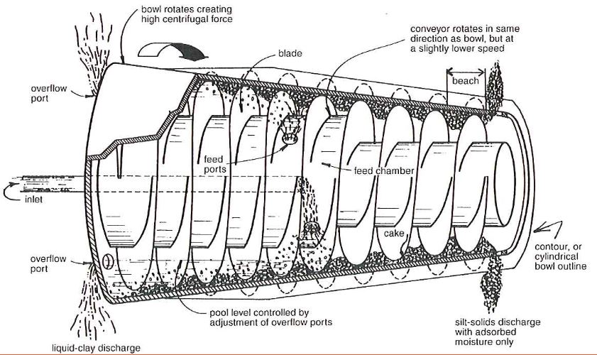
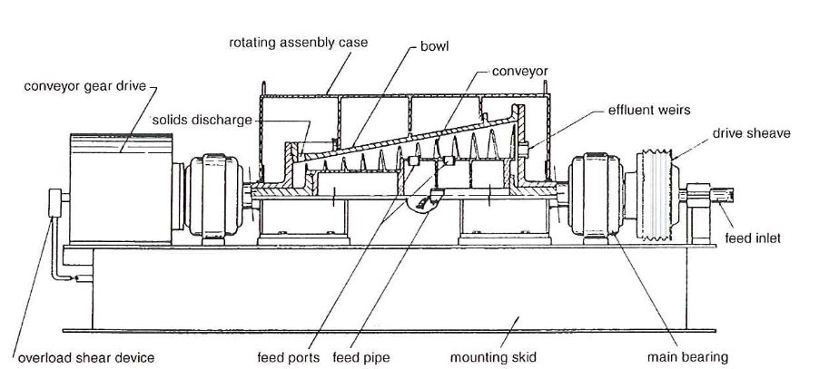
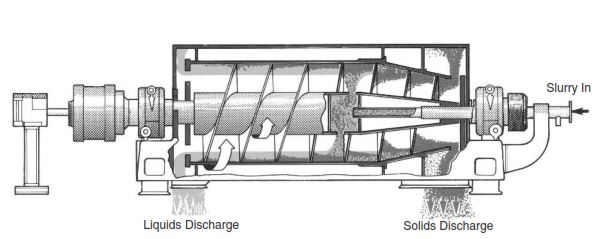
- A decanting centrifuge consists of a conveyor screw inside a solid bowl rotated at very high speeds (1500 – 3500 rpm).
- Usually, we dilute the mud with water and then pump it into the conveyor.
- As the conveyor rotates, it throws out the mud of the feed ports into the bowl.
- Centrifugal force pushes the heavy, coarse particles in the rotating mud against the wall of the bowl, where the scraping motion of the conveyor screw moves them toward and out the solids discharge port.
- The light, fine solids remain suspended in the pools between the conveyor flutes and are carried out in the overflow ports along with the liquid phase of the mud.
Operating Considerations
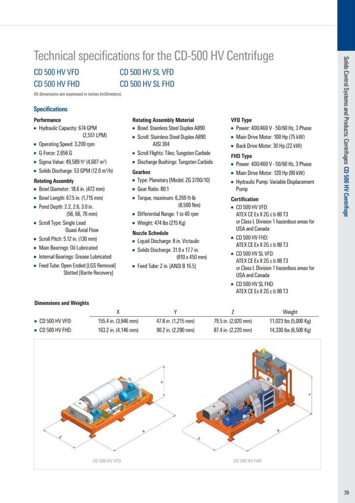
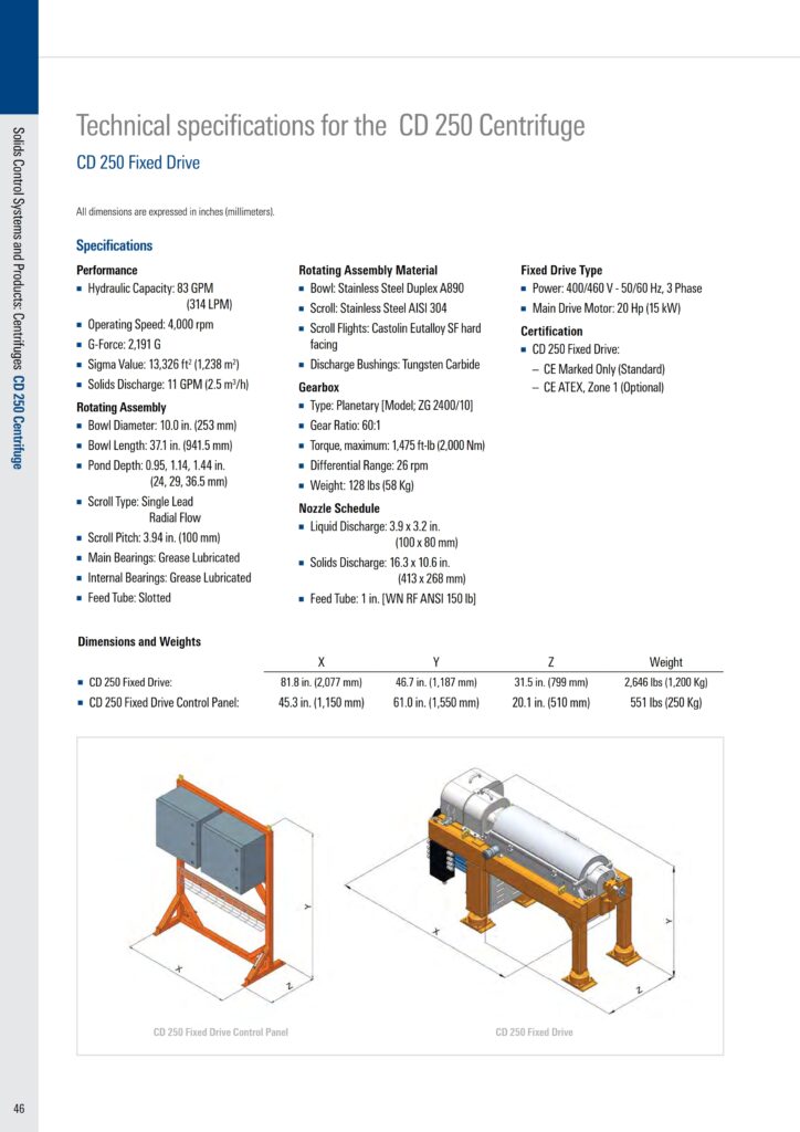
Bowl sizes in common centrifuge oilfield applications include 14″ x 20″, 14″ x 22″, and 18″ x 28″. Larger (24″ x 38″ and larger), high-capacity units are also available for special applications. Generally speaking, the larger the bowl, the greater the capacity at comparable efficiency.
In field operation, the decanting centrifuge is fired with housing over the bowl, liquid, and solids collection hoppers, skid, feed slurry pump, raw mud and dilution water connections, power source, meters, and controls.
Feed mud capacity rarely exceeds 25 GPM for the normal weighted mud application (more often 7 – 15 GPM), while total liquid throughput may be as high as 40 GPM (including dilution water). As mud weight increases, the raw mud feed rate will substantially decrease. To maintain satisfactory separation efficiency, we will need dilution water to compensate for increasing viscosity, generally associated with increasing mud weight.
Perforated Cylinder Oilfield Centrifuges
Perforated Cylinder Centrifuges operate somewhat differently but for the same ultimate purpose as decanters.
Centrifuge Operating Principle
- The perforated cylinder centrifuge consists of a perforated cylinder (or rotor) about 3′ long, revolving at about 2300 rpm, which is contained in an outer stationary cylindrical ease.
- A diluted feed of weighted mud is pumped into the stationary case tangential to the rotor.
- The unit separates the feed slurry into two streams of differing density and particle size distribution.
- Under centrifugal force, larger solids are concentrated against the annular wall for discharge at an underflow port.
- Finer solids pass through the multiple 1/2″ perforations to exit through the center shaft.
Oilfield Centrifuge Operating Considerations
We obviously can control flow into and out of the machine by positive displacement pumps. Two pumps are located at the feed end – one for raw mud and another for dilution water. A third pump controls the flow split and separation or cut by drawing fluid from the underflow port in the outer cylinder.
Raw feed mud capacity varies between 10 and 30 GPM, depending on mud weight and the desired separation. In addition, we generally held dilution water to about 70% of the raw mud feed rate so that we can reduce feed viscosity. Ordinarily, a volume of 60 – 90% of the total feed mud and dilution water reports to the underflow containing the coarser particle size distribution.
Unlike the decanter, which produces one wet and one dry fraction, both slurry streams exiting the perforated cylinder centrifuge are wet and pumpable. For this reason, the perforated cylinder centrifuge only applies to weighted mud.
Applications
Viscosity
We can effectively control viscosity by discarding a relatively small amount of colloidal-size solids. Standard centrifuge applications in oilfields use their ability to make a very fine cut – on the order of 2 – 6 microns.
In this application, centrifuge operation is intermittent rather than continuous. This relates to the standard purpose of the centrifuge — to control viscosity by removal of colloidal size particles. Therefore, we should run centrifuges when viscosity reaches the operator-established maximum. In addition, we should stop it when viscosity reaches the established minimum.
We should establish the maximum and minimum limits as part of the overall mud program. Viscosity will normally creep up when centrifuges are shut down due to the size degradation of mud solids, hence the need for restarting the unit. We always should avoid over-centrifuging and under-centrifuging, as operation economics quickly disappear under these circumstances.
Prolonged use of a centrifuge, or “over-centrifuging”, may cause too great a viscosity reduction, contributing to high downhole fluid loss. Therefore, you must add back bentonite and chemicals to the mud system. Also, We can exactly calculate the amount of replacement bentonite from mass balance equations. Remeber, a good rule of thumb is to add about one sack of bentonite per hour of centrifuge operation. “Under-centrifuging” will not achieve the desired reduction in viscosity.
Weighted Water Based Drilling Mud
When treating weighted water-base muds, we are using centrifuges intermittently to process a small portion of the volume circulated from the well bore. That is to reduce the colloidal number and improve the mud’s flow properties.
To remove these solids, we shall discard the liquid fraction from the decanter (or the lighter slurry fraction from the perforated cylinder centrifuge). The sand-size and silt-size semi-dry solids fraction from the decanter (or the heavier slurry fraction from the perforated cylinder centrifuge) will return to the active system.
Centrifuge Closed Loop System In Oil & Gas
Other popular applications of centrifuges are to reduce overall solids content, reduce average particle size, and to reduce overall waste volume by “dewatering” the discharge from other solids control equipment. Environmental considerations may require special handling of the solid and/or liquid phase. As the disposal cost increases, the waste volume becomes a major component of overall well cost. Additional solids removal equipment — such as a decanting centrifuge — is often cost-effective due to minimized waste volume. (In addition, we will have a better control of drilling fluid properties, further reducing well cost.)
We already calling these systems “restricted discharge”, or “closed loop”. In unweighted applications, the centrifuge discharges the ultra-fine solids and returns the liquid effluent to the mud system. This reduces the fine solids build-up and dilution requirements. We should operate the centrifuge as needed to maintain desired LGS concentration, continuously if needed.
Benefits:
Large, high-capacity (100 – 250 GPM) decanting oilfield centrifuges are more preferrable for these applications because they can process larger volumes of both solids and liquids.
One system uses a decanting centrifuge to process the underflow from hydrocyclones. This variation dewaters the cone underflow, recovering the liquid phase and reducing disposal volume.
Other variations on this system include screening the underflow from the cones before feeding it to the centrifuge and installing two centrifuges. Each of these options increases the removal efficiency of the system.
The goal of closed-loop systems is to limit waste discharge to disposable solids and clear water. These systems combine high-performance shakers, hydrocyclones or mud cleaners, and centrifuges with enhanced solids removal and solids handling techniques.
We can accomplish enhanced solids removal with a chemical addition to “pre-treat” the fluid before screening or centrifugation. Pre-treatment can include pH adjustment, flocculation/coagulation, or similar treatment.
Solids handling techniques include cuttings washing to remove excess chlorides or residual oil, conveyors to discharge cuttings into sealable containers, transport to approved waste facilities, and incineration of waste products.
In addition to their primary goal, closed-loop systems minimize drilled solids remaining in the drilling fluid. This reduces dilution requirements, waste volume, and drilling problems. Therefore, closed-loop systems have many applications besides environmental ones — with KCl or other expensive muds, for example.
Multiple Oilfield Centrifuges
In general, we can use multiple centrifuges in parallel to increase flow capacity and mass solids removal in each of the special applications listed above. Other applications, such as weighted oil-base muds, also use multiple centrifuges, usually two, operated in series.
In this application, the first centrifuge processes the drilling fluid in the classic weighted mud operation — discarding the effluent and colloidal solids and returning the oversize solids to the active system. The effluent (normally discarded) is processed through a second centrifuge before discarding. The second centrifuge removes most of the remaining solids from the effluent and discards them. The effluent is then recovered and returned to the system.
From a solids removal efficiency standpoint, results have been inconclusive. The main reason to process weighted fluids through a centrifuge is to reduce viscosity by removing a portion of the ultra-fine solids. The second centrifuge returns some of these solids to the mud system with the effluent, thereby reducing the overall efficiency.
The benefit of this system comes from reduced discharge volume with weighted fluids. This has proven extremely effective in environmentally sensitive areas or whenever cuttings and liquid mud must be hauled from the location before disposal.
Placement Of Oilfield Centrifuges In Solid Control System
Usually, we install the centrifuge downstream from all other solids control equipment. Ideally, suction for a centrifuge mud feed would be taken from the same pit or compartment which receives the discharge from a mud cleaner or fine screen shaker with 150 – 200 mesh screens.
The centrifuge underflow (solids) should be discharged to a well-stirred spot in the pit for thorough mixing with whole mud before the solids can settle out in the bottom of the pit. This is especially important with a decanter, which discharges damp solids, and of lesser importance with a perforated cylinder centrifuge, which discharges a pumpable slurry.
With either type of machine, the underflow discharge should not be too close to the rig mud pump suction. The overflow (liquid/colloidal solids) gravity-feeds down a constantly sloping chute or pipe to waste. Sufficient working space should be provided for routine maintenance and operating adjustments to the centrifuge.
Operating Tips For Centrifuges In Oil & Gas
Oilfield centrifuges are relatively easy to operate, but they require special skills for repair and maintenance. Drilling rig maintenance of centrifuges is limited to routine unit lubrication. Although operating procedures will vary in detail from model to model, a few universal principles apply to virtually all centrifuges:
- If the solids underflow is to return to the system, locate the centrifuge so the underflow falls into a well-stirred spot.
- If the solids underflow is to be discarded, locate the machine so the underflow can be removed periodically. Direct the liquid overflow to a well-stirred spot.
- Do not locate the machine solids or liquid returns too close to the rig pump suction.
- Allow time and space for adequate mixing.
- Liquid effluent lines should have a constant downward slope.