Well planning in oil and gas is the process of turning a reservoir objective into a well that can be drilled, pressure-controlled, cased, evaluated, and ultimately completed. A workable plan must show not only where the well will go, but also why the proposed trajectory, casing seats, mud system, and rig can handle the anticipated conditions.
This article focuses on the engineering decisions behind a well plan: how to use offset-well evidence, account for uncertainty, protect the pressure window, and decide when a design must change. It draws on the SPE Petroleum Engineering Handbook, Volume II: Drilling Engineering (especially Chapter 11, “Introduction to Well Planning”) and the drilling-engineering manuals listed at the end. The numerical example below is illustrative, not an approved field program.
Well Planning Objectives
The three competing objectives are safe, economic, and usable. A well that reaches total depth but cannot accept its completion, maintain isolation, or reliably produce or inject is not a successful design.
- Safe: define barriers, expected pressure and temperature envelopes, well-control capability, and controls for credible drilling hazards.
- Usable: preserve a hole and casing geometry large enough for the planned completion, logging or intervention tools, zonal isolation, and the intended well life.
- Economic: minimize total expected well cost—including contingency and nonproductive time—without eroding safety or the completion objective.
Planning decision: start with the final completion and reservoir objective, then work backward through casing and hole size. Optimizing an early hole section in isolation can leave insufficient clearance for the final tubing, packer, or required contingency liner. This bottom-up geometry principle is discussed in the SPE handbook’s well-planning chapter.
Well Planning Steps: From Evidence to an Executable Program
What are the steps in well planning? Define the reservoir and completion objectives; evaluate offset wells; predict formation pressures and hazards; design the location and trajectory; select casing seats; engineer mud, hydraulics and pressure control; and issue an approved drilling program with costs and contingencies. Revisit these steps when new evidence changes the design.
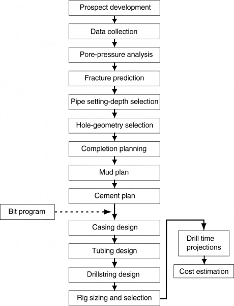
Well planning is an iterative engineering process rather than a straight checklist. A revised formation-pressure model can change the mud weight; that may change casing setting depths, which in turn can change hole sizes, equipment requirements, and the drilling schedule.
- Define success: reservoir target, allowable target window, expected fluids, logging and completion requirements, and lifetime operating conditions.
- Build the evidence base: select geologically comparable offsets and review drilling reports, mud and bit records, geophysical logs, seismic interpretation, survey data, kicks, losses, and stuck-pipe events.
- Construct the subsurface uncertainty model: forecast formation tops, pore pressure, fracture resistance, temperature, and instability or loss zones, with confidence ranges.
- Design location and trajectory: use a consistent survey datum and assess targets, anti-collision, dogleg severity, torque and drag, hole cleaning, and casing-running feasibility.
- Select casing seats and hole geometry: check the open-hole pressure window and possible need for another liner; then verify the completion’s minimum clearances.
- Integrate fluids, hydraulics, equipment, and barriers: evaluate circulating pressures, trip effects, well-control loads, cementing, BHA limits, rig capacity, and surface facilities.
- Issue executable deliverables: section-by-section program, design assumptions, operational limits, monitoring and response triggers, contingency equipment, time/depth plan, and AFE.
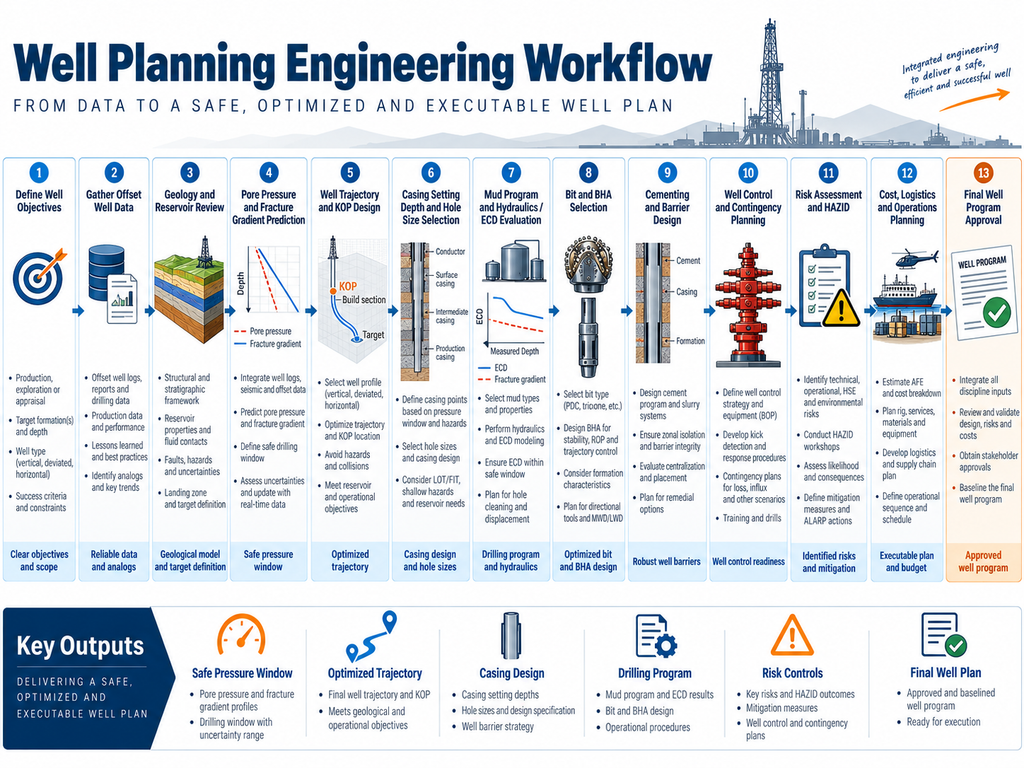
The drilling program is the operational product of this work. It should not conceal important assumptions inside separate spreadsheets that the rig team cannot readily review.
Well Plan vs. Drilling Program: What Is the Difference?
A well plan sets the design basis: targets, uncertainties, trajectory, hole and casing geometry, operating envelopes, hazards, cost assumptions, and contingency logic. A drilling program converts that approved basis into an executable sequence of hole sections, procedures, tests, equipment, operating limits and decision points for the rig team. A change to the subsurface model can therefore require revisions to both documents.
Use Offset-Well Planning Records as Evidence, Not as a Template
SPE Drilling Engineering, Chapter 11.2, identifies offset selection and data quality as early design requirements. The nearest well is not automatically the best reference: it may lie across a fault, penetrate a different pressure compartment, use a different mud system, or have a different trajectory.
| Evidence to review | What it helps establish | What must be questioned |
|---|---|---|
| Daily drilling and IADC reports | Depths of losses, influxes, stuck pipe, tight hole, NPT and casing decisions | Whether the event description and depth reference are reliable |
| Mud records and mud logs | Mud-weight history, gas indications, fluid properties and returns | Whether the reported density was static, circulating or measured after dilution |
| Bit and BHA records | Formation response, ROP, dull grade, vibration and bit-trip frequency | Whether bit type, WOB, RPM and hydraulics are comparable |
| Logs, surveys and seismic | Formation tops, faults, trajectory and pressure indicators | Depth conversions, seismic uncertainty and geological correlation |
| Casing, cement and shoe tests | Prior casing seats, isolation issues, formation-strength measurements | Whether test methods and acceptance criteria match the new design |
Practical planning improvement: create an offset-hazard register with the columns well / measured depth / TVD / event / evidence / confidence / effect on our plan. Record conflicting evidence instead of averaging it away. For example, a reported kick in one fault block should not silently be dismissed because several distant offsets drilled normally.
A good assumption register separates observed facts (such as a documented loss event) from interpretations (such as a predicted permeable or depleted zone) and design allowances chosen to manage uncertainty.
Surface Location, Reference Datum and Target Coordinates
Define the surface slot and subsurface targets in one coordinate reference system. Specify the horizontal datum, projection, grid-to-true-north conversion, rig/rotary-table elevation, and the vertical reference used for TVD. A location error can be created simply by mixing grid and true azimuths or depths referenced to different elevations.
Translate the geological target into a 3D window rather than a single point. Check surface access, rig footprint, nearby wells, faults, seabed or environmental restrictions, and the ability to reach the reservoir without unacceptable directional or completion loads. For directional design details, see well-trajectory calculations and profile planning.
Target Size: Cost Versus Accuracy
A smaller geological target window may require closer positional control, additional surveys, geosteering, or more expensive steering equipment. But targeting accuracy also depends on uncertainty in the formation model and survey measurements; a precise tool cannot correct an incorrectly positioned geological target.
Decision to document: target center and boundaries, allowable vertical and lateral miss, expected positional uncertainty, and the action to take if the reservoir interpretation changes while drilling. Have geology and reservoir engineering approve the acceptable landing window, not just the planned centreline.
Communication, Reviews and Design Ownership
The subsurface and drilling teams should jointly approve the target, pore-pressure model and casing-seat rationale. Completion engineering must confirm that the proposed hole and casing geometry can accept the production system. Drilling fluids, cementing, directional drilling, rig operations and HSE specialists then verify their respective operating envelopes.
Hold specific review gates for basis of design, casing/mud-pressure window, trajectory and collision risk, and pre-spud readiness. Assign each unresolved high-consequence assumption to an owner and an evidence-based closure action. A material change in the pore-pressure forecast, target or casing seat should trigger formal engineering review before the program is amended.
Wellbore Profile
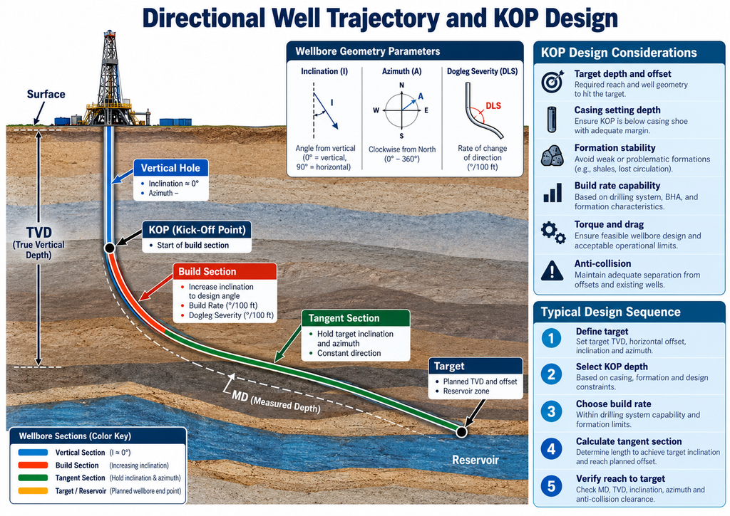
After fixing surface and target coordinates, compare vertical, build-and-hold (slant), build-and-drop (S-profile), and horizontal trajectories. The shortest measured depth is not necessarily the easiest or cheapest well to drill. Each candidate should be screened against geological targets, offset-well separation, torque and drag, hole cleaning, directional tool capability, casing runability and completion access.
The well path should be represented by planned survey stations containing measured depth (MD), inclination, azimuth, true vertical depth (TVD), northing/easting, and calculated dogleg severity (DLS). Use the directional well profiles guide for the main profile families.
Determining the Kick-Off Point
The kick-off point (KOP) must be chosen with both geometry and drillability in mind. Building angle through an unstable interval, hard stringer or restricted casing section may be impractical even if the calculated trajectory reaches the target.
- Confirm the formation is suitable for reliable directional control and survey quality.
- Ensure enough distance remains to meet the target with a realistic build/turn capability and steering uncertainty.
- Check that planned inclination and doglegs permit logging, casing, liner, completion and future intervention access.
- Review anti-collision separation throughout build and turn intervals, not only at the target.
Build and Drop Rate: A Mechanical Constraint
Build/drop rate and dogleg severity are often expressed in degrees per 100 ft (or degrees per 30 m). These are not interchangeable in a three-dimensional trajectory: DLS measures the combined change in inclination and azimuth between survey stations.
Geometry illustration: in a simple constant-azimuth build section, a planned 2°/100 ft build over 1,200 ft changes inclination by approximately 24°. That arithmetic says nothing about whether the section is mechanically acceptable. The BHA, tubular bending limits, torque and drag, casing forces, logging access and formation behaviour must all be checked.
Excessive curvature can raise contact loads, increase torque and drag, complicate casing running, and contribute to keyseating or fatigue. Use calculated profiles and dogleg-severity calculations, together with torque-and-drag modelling, rather than adopting a universal “acceptable” build rate.
The Pressure Window Determines What Can Be Drilled Open Hole
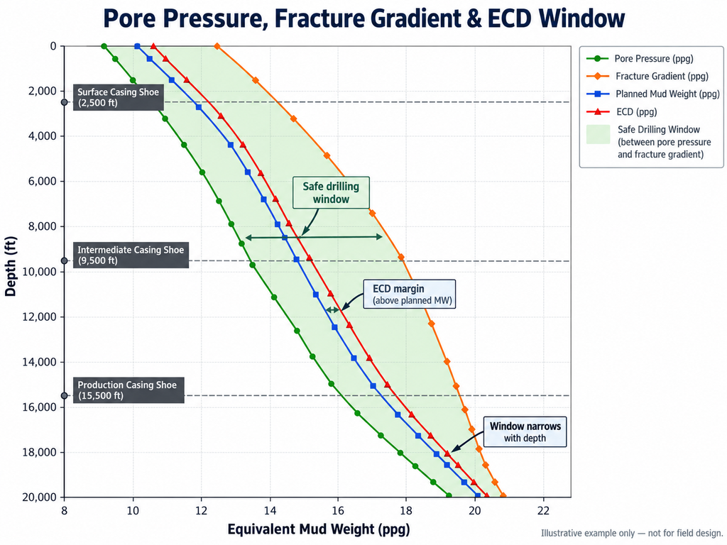
The pore-pressure/fracture-strength forecast is a design boundary, not merely a mud-weight chart. Mud pressure must control relevant formation influx and stability risks while circulating and tripping pressures remain compatible with the weakest exposed interval. The allowed window changes as formations are drilled and casing is set.
For each hole section, compare pore-pressure equivalent density (see pore-pressure prediction methods), wellbore-stability requirements, static mud density, expected equivalent circulating density (ECD), surge/swab scenarios, and estimated or tested formation strength. All of them must be compared at the correct depth and pressure reference.
| Condition | Engineering check | Design consequence |
|---|---|---|
| A higher-pressure zone is expected below a weak exposed formation | Can the required hydrostatic pressure and circulating pressures be sustained without breaking down the weak zone? | Change casing seat, mud/hydraulics design, or hole-section plan |
| A depleted or loss-prone zone will remain exposed | Will the fluid and transient pressure profiles cause losses or instability? | Reassess density, fluid properties, pressure-management method, or isolation |
| Uncertain pressure transition lies near section TD | Can credible high/low cases still be drilled and controlled? | Add uncertainty allowance, monitoring point and pre-approved contingency |
| Surface/intermediate casing shoe will see a kick load | Do formation integrity and well-control calculations support the planned open-hole interval? | Recalculate shoe depth, kick tolerance and equipment requirements |
SPE Drilling Engineering, Chapter 11.3, uses pressure and fracture-strength relationships to select casing seats; it also distinguishes deep-casing decisions from shallow casing designs that may be driven by kick-imposed loads. This is why an isolated mud-weight plot cannot replace a full casing-seat and well-control assessment.
Worked Example: Why ECD Can Change a Casing Decision
Illustrative numbers only — not field operating limits. At a selected evaluation depth of 10,000 ft TVD, assume the highest credible pore-pressure equivalent is 12.8 ppg and the lowest credible pressure equivalent associated with loss/fracture onset is 13.6 ppg. The proposed static mud weight is 13.0 ppg. If the relevant annular friction contribution at that same depth is 250 psi, the calculated ECD is:
ECD (ppg) = mud weight (ppg) + annular friction pressure (psi) / [0.052 × TVD (ft)]. This is the standard form for the specified evaluation depth; see the SLB Energy Glossary definition of ECD for the underlying pressure-loss terminology.
ECD = 13.0 + 250 / (0.052 × 10,000) ≈ 13.48 ppg.
The apparent circulating margin below the illustrative 13.6-ppg limit is only 0.12 ppg. Separately, the static 13.0-ppg mud is just 0.2 ppg above the stated maximum pore-pressure equivalent, before considering uncertainty, swab effects or required safety margins.
Engineering interpretation: this example does not justify the program. It highlights a narrow, uncertainty-sensitive window. A planner should verify the pressure/fracture model, hydraulic losses and transients; review operational margins; and assess whether a different casing seat or drilling method is warranted. Values for a casing shoe, bottomhole and other weak zones cannot be assumed interchangeable.
Select Casing Seats and Hole Sizes Together
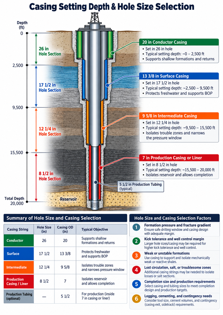
The casing program serves two separate but connected purposes: isolate formations and pressure regimes, and leave a practical internal diameter for subsequent drilling and completion. Plan from the final completion dimensions upward, while checking casing setting depths against the predicted pressure window from each drilling section downward.
- Confirm the minimum tubing, packer, artificial-lift, logging or intervention clearance required at the reservoir.
- Choose a feasible production casing or liner and bit-size sequence, checking actual drift and connection clearances.
- Place intermediate casing or liners where they are needed to isolate incompatible pressure regimes or persistent instability/loss zones.
- Test proposed shoe depths against expected open-hole mud/ECD, swab/surge, shoe integrity and kick tolerance.
- Leave a defensible contingency if another string or liner must be run; verify whether the smaller resulting diameter would still permit completion.
A well can appear economical in the base case but become uncompletable after an unplanned contingency string. Test that outcome on paper before approving the geometry. See casing design calculations for the separate detailed load checks covering burst, collapse, tension and combined loading.
Drilling Fluids, Hydraulics and Hole Cleaning Are Linked to the Casing Plan
After establishing a provisional pore-pressure and fracture-strength window, develop the fluid-density plan, rheology, filtration control, inhibition needs, solids-management targets, and the circulating hydraulics. Mud design and casing-seat selection must be iterated: a fluid required for pressure control may produce unacceptable ECD or losses unless the casing program or circulation design changes. See drilling-fluid engineering calculations for the quantitative inputs that support this review.
In inclined or horizontal sections, the cleaning system must be checked against the anticipated cuttings load, wellbore inclination, annular velocity and rheology; a high nominal pump rate alone does not demonstrate adequate hole cleaning. The chosen bit, BHA, motor or rotary-steerable tools, and pump capabilities must also fit the available hydraulic envelope.
A Useful Well Planning Risk Register
Rather than writing generic “monitor well conditions” instructions, define observable warnings, decision authority and planned engineering response. The entries below are examples of how to structure the plan; actual thresholds must be established for each well.
| Potential deviation | Evidence or trigger to define | Planned decision |
|---|---|---|
| Pore pressure higher than forecast | Change in interpreted formation indicators, calibrated pressure data or documented influx | Update the pressure model and confirm barriers and mud/casing envelope |
| Formation weaker than predicted | FIT/LOT result or recurring losses inconsistent with design | Reassess shoe integrity, ECD, fluid and next section depth |
| Directional response differs from plan | Survey deviation, build rate or tool response outside approved tolerance | Recalculate target reach, anti-collision and casing-running risks |
| Increasing mechanical restriction | Abnormal torque/drag, persistent tight spots or poor returns | Review hole cleaning, stability, sticking mechanisms and contingency |
| Critical equipment or materials unavailable | Failure to meet the pre-spud assurance schedule | Close the readiness gap or formally revise the execution plan |
A practical risk register should record the hazard, its consequence, current evidence, owner, surveillance method, decision point and contingency. It is useful both during planning and during daily drilling reviews.
Time, Cost and the AFE: Compare Scenarios, Not Just a Single Budget
The Authority for Expenditure (AFE) should be built from the technical well design and a depth-versus-days forecast. SPE Drilling Engineering, Chapter 11.5, connects the time estimate to rig, drilling fluids, rental equipment, cementing, logistics, tubulars and completion costs.
Separate the base case from credible delay or contingency scenarios. For example, if a section is forecast to require four additional rig days, the direct rig-day effect alone is 4 × the applicable daily rig cost; services, tools, rentals and other time-dependent charges may add to it. This reveals the economic value of an alternative design without pretending it removes uncertainty.
A well with fewer planned casing strings may have a lower base-case AFE yet a larger exposure to lost circulation, pressure escalation or an unplanned liner. Compare both expected cost and the consequences of credible failure modes; do not select solely by the lowest initial estimate.
Pre-Spud Readiness: What the Rig Team Should Receive
- Approved well objectives: target coordinates, accepted window, formation-top prognosis, final hole/completion requirements and survey references.
- Section-by-section schematic: hole and casing sizes, planned seats, cement isolation intent, BOP/pressure-control configuration, and relevant shoe-test requirements.
- Pressure design pack: pore/fracture uncertainty envelope, fluid weights, ECD forecasts, well-control and kick-tolerance calculations, and the associated assumptions; include a specific H2S well-planning review where sour formations are credible.
- Trajectory execution pack: survey program, KOP, steering limits, anti-collision controls, DLS and torque/drag predictions.
- Operating envelopes: tubing/rig capacities, pump and hydraulic limits, BHA/bit requirements, casing-running restrictions and contingency materials.
- Surveillance and decision plan: risk register, specific review triggers, change-control authority, emergency response and end-of-well learning capture.
The planning team should be able to answer a simple question for every critical limit: what observation would make us stop relying on this assumption, and who is authorized to change the program? This is more valuable than a generic safety statement.
Technical Sources and Scope
Primary technical reference: Robert F. Mitchell (ed.), Petroleum Engineering Handbook, Volume II: Drilling Engineering, Society of Petroleum Engineers, 2006; especially Neal Adams, Chapter 11, “Introduction to Well Planning,” Sections 11.1–11.5, and Chapter 7, “Casing Design.” The planning workflow, offset-record review, casing-seat logic, hole-geometry relationship, and AFE considerations are independently explained here rather than reproduced from the handbook.
Additional uploaded references: Well Planning training notes (well types, data collection, planning deliverables) and the historical ADCO Drilling Manual (2005) for examples of risk-based planning, zonal isolation and design-review controls. The historical company manual illustrates engineering governance, not current regulatory requirements.
Engineering note: All worked numbers and risk-register entries above are educational examples. Final well design must use validated field data, current applicable requirements, certified equipment limitations and formal multidisciplinary approval.