Dogleg severity is a measure of the amount of change in the inclination, and/or azimuth of a borehole usually expressed in degrees per 100 feet of course length. In the metric system, it is usually expressed in degrees per 30 meters or degrees per 10 meters of course length. All directional drilling wells have changes in the wellbore course and, therefore, have some dogleg severity. If not, it would not be a directional well. The dogleg severity is low if the changes in inclination and/or azimuth are small or occur over a long interval of course length. The dogleg severity is high when the inclination and/or azimuth changes quickly or occur over a short interval of course length. In this article, we will discuss the formulas & charts that used in dogleg severity DLS calculations in oil and gas wells and we will provide examples for that.
In general, you can calculate dogleg severity by dividing the difference in the inclination angles for 2 certain points on the distance between these 2 points. This equation can be used only if there were only changes in the inclination on the wellbore which is impossible to occur. The other main formula for dogleg severity is more accurate as it takes into account both inclinations and azimuth.
Dogleg Severity Problem In Drilling
Doglegs are not necessarily a problem in directional wells. When a dogleg becomes a problem, then it is considered severe.
Torque & Drag
One of the immediate problems associated with doglegs is torque and drag. More severe doglegs will cause higher torque and drag. The drill string will experience less torque from a dogleg while drilling because the Drill collars are in compression except in the case of a horizontal well or high inclination well. However, while tripping or reaming in drilling, the torque will be greater because the collars are in tension and increase the overall tension in the drill string. In a horizontal or high inclination well, the torque may be lower while rotating off the bottom. Care should be taken when tripping after a significant change in hole inclination and/or direction. The bottom hole assembly may go to the bottom, but it might not come back up through the dogleg. An assembly should never be forced to the bottom; it should be reamed to the bottom.
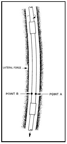
Torque and drag are caused by the friction between the drill string (check drill string components) and the borehole wall. When the drill string is in tension, it tries to straighten while going around a dogleg. The drill string exerts a force on the formation as shown in Figure 1. As tension on the drill string increases (depth below dogleg increases) the lateral force increases; therefore, the torque and drag increase.
The torque and drag can be reduced by several different means. One method is to keep the dogleg severity low. Once a severe dogleg exists in the wellbore, its effect can be decreased somewhat by reaming but only by a small amount. Torque and drag can be reduced using lubricants in the mud system. Oil and other commercially available lubricants reduce the coefficient of friction between the drill string and borehole wall; thereby, reducing the torque and drag. Another method is to reduce the tension in the drill string. This can be accomplished by removing excess collars or replacing the collar with a heavy weight drill pipe. The heavy-weight drill pipe is more flexible and reduces the overall string weight while maintaining the same available bit weight.
Keyseats
As drilling continues, the drill string tension in the dogleg increases which increases the lateral force. The lateral force causes the drill string to cut into the wellbore wall at the dogleg. A keyseat is formed if the lateral force is large enough to cut into the wall. Soft formations require a lower force than hard formations to form a keyseat.
String Wearing
Other problems associated with severe doglegs are wearing of tool joints and worn spots in the casing which can lead to collapse or a hole in the casing. Logging tools and drill collars can become stuck ( check also free point calculation for stuck pipe) in a keyseat drilling that is considered one of the Mechanical Sticking problems.
Drill Pipe Fatigue
Drill pipe fatigue is also associated with doglegs. Most failures in drill pipes are fatigue failures resulting from gradual progressive growth of minor irregularities into major cracks even when the stresses are less than the yield strength of the metal. Figure 1 illustrates how a severe dogleg can cause fatigue failures. Point “A” on the drill pipe is in maximum tension while point “B” is in minimum tension due to bending. (If there is no weight hanging below the joint of drill pipe, point “A” would be in tension, and point “B” would be in compression.) As the pipe is rotated, the reference points go through cyclic stress reversals. Point “A” goes from maximum tension to minimum tension and back to maximum tension on each cycle. These cyclic stress reversals will cause fatigue failures. The failures usually occur within 2 feet of a tool joint because this is the point of the internal upset. They also occur in the slip area.
The cycles to failure are a function of the degree of bending, yield strength of the pipe, wall thickness, corrosive environment, and the tensile load on the pipe. The degree of bending is calculated by the dogleg severity and the diameter of the pipe. It should be remembered that the dogleg severity is a measure of the curvature between survey points. This may not be a true indication of the actual dogleg severity. As an example, assume a drilling whipstock was used to change the inclination of a well. Calculations from a 100 foot survey interval indicated a dogleg severity of 3°/100 feet. The fact is that most of the inclination change occurred while drilling off the whipstock which is approximately 10 feet long. The remainder of the survey interval has only a small amount of curvature. A survey taken above and below the whipstock indicates a 3° change in 10 feet. The degree of bending is determined by the actual dogleg severity.
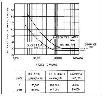
The yield strength of metal has less effect on fatigue failure than one might think. Even though the yield strength of the S-135 drill pipe is 1.8 times greater than the Grade “E” drill pipe, the endurance limit is only 1.12 times greater. The endurance limit is the maximum alternating stress a material can take without causing fatigue. Figure 2 is a plot of the alternating stress versus the cycles to failure for grade D and E pipe and S-135 pipe. The endurance limit for Grade E and S-135 pipe is 26,000 psi and 29,000 psi, respectively. However, these values are with no tension in the pipe and no corrosion. As tension and corrosion rates increase, the maximum bending stress (dogleg severity) without causing fatigue will decrease.
Wall thickness does have an effect on the cycles necessary to produce failure in a dogleg. Pipe with a greater cross-sectional area will endure more cycling because the total stress per unit area is lower with the same amount of tension.
Corrosive environments such as saltwater reduce the cycles to failure for drill pipes. As corrosion rates increase, the endurance limit decreases. Drill pipes will have more fatigue failures while drilling wells in corrosive environments. Corrosion pitting will also decrease the service life of the drill pipes. Pitting reduces the cross-sectional area of the drill pipe which increases the alternating stress per unit area. Also, scars inside or outside the pipe reduce the cycles to failure for drill pipe.
Tensile loading has a significant effect on the cycle to failure. Increases in tensile loads increase the total stress on the pipe. Since the stress per unit is greater, the failure will occur at fewer cycles. Therefore, if a dogleg is high in the hole with high tension in the pipe, only a small dogleg severity can be tolerated. If a dogleg is close to the bottom of the hole with low tension on the pipe, larger dogleg severities can be tolerated.
Fatigue damage in the drill pipe is cumulative. If a joint of drill pipe rotates in a severe dogleg while drilling, some portion of its life is used. Even though the joint did not fail when drilling the hole with the severe dogleg, a failure can occur in the next hole where the dogleg severity is much less. Conventional inspection techniques cannot measure the amount of fatigue damage that has already accumulated unless a crack is present.
The Simple Formula For Dogleg Severity Calculations
As we mentioned above this formula is used if we neglected the azimuth change.
DLS = Δ I / ΔMD
I: represent the inclination
MD: represent the measured depth
To show how a change in inclination can affect dogleg severity calculation, consider the following example:
Example # 1
Given:
- MD1 = 1000 ft
- MD2 = 1100 ft
- I1 = 4°
- I2 = 6°
Requirement:
Perform dogleg severity calculation.
Solution:
The change in inclination is:
ΔI= I2 − I1
ΔI= 6 – 4 = 2°
The course length over which the change in inclination occurred is:
Δ MD = MD2 – MD1
ΔMD =1100.00 − 1000.00 = 100.00 ft
Calculation of dogleg severity:
DLS = Δ I / ΔMD
DLS = 2 / 100
Therefore, the dogleg severity is 2°/100 feet.
Suppose I2 is equal to 8°, then
ΔI = I2 – I1
Δ I = 8 − 4 = 4°
ΔMD = MD2 − MD1
Δ MD = 1100.00 − 1000.00 = 100.00 ft
DLS = ΔI / ΔMD
DLS = 4° / 100
The dogleg severity is 4°/100 feet. A greater change in inclination yields a larger dogleg severity.
Example # 2: Dogleg Severity & Change In Course Length
To show how the change in course length can affect dogleg severity, consider the following example:
Given:
- MD1 = 1,000 feet
- MD2 = 1,050 feet
- I1 = 4°
- I2 = 6°
Requirement:
Calculate The dogleg severity.
Solution:
ΔI = I2 − I1
Δ I = 6 − 4 = 2°
Δ MD = MD2 − MD1
Δ MD = 1050.00 − 1000.00 = 50.00 ft
DLS = 2° /50
DLS = 4° / 100 ‘
The dogleg severity is 4°/100 feet. Example 1 and Example 2 show that for the same change in inclination, a shorter course length will result in a greater dogleg severity.
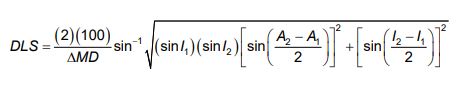
The Accurate Formula For Dogleg Severity Calculations
The previous examples were simplified cases in which only the inclination was changed and the azimuth remained constant. A change in azimuth also affects dogleg severity. Unfortunately, the effect on dogleg severity due to a change in azimuth is not as easy to understand or calculate. A 2° change in azimuth in a 100-foot course length will not yield a dogleg severity of 2°/100 feet unless the inclination is 90°. At low inclinations, a change in azimuth will have a small dogleg severity. As the inclination increases, the dogleg severity will also increase for the same change in azimuth. Three formulas for calculating dogleg severity using both inclination and azimuth are shown below.
Formula 1 :
DLS = (100 / ΔMD) cos−1 { (sin I1 × sin I2 ) [(sin A1 × sin A2 ) + (cos A1 × cos A2 )] + (cos I1 × cos I2 ) }
The first two equations are very long and it is easy to make a mistake in the calculations. Equation 3 is more simple but not very accurate below an inclination of 5°. The nomenclature is the same as for the survey calculations.
In formulas 1 through 3, the “100” changes the dogleg severity to “per 100 feet”. In the metric system, the “100” should be changed to “30” for dogleg severity in degrees per 30 meters or “10” for dogleg severity calculations in degrees per 10 meters.
To illustrate the effect azimuth has on dogleg severity, consider the following problem.
Example 3: Considering The Azimuth Changes
Given:
A 10° azimuth change at inclinations of 1°, 10°, 20°, 30°, 40°, 50°, 60°, 70°, 80°, and 90°.
Requirement:
Determine The dogleg severity at each inclination.
Solution:
To make the problem easier to understand, a table can be set up with the necessary information (see Table 1).
| I2 | A2 | I1 | A1 | ΔMD |
| 1 | 20 | 1 | 10 | 100 |
| 10 | 60 | 10 | 70 | 100 |
| 20 | 100 | 20 | 90 | 100 |
| 30 | 140 | 30 | 150 | 100 |
| 40 | 180 | 40 | 170 | 100 |
| 50 | 210 | 50 | 220 | 100 |
| 60 | 230 | 60 | 220 | 100 |
| 70 | 270 | 70 | 280 | 100 |
| 80 | 300 | 80 | 310 | 100 |
| 90 | 360 | 90 | 350 | 100 |
Calculate the dogleg severity at 1° using Formula 1. In this example, the inclination remains constant at 1°. The azimuth will change from 10° to 20° over a course length of 100 feet.
DLS = (1) cos−1 {(0.0175 × 0.0175)[(0.1736 × 0.3420) + (0.9848 × 0.9397)] + (0.9998 × 0.9998)}
DLS = (1) cos−1 (0.9999) = (1)(0.1743 )
DLS = 0.17° / 100 ‘
Calculate the dogleg severity at a constant inclination of 10° using Formula 1.
DLS = (100 / ΔMD) cos−1 { (sin I1 × sin I2 ) [(sin A1 × sin A2 ) + (cos A1 × cos A2 )] + (cos I1 × cos I2 ) }
DLS = 100 / 100 x cos−1 { (sin10 × sin10) [(sin 70 × sin 60) + (cos 70 × cos 60)] + (cos10 × cos10) }
DLS = (1) cos−1 { (0.0301) (0.9848) + (0.9698) }
DLS = (1) cos−1 (0.9995)
DLS = (1)(1.73)
DLS = 1.73° / 100 ‘
Calculate the dogleg severity at a constant inclination of 20º using Formula 1.
DLS = 100 / 100 x cos−1 { (sin 20 × sin 20) (sin 90 × sin100) + (cos 90 × cos100) + (cos 20 × cos 20) }
DLS = (1) cos−1 { (0.1170) (0.9848 + 0.0000) + (0.8830) }
DLS = (1) cos−1 (0.9982)
DLS = 3.42° / 100 ‘
The dogleg severity for the remaining constant inclinations was calculated and is shown in Table 2.
At an inclination of 1°, the dogleg severity is 0.17°/100 feet for a 10° change in azimuth. At an inclination of 50°, the dogleg severity is 7.66°/100 feet for the same change in azimuth. The results in Table 2 show that the dogleg severity increases as the inclination increases for the same change in azimuth. The equation used to calculate the dogleg severities in Table 2 can also be used to calculate the dogleg severity in Example 2.
| I1 & I2 | DLS |
| 1° | 0.17°/100’ |
| 10° | 1.73°/100’ |
| 20° | 3.42°/100’ |
| 30° | 5.00°/100’ |
| 40° | 6.42°/100’ |
| 50° | 7.66°/100’ |
| 60° | 8.66°/100’ |
| 70° | 9.40°/100’ |
| 80° | 9.85°/100’ |
| 90° | 10.00°/100’ |
Example 4
Given:
The data in Example 2 plus A1=42º and A2=42º.
Requirement:
Determine The dogleg severity using Equation 1
Solution:
DLS = 100 / 50 cos−1 {(sin 4 × sin 6) (sin 42 × sin 42) + (cos 42 × cos 42)+ (cos 4 × cos 6 )}
DLS = (2) cos−1 {(0.0073) (0.4477 + 0.5523) + (0.9921)}
DLS = (2) cos−1 (0.9994)
DLS = 4° / 100 ‘
The dogleg severity is the same as calculated previously. The formula can be used to calculate dogleg severity for any combination of changes in azimuth, inclination, and measured depth.
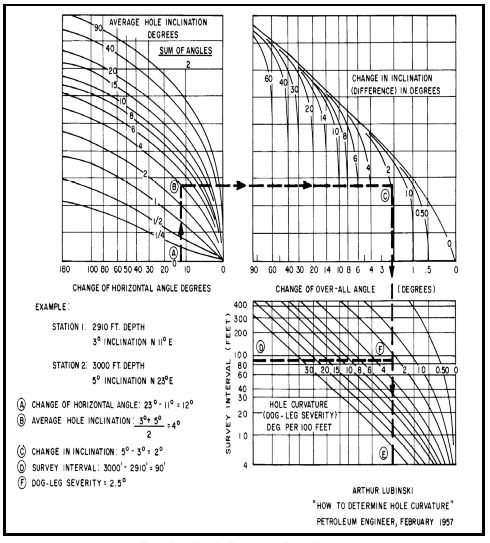
Dogleg Severity Graphs
Instead of these Formulas, Figure 3 can also be used to determine dogleg severity. The graph is relatively easy to use, and the likelihood of making a mistake is smaller. An example of how to use the charts is included on the chart.
Dogleg Severity Limit Calculations Formula
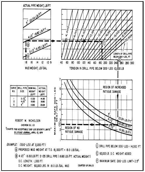
Figure 4 and Figure 5 can be used to calculate the maximum dogleg severity that can be tolerated in a well based upon tension. Examples for determining the maximum dogleg severity are shown in each figure. Usually, if the directional program is designed to prevent drill pipe fatigue, the hole will be acceptable for conventional designs of the casing, tubing, and sucker rods. However, rod and tubing wear will occur in directional wells.
As the corrosion rates increase, the maximum safe dogleg severity limit will decrease. In Figure 3, the endurance limit for grade E drill pipe is 26,000 psi, but that is for a corrosion-free environment. Lubinski indicated that the endurance limit for a normal drilling mud would be around 18,000 psi for grade E drill pipe. A simple equation for calculating the bending stress in pipe is Equation 4 and can be used when there is no tension. Lubinski’s equations should be used when there is significant tension in the drill pipe.
σb = ±(218)(Dp )(DLS )
Example 5 To Calculate The Dogleg Severity Limit
Example 5 shows how the maximum dogleg severity limit can be calculated for no tension load if the endurance limit is known.
Example 5
Given:
The endurance limit for grade E drill pipe is assumed to be 18,000 psi.
Determine:
The maximum permissible dogleg severity with no tensile stress for 4 1/2” drill pipe
Solution:
Rearranging Equation 4 to solve for dogleg severity
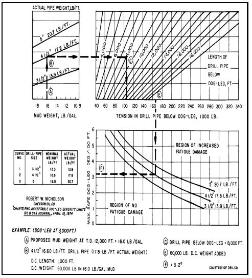
σb = ±(218)(Dp )(DLS )
DLS = σb / ( ± 218 x Dp ) = 18000 / (218) (4.5) = 18.3o / 100 ft
Higher dogleg severities can be tolerated if the tension in the drill pipe is very low. Medium radius horizontal wells can be drilled without causing significant fatigue damage to the drill pipe because the tension in the dogleg is very low. The dogleg severity in a normal directional well has to be lower at the kickoff point because the tension will be a maximum at that point. The deeper the dogleg, the greater the dogleg severity that can be tolerated without causing fatigue.
Ref:
Lubinski, A.; “Maximum Permissible Dog-Legs in Rotary Boreholes,” Journal of Petroleum Technology, February, 1961
Many Thanks!