The common drill pipe length is basically from 27-30 feet, which is classified as range-2 R2. This article will discuss their range and how to perform their design.
What is The Common Drill Pipe Length Ranges
The Drill String is made up of several sections of Drill Pipes. The term “stand” consists mainly of two or three drill pipe joints, which are 60 to 90 feet long. Every joint of pipe is referred to as a “single.”
According to API, there are three ranges of drill pipe length: R1, R2, and R3.
- Range 1 (R1) is the shortest length, more common for sizing production tubing or Casing, and ranges from 18 to 22 ft.
- Range 2 (R2) is considered the standard length for the Pipe, ranging from 27 to 31 ft.
- Range 3 (R3) is common in Casing and also deployed in deepwater drilling applications.
The increased length decreases the number of tool joints in each stand of drill pipe. The fallback is that the load exerted on each tool joint is greater, increasing wear and reducing the expected life of the drill pipe. R3 ranges from 38 to 45 ft.
How To Perform Drill Pipe Design
The Drill String is designed so that the uppermost joint of each section of the Drill Pipe is loaded to no more than 80% of the minimum tensile yield strength of that particular weight and grade pipe for a single size and grade drill pipe.
The total load exerted on the drill pipe’s top joint consists of the drill pipe’s buoyed weight plus the bottom hole assembly (heavy-weight drill pipe plus drill collars) and the margin of overpull (MOP). The MOP is the desired amount of load over the buoyed weight of the drill string to account for hole drag and provide excess pull capacity if the drill string becomes stuck in the hole. The amount of overpull ranges from 50,000 to 100,000 lb.
The design criterion can be expressed as,
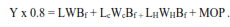
Where,
- L: length of drill pipe, ft.
- W: Actual weight of drill pipe, lb/ft.
- Lc: length of drill collars, ft.
- Wc: weight of collars, lb/ft.
- LH: length of Heavy Weight, ft.
- WH: weight of heavy-weight drill pipe, lb/ft.
- MOP: Margin of overpull, lb.
- Bf: buoyancy factor.
- Y: minimum yield strength, lb.
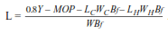
Solving above Eq for the maximum length of pipe that can be used,
If the Drill String Design includes two sections of drill pipe of different grades and weights (Api drill pipe Specs), then the maximum length of the second section (top section) is,
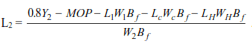
Where,
- L1: length of the first section of pipe (lower section), ft.
- W1: the actual weight of the first section of drill pipe, lb/ft.
- L2: Pipe length of the second section, ft.
- W2: the actual weight of the second section of drill pipe, lb/ft.
- Y2: minimum tensile strength of the second section of drill pipe (top section), lb.
In drill string design, the pipe of the lowest grade (weakest) is placed on the bottom.
Each section of the Drill Pipe is designed starting with the Bottom Hole Assembly BHA and working upwards. This design is checked at various depths, for the most critical section of the hole is often not at TD but further up the hole due to mud weight changes.
Design Of 3 Different Sections Of Drill Pipes
The First Section
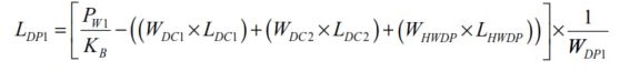
- LDP1= Maximum Length of Pipe in Section 1 (ft).
- PW1= Working Load of Drill Pipe in Section 1 (lbf).
- KB= Buoyancy Factor.
- WDC1= Air weight of Drill Collars in 1st Section, per unit length (lb/ft).
- LDC1= Length of Drill Collars in 1st Section (ft).
- LDC2= Air weight of Drill Collars in 2nd Section, per unit length (lb/ft).
- WDC2= Length of 2nd Section of Drill Collars (ft).
- WHWDP= Air weight of HWDP, per unit length (lb/ft).
- LHWDP= Length of HWDP (ft).
- WDP1= Air Weight of Pipe in Section 1,per unit length (lb/ft).
The Second Section
The maximum length of the second section above the BHA is:
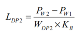
- LDP2= Maximum Length in Section 2 (ft).
- PW2= Working Load of Drill Pipe in Section 2 (lbf).
- PW1= Working Load of Drill Pipe in Section 1 (lbf).
- WDP2= Air weight of Drill Pipe in Section 2, per unit length (lb/ft).
- KB= Buoyancy Factor.
The Third Section
The maximum length of the third Pipe section above the BHA is:
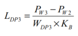
- LDP3= Maximum Length of Section 3 (ft).
- PW3= Working Load of Drill Pipe in Section 3 (lbf).
- PW2= Working Load of Drill Pipe in Section 2 (lbf).
- WDP3= Air weight of Drill Pipe in Section 3, per unit length (lb/ft).
- KB= Buoyancy Factor.