This article discusses gyro wellbore survey tool services available today in the oil and gas industry, beginning with basic gyroscopic theory and leading up to Rate Gyro technology. There is no attempt to compare systems or provide an expert technical description of any company’s technology. The intent is instead to provide a basic understanding of gyro technology, its background, goals, and place, among other surveying methods.
Application Of Gyro Tool In Directional Drilling Surveying
Compass readings are typically used to determine the well’s direction when conducting magnetic surveys. However, these readings can be unreliable in cased or open holes near cased wells. In such situations, an alternative method is necessary to assess the well’s direction accurately. A gyroscopic compass can be used to evaluate the well’s inclination similarly to magnetic tools, but it eliminates the magnetic effects that can interfere with accuracy.
Mechanism Of Gyro Tool
A Gyroscope is a wheel that spins around one axis but can rotate about one or both of the other axes since it is mounted on gimbals. The inertia of the spinning wheel tends to keep its axis pointing in one direction. Therefore, gyroscopic instruments use this spinning gyro to determine the direction of the well. There are four kinds of gyroscopic tools: conventional gyro, rate or north-seeking, ring laser, and inertial grade. In situations where magnetic survey instruments are unsuitable, such as in cased holes, the gyro can be an alternative tool.
The survey tool used in the oil and gas industry rotates a gyroscope with an electric motor at around 40,000 rpm. The tool aligns with True North on the surface and ensures that the gyroscope remains pointing in that direction as it runs into the hole, regardless of any forces that may attempt to deflect it.
A compass card is attached to and aligned with the gyroscope’s axis; this acts as the reference direction for all directional surveys. Once the tool has landed in the required position in the drill collars, the procedure is very similar to that for the magnetic single shot. Since the compass card is linked to the gyroscope’s axis, it records a True North bearing, which does not require correction for magnetic declination.
Film-Based Conventional Gyro
As mentioned, a film-based conventional gyro is available as a single-shot instrument. In areas where magnetic interference is present, like in cased holes or near other wellbores, film-based gyros are no longer commonly used for surveying and positioning deflection tools in oil and gas. Nowadays, gyros are typically run as multi-shots on an electric wireline. In addition, a computer is handling the information processing at the surface. Deflection tools can also be oriented by wireline gyros. Gyros are also available in measurement while drilling tools.
Gyro Tool Operating Forces
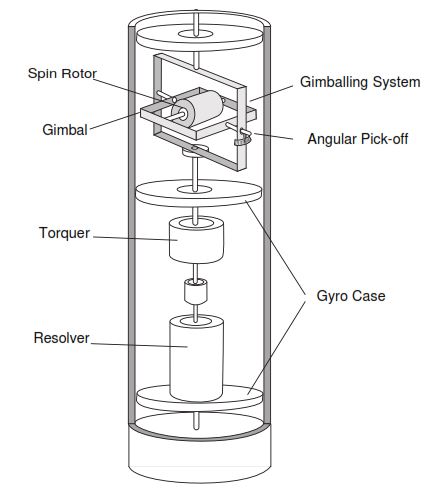
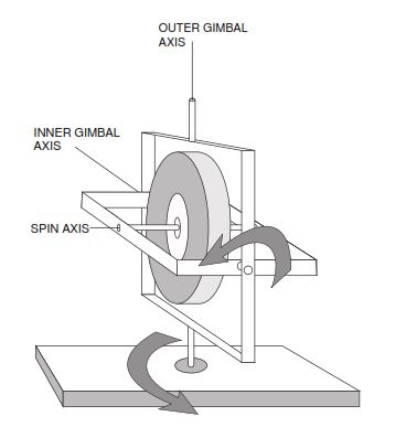
To understand the forces operating on gyroscopes, let’s begin by analyzing simplified gyroscopes. Simplified gyroscopes have frames called gimbals that support the gyroscope and enable freedom of rotation. Figure 1 shows a streamlined gyroscope within its housing in a typical well-surveying configuration.
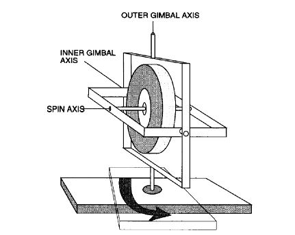
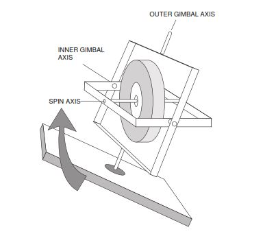
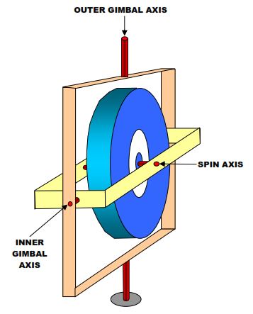
The gimbals isolate the gyro from the base so, as shown in Figure 2, the spinning mass can attempt to maintain its original orientation no matter how the base moves. The gyroscopes shown in Figure 4 are two-degree-of-freedom gyros.
As the probe moves downhole through different directions and inclinations, the gimballing allows the gyro to attempt to maintain a horizontal orientation in space.
In performing a wellbore survey, the gyro is pointed in a known direction before running in the well, so throughout the survey, the spin axis attempts to hold its surface orientation. Note that a compass card is aligned with the horizontal spin axis of the gyro. Survey data is collected downhole by affixing a plumb-bob assembly over the compass.
At each survey station, a picture of the plumb-bob direction concerning the compass card is taken, resulting in wellbore azimuth and inclination readings. The plumb-bob always points down toward the Earth’s center as a pendulum. When the tool is inclined vertically, it points out the inclination of the well on the concentric rings and the azimuth by correlation with the known direction of the gyro spin axis established at the surface. (Note: Electronic, surface read-out free-gyro systems also eliminate the plumb-bob.)

The Main Components Of the Oil & Gas Gyro Survey Tool
A gyroscope is a spinning wheel whose spin axis can move relative to some reference mount. For the sake of simplicity, the significant components of the gyro are comprised of:
- The Spin Motor, the main characteristic of which is “angular momentum.”
- The Gyro Case is the outer enclosure.
- The Gimballing System is the structure carrying the spin motor. The gimballing system isolates the spinning rotor from the gyro-case If the gyro-case turns around the outer gimbal axis (Figure 4-19).
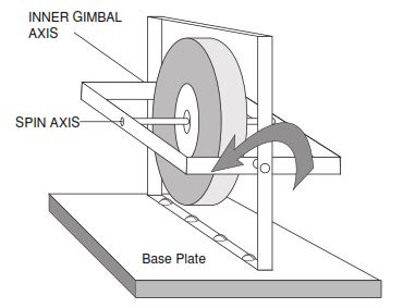
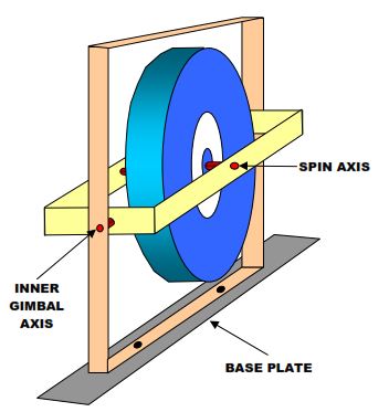
- If the gyro-case turns around the inner gimbal axis (Figure 4-20).
- The Gimbal suspension, which includes The ball bearings (or gimbal bearings) between the gyro-case and the outer gimbal and between the outer gimbal and the inner gimbal;
- The rotor bearings hold the spinning rotor in the inner gimbal.
- An Angular Pick-off which senses relative angular displacements between the gyro gimbal and the case.
- a Torquer, which enables compensation for certain types of errors and processing of the gyro at desired rates.
Gyroscopes are usually classified according to various characteristics, namely:
Use
- Instrument gyros such as artificial horizons and gyrocompass are used for measuring and indicating purposes.
- Control gyros are used to generate signals.
- Stabilizing gyros are used to generate torques for stabilizing purposes.
Construction and Function.
Two major types:
- A single degree of freedom gyro requires only one coordinate axis to locate the SPIN axis concerning the instrument mount (Figure 5). In a single-degree-of-freedom gyro, the spin axis is stabilized against rotation around the gimbal axis but is disturbed by rotations about the quadrature axis.
- Two degrees of freedom gyro in which the rotor spin axis can move concerning the case around two axes in an uncontrolled manner (Figure 6).
Restraints On The Movement Of The Spin Axis
- In a Single degree of freedom gyro, the spin axis may have An elastic restraint (rate gyro or gyrometer which measures the input angular velocity).
- A viscous restraint (rate integrating gyro, which measures the input angular displacement).
- No restraint (integrating gyro).
- In a Two-degree freedom gyro, the spin axis may be Completely free, except for unavoidable frictional restraints.
- Supplied with torques for correction or measurement purposes.
Gyro Survey Tool Types In Oil & Gas Wells
Conventional Gyro
The conventional gyro or free gyro has been around since the 1930s. It obtains the azimuth of the wellbore from a spinning gyro. It only determines the direction of the wellbore and does not determine the inclination. The inclination angle is usually obtained with accelerometers. The film-based, single-shot gyro uses a pendulum suspended above a compass card (attached to the outer gimbal axis) to get the inclination. A conventional gyro has a spinning mass usually turns at 20,000 to 40,000 rpm (some turn even faster). The gyro will stay fixed if no external forces act on it and the mass is supported at its exact center of gravity. Unfortunately, it is not possible to keep the mass at its precise center of gravity, and external forces do act on the gyro. Therefore, the gyro will drift with time. Figure 7 is a very simplified example of a conventional gyro.
Theoretically, if a gyro starts spinning and is pointed in a specific direction, it should not substantially change direction over time. Therefore, it is run in the hole, and even though the case turns around, the gyro is free to move, and it stays pointing in the same direction. Since the direction in which the gyro is pointing is known, the direction of the wellbore can be determined by the difference between the orientation of the gyro and the orientation of the case containing the gyro. The orientation of the spin axis must be known before the gyro is run in the hole. This is called referencing the gyro. If the gyro is not referenced correctly, the entire survey is off, so the tool must be appropriately referenced before it is run in the hole for oil and gas wells.
Disadvantages
Another disadvantage of a conventional gyro is that it will drift with time, causing errors in the measured azimuth. The gyro will drift due to system shocks, bearing wear, and the Earth’s rotation. The gyro can also drift due to imperfections in the gyro. The defects can develop during the manufacturing or machining of the gyro, as the exact center of the mass is not in the center of the spin axis. The drift is less at the Earth’s equator and higher at higher latitudes near the poles. Generally, conventional gyros are not used at latitudes or inclinations above 70°. A typical drift rate for a traditional gyro is 0.5° per minute. The apparent drift caused by the Earth’s rotation is corrected by applying a special force to the inner gimbal ring. The applied force depends upon the latitude where the gyro will be used.
Because of these reasons, all conventional gyros will drift by specific amounts. The drift is monitored whenever a traditional gyro is run, and the survey is adjusted for that drift. If the reference or the drift is not adequately compensated, the gathered survey data will be incorrect.
Rate Integrating Or North-Seeking Gyro
A rate or north-seeking gyro was developed to prevent the shortcomings of the conventional gyro. A rate gyro and a north-seeking gyro are essentially the same things. It is a gyro with only one degree of freedom, as illustrated in Figure 8. The rate integrating gyro is used to determine true North. The gyro resolves the Earth’s spin vector into horizontal and vertical components. The horizontal component always points to the true North. The need to reference the gyro is eliminated, which increases the accuracy. The latitude of the wellbore must be known because the Earth’s spin vector will be different as the latitude varies.
During setup, the rate gyro automatically measures the Earth’s spin to eliminate the drift caused by the Earth’s rotation. This design feature makes it less likely to produce errors compared to a conventional gyro. Unlike a traditional gyro, the rate gyro doesn’t require a reference point to be sighted in, thereby eliminating one potential source of error. The forces acting on the gyro are measured by it, while the force of gravity is measured by the accelerometers. The combined readings of the accelerometers and the gyro allow the calculation of the inclination and azimuth of the wellbore.
A rate gyro will measure the angular velocity through an angular displacement. The rate integrating gyro calculates the integral of the angular velocity (angular displacement) through an output angular displacement.
Newer versions of the gyro can be surveyed while moving, but limitations exist. They do not have to remain stationary to get a survey. Total survey time can be decreased, making the tool more cost-effective.
Ring Laser Gyro
The ring laser gyro (RLG) uses a different type of gyro to determine the direction of the well. The sensor comprises three-ring laser gyros and three inertial-grade accelerometers mounted to measure the X, Y, and Z axes. It is more accurate than a rate or north-seeking gyro. The survey tool does not have to be stopped to take a survey, so surveys are quicker. However, the outside diameter of the ring laser gyro is 5 1/4 inches, which means this gyro can only run in a 7″ and larger casing (check our casing design guide). It can’t be run through a drill string, whereas a rate or north-seeking gyro can be run through a drill string or smaller diameter tubing strings.
Components
In its simplest form, the ring laser gyro consists of a triangular block of glass drilled out for three helium-neon laser bores with mirrors at the 120-degree points – the corners3. Counter-rotating laser beams – one clockwise and the other counter-clockwise coexist in this resonator. At some point, a photosensor monitors the beams where they intersect. They will constructively or destructively interfere with one another, depending on the precise phase of each beam.
If the RLG is stationary (not rotating) concerning its central axis, the relative phase of the two beams is constant, and the detector output is consistent. If the RLG is rotated about its central axis, the clockwise and counter-clockwise beams will experience opposing Doppler shifts; one will increase in frequency, and the other will decrease in frequency. The detector will sense the difference frequency from which precise angular position and velocity can be determined. This is known as the Sagnac effect.
What is being measured is the integral of angular velocity or angle turned since the counting began. The angular velocity will be the derivative of the beat frequency. A dual (quadrature) detector can be used to derive the direction of rotation.
Inertial Grade Gyro
The most accurate survey instrument in the oil and gas field is the inertial grade gyro, often called the Ferranti tool. It is the entire navigation system as adapted from aerospace technology. Because of the highest accuracy of this gyro, most survey tools are compared with it to determine their respective accuracies. The device uses three rate gyros and three accelerometers mounted on a stabilized platform.
The system measures the change in direction of the platform (platform rigs) and the distance it moves. It not only measures the inclination and direction of the well but also determines the depth. It does not use the wireline depth. However, it has an even bigger dimension of 10⅝ inch OD. As a result, it can only be run in casing sizes of 13 3/8″ and larger.
Drift Values
The Drift is the rotation of the outer gimbal because of the Earth’s rotation sensed and imperfections of the system. Drift is expressed in (degrees per hour) and can range from 10 to 100 (°/hr).
Generally, drift values may range as follows:
- 0.5° to 1° per minute for cheap gyros
- a few degrees per hour for directional gyros
- 1/100th degree per hour for inertial gyros using gimbal flotation
- 1/1000th degree per hour for some inertial gyros with spherical spinning rotors supported by electrical fields
Nature and Source of Drift
The rotation of the Earth causes apparent drift. The torque which may cause drift may be separated into two main categories.
- Error Torque, such as gimbal error, for which adjustment or compensation may be applied.
- Uncertainty Torque is the random component of drift that bears no correlation with any inputs. The drift due to error torques is of three types: Nonacceleration sensitive drift, Generally caused by elastic or magnetic torques.
- Acceleration sensitive drift: Generally caused by mass unbalance.
Acceleration sensitive drift
Other sources of systematic drift rate errors may be temperature-sensitive torques due to differential expansion – torques due to the nonorthogonality of the principal axes and wheel speed change.
The random drift is due to small uncertainty torques such as those caused by bearing noise, friction, and temperature gradients, all of which are time variables. Random drift is generally determined by statistical analysis of many drift tests.
Essential Considerations To Be In Mind While Using Gyro Wireline Tool In Oil & Gas Wells
- Gyroscopes are very sensitive to vibration, so the gyro single shot must be run and retrieved on a wireline.
- The gyroscope may drift away from its set direction while running in the hole. When the instrument is recovered, its alignment must be checked, and a correction applied to the readings obtained from the survey. Gyro single shots are often used to orient deflecting tools near the casing.
- Gyro Multi-Shot is used in cased holes to obtain a series of surveys along the wellbore length. The magnetic multi-shot cannot be used because of the interference with the Earth’s magnetic field caused by the magnetization of the casing.
- The directional surveyor must keep track of the depth at which the pre-set timer takes a picture. Only those shots taken at a known depth when the pipe is stationary will be recorded.
- When the multi-shot is recovered, the film is developed, and the survey results read. In the case of both single-shot and multi-shot instruments, adequate centralization must be provided so that the device is correctly aligned with the wellbore.
Ref:
- PetroSkills Horizontal & Directional Drilling Manual
- Directional Drilling Training Manual By Anadrill
Greeting All,
We are Baker Hughes based in Saudi Arabia. We are interesting to have Gyro tools from your company. I appreciate you to contact us on below mobile phone.
+966506679131