The magnetic single shot survey tool instrument was first used in the 1930s for measuring the inclination and direction of a well. Here we shall explain its mechanism and components.
Application
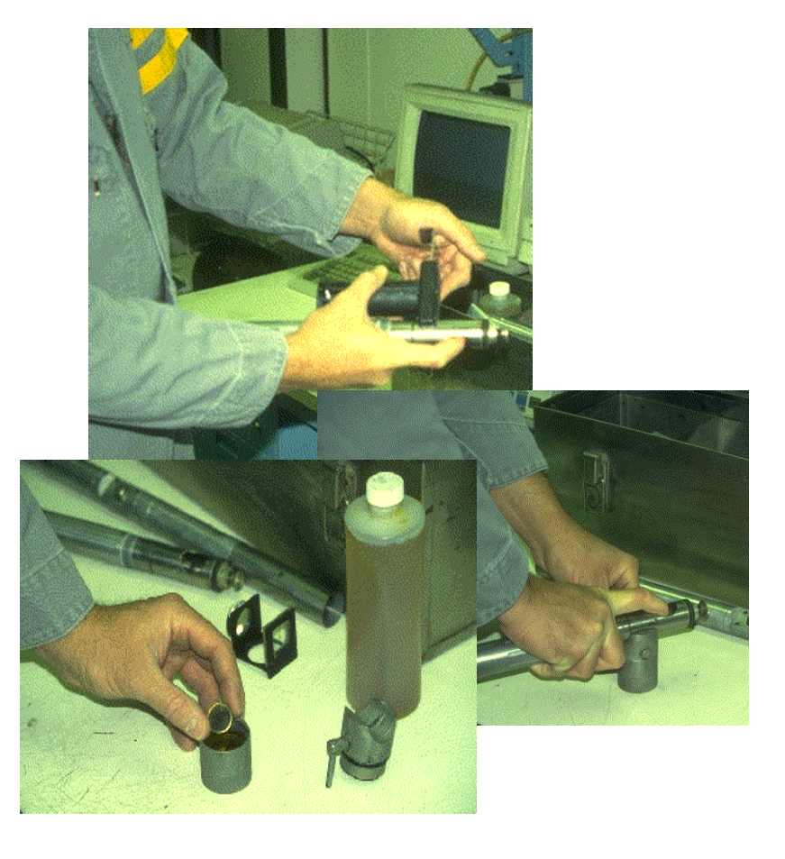
Single-Shot surveys, which photograph the instrument at a single position, are often used by the directional driller to track the drilling bit’s progress while drilling is underway. The compass unit of a magnetic survey instrument is placed in a non-magnetic drill collar (NMDC) to isolate the compass from the drill string’s magnetic interference. Placement of the instrument within the non-magnetic drill collar varies with the wellbore attitude, latitude, and bottom hole assembly.
Magnetic Single Shot Survey Tool Limitations
- Requires non-magnetic drill collars
- Temperature
- Must re-run to confirm changes in toolface
Magnetic Single Shot Components
In general, we can say that this tool instrument consists of 3 sections:
- An angle unit consisting of a magnetic compass and an inclination-measuring device.
- A camera section
- A timing device or motion sensor unit
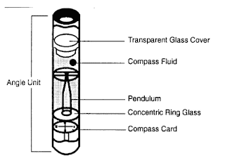
The Angle Unit
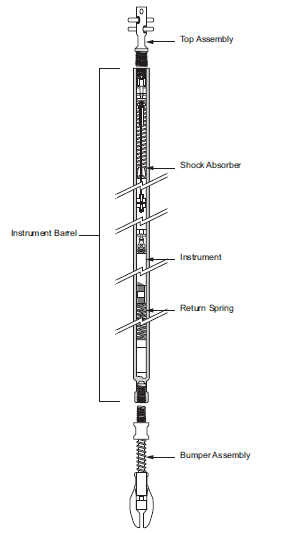
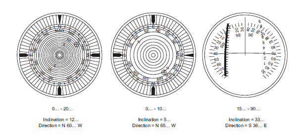
The angle unit of the magnetic single shot survey instrument tool consists of a magnetic compass and a plumb bob (Figures 1, 2 & 3). When the tool is in the correct position near the bit (Check Drilling Bits Types Guide), the compass can rotate until it aligns with the Earth’s magnetic field. The plumb bob hangs vertically, irrespective of how the instrument deviates in the hole.
The Camera
The magnetic single shot survey instrument camera consists of a photographic disc mounted in the tool in a lightproof loading device, a set of bulbs to illuminate the angle unit when required, and a battery unit, which provides power to the light bulbs.
Timing Device
The timing device operates the light bulbs when the instrument is in the correct position. The surveyor must estimate the time required to lower the instrument into position and set the timer accordingly.
Motion Sensor In Magnetic Single Shot Survey Tool
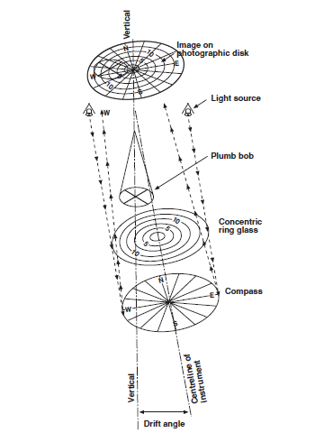
Since estimating the time required for the tool to reach the bit is sometimes tricky, more modern instruments use a Motion sensor unit. This electronic device will illuminate the light bulbs when the instrument stops moving. When the light bulbs are illuminated, a photograph image of the plumb bob is superimposed on the compass card, as shown in Figure 4.
Pre-survey Checklists
An OU representative should ensure that the following is carried out :
- Check that the required length of NMDC is available.
- Check that the instrument landing assembly will sit correctly in the landing ring (TOTCO ring), and will not jam or land eccentrically.
- Check whether the instrument is to be top or bottom landed or used with a mule shoe.
- Install the landing ring in the proper place when making up the BHA. Avoid landing the instrument directly on the bit, mud motor, or turbine. The instrument could get stuck and make it impossible to circulate.
- Check that the instrument will pass the rest of the BHA above the landing ring and not hang up (e.g., in the drilling jar).
- Check that the instrument kit box is complete and the angle units have been checked in the workshop before delivery to the well site. Check that no angle unit has been used more than 25 times after calibration.
Specifically, check that the kit box includes:
• two angle units of each range, which should be used alternately
• batteries specified for the instrument
• film discs
• developing chemicals
and ensure that the film is kept dry before the survey is run. - Check the angle unit in the field test stand. Ensure the angle unit inclination readings agree with the field test stand inclinations.