Oil & Gas Measurement While Drilling systems allow the driller to gather and transmit information from the bottom of the hole back to the surface without interrupting normal drilling operations. This information can include directional deviation data, data related to the petrophysical properties of the formations, and drilling data, such as WOB and torque (check also: torque & drag).
The information is gathered and transmitted to the surface by the relevant sensors and transmission equipment housed in a non-magnetic drill collar in the bottom hole assembly (check also: types of Bottom hole assembly). This tool is known as a Measurement While Drilling Tool. The data is transmitted through the mud column in the drill string to the surface. At the surface, the signal is decoded and presented to the driller appropriately. The transmission system is mud pulse telemetry and involves no wireline operations.
To take a directional survey using conventional wireline methods may take 1-2 hours. Using an MWD system, a survey takes less than 4 minutes. Although MWD operations are more expensive than wireline surveying, an operating company can save valuable rig time, which is usually more significant in cost.
More recently, MWD companies have developed more complicated tools that will provide directional information and drilling parameters (e.g., torque, WOB) and geological data (e.g., gamma-ray, resistivity logs). The latter tools are generally called Logging While Drilling – LWD Tools.
As more sensors are added, the transmission system must be improved, and so MWD tools are becoming more sophisticated. Great improvements have been made over the past few years, and MWD tools are now becoming a standard tool for drilling operations.
MWD Applications
Depending on the level and complexity of the MWD service used, applications include:
- Directional Drilling control
- Relief well drilling
- Bottom hole location
- Casing seat selection
- Gas influx identification
- Lithological identification
- Offset well correlation
- Coring point selection
- Invasion profiling
- Pore pressure analysis
- Precision geosteering in high-angle wells
- Hydrocarbon identification
- Shallow gas control
- Reconnaissance and insurance logging in high-risk wells
- Cost-effective wireline replacement
Where drilling mechanics MWD is used, it may be possible to provide information to aid in the following:
- Drilling optimization & measurement
- Drilling Hydraulics optimization
- Bottom-hole assembly damage avoidance
- Drilling Bit whirl analysis (Bit Whirl)
- Influx monitoring (well kick)
- Swab and surge measurements while tripping pipe (avoiding well kicks or, conversely, formation damage)
Measurement While Drilling System Components
All MWD systems have certain basic similarities, which are as follows:
- A downhole system comprises a power source, sensors, transmitter, and control system.
- A telemetry channel (mud column) through which pulses are sent to the surface.
- A surface system that detects pulses decodes the signal and presents results (numerical display, geological log, etc.).
Check the full article about MWD Tool Components.
Measurement While Drilling Sensors
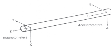
All MWD systems use the same directional sensors for calculating inclination, azimuth, and toolface. The sensor package consists of 3 orthogonal accelerometers and three orthogonal magnetometers.
Accelerometer
An accelerometer measures the component of the earth’s gravitational field along the axis in which it is oriented while drilling. It works on the “force-balance” principle. Atest mass is suspended from a quartz hinge, which restricts movement to one axis only. As the mass tends to move due to gravity acting along that axis, its central position is maintained by an opposing electromagnetic force.
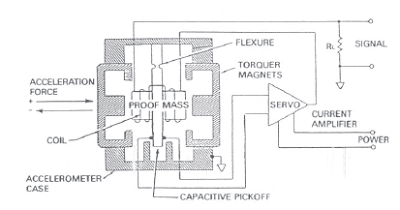
The larger the gravitational force, the larger the pick-up current required to oppose it. The voltage drop over a resistor in the pickup circuit is measured, directly related to the gravitational component. Depending on the orientation of the BHA, the reading on each accelerometer will be different. The angle of inclination and toolface can be calculated from these three components.
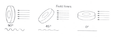
Magnetometer
A magnetometer will measure the components of the Earth’s magnetic field along one axis. If a wire is wrapped around a soft iron core and placed in a magnetic field, the current induced in the pick-up circuit will vary depending on the toroid’s angle. Therefore, the size of the current is related to the direction of the coil concerning the direction of the magnetic field. As with the drilling accelerometer, the voltage measurement is done across a resistor in the pick-up circuit of the magnetometer. The voltages read at each magnetometer can then be used to calculate azimuth.
Sensors Surveying & Calculations
A, b, c, x, y, and z refer to the accelerometer and magnetometer readings with axes in the following equations.
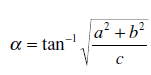
Inclination – the angle between the C accelerometer and the vertical. Looking at a vertical cross-section
.
Toolface – the angle between the high side and B accelerometer. Looking down the tool along the C axis:
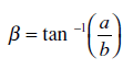
Azimuth – the angle between the Z-axis and magnetic North when projected onto the horizontal plane. Looking in the horizontal plane, we define two vectors, V1 and V2, where V1 lies along the tool axis.
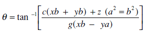
Notice that accelerometer readings are also used in the calculation of azimuth. If there is any mistake in the accelerometer readings, inclination, toolface, and azimuth will all be wrong. Since we rely on the magnetometers responding only to the earth’s magnetic field, any local magnetic effects from the drill string must be isolated. There must be enough non-magnetic drill collars above and below the sensors to stop such interference. As a result, the sensors will be operating 40′ – 80′ behind the bit (the exact distance must be known before the tool is run).
Check the full article about MWD sensors.
Measurement While Drilling Normal Surveying Routine
The usual practice in taking a survey is to drill to the end of the string and make the connection. Run in the hole and tag the bottom. Pick up 5′-10′ and keep the pipe steady for 2 minutes (this allows survey data to be stored). Re-start drilling, and survey data is transmitted to the surface. In some tools, the transmission is initiated by rotation. In others, it senses pump pressure. During the steering (Check also Rotary steerable drilling system) run, where a drilling mud motor is being used an update of the toolface is usually transmitted every minute. This is of great value to the directional driller as he monitors the progress of the well.
Check the full article about Drilling With MWD Operations & Procedures
Accuracy of Measurement While Drilling
MWD companies quote slightly different figures for accuracy but generally within the following limits:
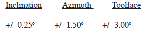
These figures compare favorably with Magnetic single-shot Survey accuracies, and MWD offers the advantage of repeating surveys at the same depth with little loss in rig time.