There is only a small distance between slots on multi-well projects, mainly offshore. To eliminate the risk of collisions directly beneath the platform (platform rigs), a proposed well path is compared to existing and other proposed wells. The distances between other wells and the proposal are calculated frequently in the critical section. These anti-collision calculations in directional drilling operations & travelling cylinder plots can be performed using the applications COMPASS or WELLPLAN.
Survey uncertainty must also be computed for the proposed and critical existing wells. All the major operating companies have established criteria for the minimum acceptable separation of wells, which are usually linked to “cone of error” or “ellipse of uncertainty” calculations. This article will discuss a simple overview of anti-collision for directional drilling.
- The surveys and well plans are used to carefully map the relationship of the proposed new well to all existing wells and any proposed future wells.
- “Spider” Plots are usually of horizontal projection.

Definition Of Travelling Cylinder Plot (TCP).
Traveling Cylinder Plot (TCP) is a collection of tools operators have traditionally used to plan and drill safely through a maze of wells. The most common usage is on wells drilled from offshore rig platforms or wells drilled from land pads with multiple adjacent wells. Their principal usage is in the vertical hole sections near the surface, where collision risks are generally the highest (TCP). It involves imagining a cylinder with a given radius enclosing the wellbore from one depth to another, the zone of interest. Any well entering this cylinder, i.e., approaching closer than the radius of the cylinder to the central well, is plotted and displayed graphically.

Volumes of Uncertainty.
The systems for surveying directional drilling wells have limited accuracy. The survey may also be subject to errors resulting from:
- Downhole changes in the magnetic field.
- Systematic errors associated with either a magnetic or gyro compass (check gyro tool for surveying)
- Misalignment of the tool in the hole
- Depth measurement and inclination.
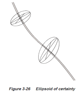
Ellipsoid Of Certainty Plot.
Definition: ellipsoid (3-D body) representing the envelope of the likely position of a given well survey point based on the error.
Lead Angle & Anti Collision in Directional Drilling :
- Drilled with rotary assemblies, directional wells often tend to turn or “walk” during drilling.
- “Lead Angle” where the tendency is anticipated using experience in the same or similar areas and built into the initial directional orientation of the well
- Using steerable systems, while more costly, removes a lot of the guesswork and allows a straighter, more accurate hole.
Well Plan Maps
The vertical projection of the actual well is plotted using the TVD and Vertical Section values from the survey calculations. The Horizontal projection is plotted using the North/South and East/West coordinates.
