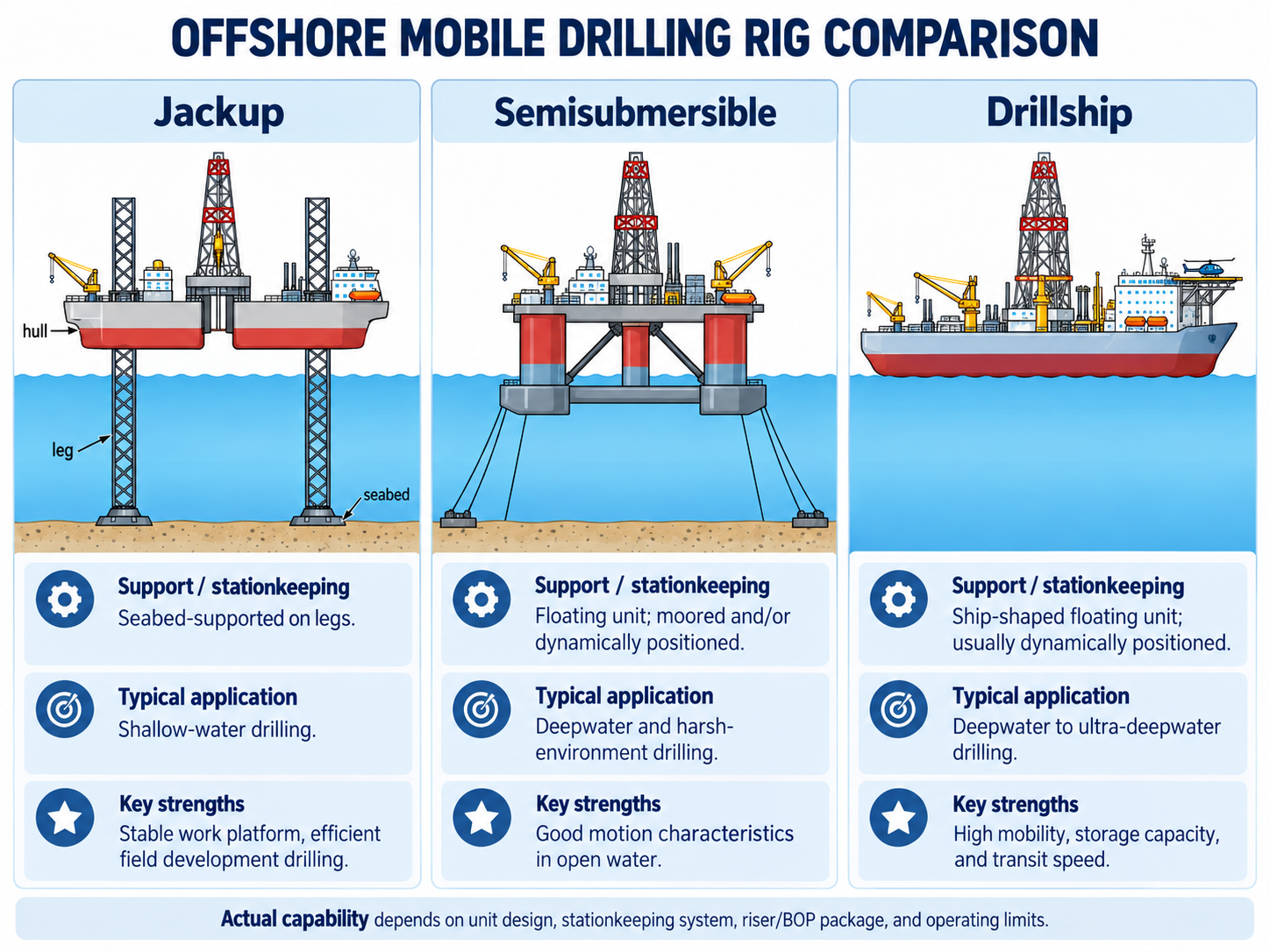
The three main mobile offshore drilling rigs are jackups, semisubmersibles and drillships. Jackups stand on seabed-bearing legs during drilling; semisubmersibles and drillships remain afloat. Platform rigs, tender-assisted arrangements and shallow-water barge or submersible units serve other offshore applications.
This guide compares how each type works, where its advantages matter, and what can disqualify a candidate. It also explains real rig specifications and works through a hypothetical selection case. Engineering explanations draw on the IADC Drilling Manual, 12th edition, Peter Aird’s Deepwater Drilling and the supporting references listed below. The worked cases are original teaching examples, not field results.
Offshore Drilling Rig Types: Quick Comparison
A mobile offshore drilling unit (MODU) may be bottom-supported or floating. Keep support, stationkeeping and drilling arrangement separate: dynamic positioning describes how a vessel holds station, not its hull shape. The general drilling-rig types guide covers the wider land/offshore classification. [4]
| Type | How it works | Best reason to consider it—and key constraint |
|---|---|---|
| Jackup | Legs support an elevated hull on the seabed. | Stable drilling base; foundation behavior, leg reach and cantilever loads must fit the site. |
| Semisubmersible | Submerged pontoons and columns support a floating deck. | Favorable motion response; examine task-specific weather limits, payload and well connection. |
| Drillship | A ship-shaped vessel drills through a moonpool. | Mobility and storage for dispersed campaigns; heading, motions and stationkeeping remain critical. |
| Platform-mounted rig | A drilling package sits on a fixed or floating host. | Development wells from a host installation; deck strength, space and well-center access govern. |
| Tender-assisted system | The host carries the drilling equipment set; a nearby tender carries supporting services. | Reduces the host’s equipment burden; introduces mooring, transfer and connection interfaces. |
| Bottom-founded submersible / posted barge | The unit floats for relocation and rests on the bottom for drilling. | Specialized shallow-water work; draft, bottom conditions and refloating matter. |
| Floating drilling barge | The barge remains afloat and holds station for drilling. | Sheltered-water applications; freeboard, motion and mooring constrain use. |
Jack-Up Offshore Drilling Rigs
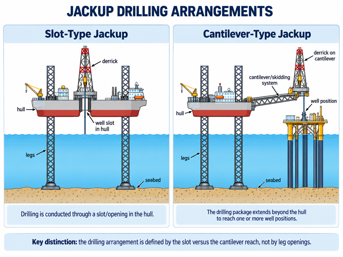
A jackup rig travels afloat, lowers its legs and elevates its hull above the sea. Independent-leg units use separate footings, commonly spudcans; mat-supported units spread support through a connected mat. A slot or cantilever is a different classification describing the drilling package. An independent-leg rig can therefore also be a cantilever rig. [1, 4]
The elevated hull offers a steady drilling base, commonly with surface well-control equipment. A cantilever moves the well center beyond the hull and can serve several positions on a platform grid. That is useful for development drilling and workovers, but both the well-center envelope and the load envelope must cover the intended operation. [4, RT-7–RT-8]
Leg Penetration, Air Gap and Cantilever Reach
Foundation check: soil layering, old spudcan footprints, obstructions and predicted penetration affect the installation. Preloading addresses anticipated footing loads, but a completed preload is not a substitute for the site assessment. The preliminary selection needs the geotechnical evidence and the rig’s proposed loading condition. [1, 2, 4]
Reach check: increasing penetration or the required air gap consumes available leg length. Define the water-level datum consistently. Separately, read the combined hook, setback and other drill-floor load chart at the actual cantilever extension and transverse position. The maximum advertised hook load may not be available there. [1, 2]
The scope of ISO 19905-1:2023, with Amendment 1:2025, concerns elevated site-specific assessment of independent-leg jackups; it does not cover transit, installation or removal. Address those phases in the jackup positioning and rig-move plan. This standards reference supplements the books; it does not certify a candidate.
Semisubmersible Offshore Drilling Rigs
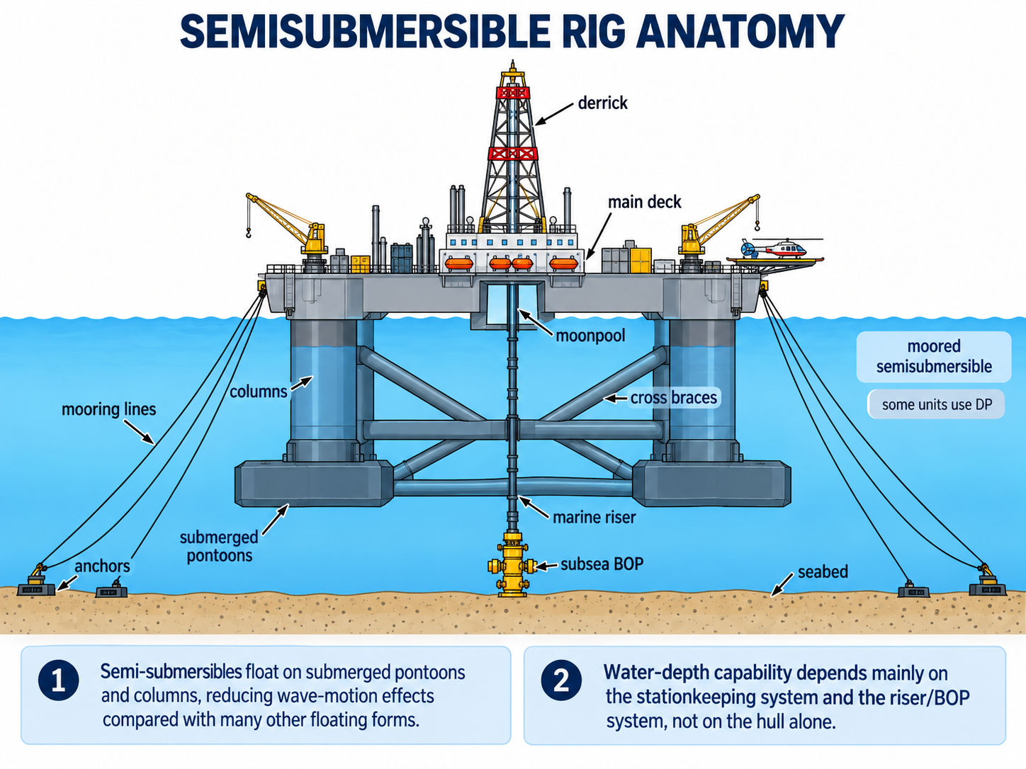
A semisubmersible operates afloat on submerged hulls or pontoons connected to the deck by columns. Ballasting establishes its operating draft. The relatively small waterplane area—the area where the structure intersects the water surface—helps limit wave-induced motions compared with a ship-shaped hull. It still heaves, rolls and pitches. [4, RT-8–RT-9; FD-4]

Its principal attraction is the operating time that favorable motions can make available. That advantage must be checked at the intended draft, headings and wave periods. A semi that can drill comfortably may still face a narrower limit while landing a subsea BOP, transferring cargo or launching an ROV. These tasks need separate operating criteria. [4, FD-4–FD-6; 5, pp. 147–155]
Water Depth: Minimum Clearance and Maximum Capability
Shallower water is not automatically easier for a floater. Lower-hull clearance, seabed and BOP separation, tide, heave, and slip-joint space-out can control its minimum operating depth. At greater depth, additional riser and drillpipe also consume storage and load capacity. [1; 4, RT-9]
Check the complete riser inventory, tensioning and handling capacity, usable fluids capacity, subsea controls and permitted motions. Increasing the length of a mooring system does not increase these other capacities. This is why a depth rating should be read alongside the equipment configuration rather than in isolation. [1, 4]
Moored Semisubmersibles
Semis may use spread moorings, dynamic positioning, or an assessed mooring arrangement with thruster assistance. A moored option requires an anchor and line layout compatible with the seabed, nearby infrastructure and operating offsets. A DP option instead needs the appropriate power, thrust, reference systems and failure assessment. [4, FD-18–FD-19]
Drillships
A drillship carries its drilling system in a self-propelled, ship-shaped hull, usually with a central moonpool. Transit capability and substantial storage can make it attractive for remote exploration or a campaign spread between locations. IADC contrasts that logistical strength with the generally more favorable motions of a semisubmersible. The actual pair of vessels still requires comparison. [4, FD-4–FD-5]
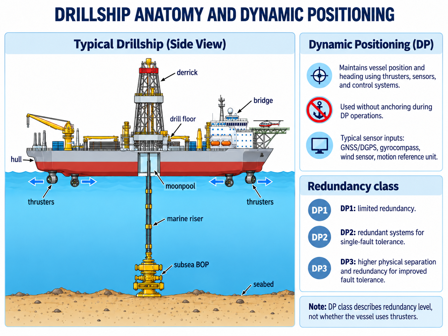
Heading affects the ship’s response to wind and waves. DP can allow a change of heading while maintaining position, whereas a fixed spread mooring constrains that freedom. However, the usable heading must also respect the riser, environmental loads and operating configuration. Neither propulsion nor a large storage capacity eliminates marine support and resupply needs. [1, 4]
Offline Handling and Dual Activity: Compare the Actual Sequence
Extra work centers can move some tubular preparation and equipment handling away from the main drilling sequence. IADC describes longer riser joints, offline handling and separate fluid systems as ways to reduce connections or changeover work. These are equipment-and-process advantages, not automatic savings assigned to every drillship. [4, RT-10]
Ask which task can run in parallel, which crew and equipment it needs, and whether it still competes for cranes, handling routes, power or the well center. Compare casing preparation, tripping, riser handling and BOP deployment as well as rate of penetration. Aird specifically includes these non-drilling activities in vessel selection. [5, pp. 190–191]
Platforms: Drilling Package Versus Host Structure
A platform drilling rig is equipment carried by an engineered host. Steel jackets, gravity-based structures and compliant towers transmit loads to seabed foundations in different ways. A buoyant host has a different load path. A tension-leg platform is floating: tensioned tendons restrain its buoyant hull; it is not a jackup standing on legs. [4, RT-3–RT-4]
The public MIT tension-leg-platform design study also explains buoyancy and tendon restraint. A production host, including an FPSO, should not be assumed to have drilling capability simply because it supports offshore processing equipment.

Platform Costs and Installation Timing
Assess deck reactions, beam spacing, module weights, crane reach, well-center access and production interfaces. Modular packages can help fit constrained decks, but every lift and support point must match the host. Compare installation, removal, modifications and production conflicts alongside the daily rig rate. [1]
The rig-move plan should connect package dimensions and lifting arrangements to the transport and installation sequence. That turns a general claim of “easy mobilization” into a reviewable scope.
Tender-Assist Offshore Drilling Rigs
A tender-assisted arrangement places the drilling equipment set on the host while a nearby vessel carries supporting services, storage and accommodation. IADC describes how this addresses a host that cannot carry the entire drilling package and its supplies. [4, RT-3–RT-4]
A barge or semisubmersible tender adds its own motion, mooring and transfer requirements. Check flexible service connections, personnel access, cargo transfers and adverse-weather arrangements together. The tender-assisted drilling guide explains the equipment split. Reduced host weight does not remove these interfaces. [1, 4]
Submersibles: Bottom-Supported Offshore Drilling Rigs
A bottom-founded submersible floats for relocation, then rests its lower structure on the seabed during drilling. Posted barges are another shallow-water arrangement described by IADC. They differ from a semisubmersible, which normally drills afloat. [4, RT-6–RT-7]
Selection requires a usable tow route, sufficient draft clearance, suitable bottom conditions and a workable refloating plan. Seabed support removes normal floating motion during drilling, but weather, sliding and foundation risks remain. [1]
Drilling Barges
Barge identifies hull form rather than a single support mechanism. Some units work afloat; others are bottom-founded. For an afloat unit, freeboard, motion, mooring and the well connection matter. For a grounded unit, add foundation and refloating checks. Historical sheltered-water examples illustrate this distinction without establishing present-day geographic or depth limits. [1, 3, 4]

Reading Rig Specifications: Designed, Outfitted and Assessed
Water depth is the water-column dimension; drilling depth is a separate well/drilling-system capability. Designed capability describes a design basis, while outfitted capability depends on installed equipment. Site assessment then tests the proposed unit, configuration and operation against local conditions. [1, 4, 5]
The following public examples are separate from the book-derived explanations and the hypothetical case below. They illustrate what to read in a specification, not a common bid basis or a recommendation of available rigs.
| Named example and source | Published information | What the reader should establish |
|---|---|---|
| Noble Invincible — jackup | Water depth: 492 ft; leg length: 675 ft; cantilever envelope: 110 × 73 ft. | Use the site assessment and combined load chart. Reach and individual load ratings are not simultaneous-load approval. |
| Deepsea Atlantic — semisubmersible | Designed water depth up to 3,000 m; dual derrick and active heave-compensating drawworks. | Check what the auxiliary work center can do during the planned main-well activity. |
| Deepwater Atlas — drillship | 12 July 2024 sheet: 12,000 ft designed and 8,000 ft outfitted water depth; 40,000 ft maximum drilling depth. | Separate design potential, fitted equipment and drilling-depth capability. Confirm any later configuration changes. |
Mooring Versus Dynamic Positioning
Floating units must remain within the position and heading limits of the connected drilling system. IADC describes DP as an integrated arrangement of power, thrusters, position/heading references, sensors and controls. Kongsberg’s DP overview provides a supplementary public explanation. [4, FD-18–FD-19]
| Method | Stationkeeping mechanism | Evidence needed |
|---|---|---|
| Spread mooring | Anchor-line restoring forces; thruster assistance where assessed. | Line and anchor assessment, seabed layout, offsets, deployment and degraded cases. |
| Dynamic positioning | Controlled propulsion counters forces on the vessel. | Power/thrust capability, reference-system integrity, failure analysis and trials. |
| Assisted arrangement | Approved coordination of moorings and propulsion. | The assessed operating mode and available capability after specified failures. |
Conventionally Moored Drillships
Spread moorings restrict a ship’s freedom to turn into changing weather. Evaluate heading, wave period and beam-sea response together with anchor and line loads. A mooring footprint that conflicts with pipelines or other installations can eliminate an otherwise capable candidate. Line counts and dimensions belong to the actual design. [1, 4]
Turret-Moored Drillships
A turret allows the vessel to change heading around its mooring connection. Historical drillships used it to address heading-related motion, with constraints in the turret, equipment layout and drilling interfaces. The useful lesson is the relationship between mooring geometry and usable heading, rather than a historical fleet count. [1, 3]

Why Holding Position May Reduce Drilling Power
Installed generator power is not all available for drilling. Thrusters, drilling equipment and accommodation/auxiliary services share the generation and distribution system. IADC describes a power-management response that can reduce drilling demand when the vessel needs more power for stationkeeping. [4, FD-8, FD-18–FD-19]
For selection, request the simultaneous-load balance for the proposed operating mode and specified failures. Check whether the planned pumping, hoisting and other work can continue while stationkeeping retains its required capability. A rig can hold position yet lose the ability to perform the intended combination of drilling tasks; this is an engineering implication of the shared power system, not a blanket limit for DP rigs.
Floating Drilling Systems: Riser, BOP and Motion Compensation
Conventional floating drilling commonly connects a marine drilling riser to a subsea BOP and wellhead. The BOP arrangement and its control system provide the specified well-control functions. Surface-BOP floating alternatives have a different configuration; they must be assessed on that basis. [4, FD-1; 5, pp. 185–186]
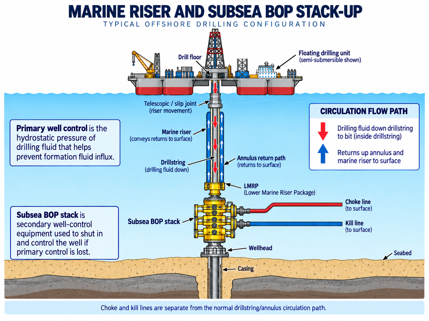
- Riser: provides an access and returns path between rig and subsea equipment.
- Riser tensioning and telescopic joint: manage tension and relative vertical travel in the connected system.
- Drillstring heave compensation: addresses motion transmitted into the drillstring and changes in bit loading.
- Stationkeeping: controls horizontal position and heading; it does not remove heave.
These functions interact but are not interchangeable. Vessel offset, current profile and motions affect riser shape, flex-joint angles and available stroke. Aird discusses drift-off analysis and the time needed to disconnect before the connected system reaches its limits. Use a coupled assessment rather than a generic offset percentage. [1; 5, pp. 147–153]
The illustrated rig-components guide explains the individual systems. Selection must also check their handling routes, load paths and compatibility as an assembled installation.
Weather Operability: Compare Tasks, Not One Wave Limit
A single “harsh-environment” label does not describe the whole campaign. Aird’s well-specific operating-guideline example assigns different limits to drilling, casing running, BOP landing, cargo handling and other tasks. The numerical limits belong to that cited example, but the distinction is directly useful when comparing candidates. [5, Table 4.8, p. 151]
Compare predicted vessel motion at the intended draft and headings with the limits of each critical task. Then consider how long the task needs acceptable conditions, including preparation and safe recovery. A short window that permits drilling may be inadequate for an equipment deployment that cannot be paused at every stage. IADC separately stresses integrating forecasts with operations. [4, FD-60; 5, Chapter 4]
A Historical Lesson: Losses Outside the Main Drilling Interval
Aird reports that more than 70% of operating lost time in a 21-well North Atlantic study from 1993–1996 occurred in the top-hole, surface and abandonment phases. The book attributes the study to Kingdom Drilling. This is a reported historical finding, not a new dataset or a forecast for today’s fleet. [5, p. 154, Figure 4.23]
Selection implication: investigate riser/BOP handling, tubular operations and the beginning and end of the well—not only drilling rate in the reservoir. Aird also notes the absence of a direct drillship-versus-semisubmersible operating study in the regional discussion that follows. The historical observations therefore do not prove that one hull type always wins. [5, p. 155]
Selecting Offshore Drilling Rigs for the Actual Well
Begin with the well plan, site evidence and operating season. IADC identifies the rig-family and equipment differences; Aird connects them to scope definition, inspection, contractor capability and intake. A practical sequence is screen technical mismatches, resolve uncertainties, then compare commercial alternatives. [4, 5]
| Selection question | Evidence to obtain | Mismatch the evidence can reveal |
|---|---|---|
| Can it occupy the site? | Bathymetry, foundation or anchor data, infrastructure map and approach route. | Adequate headline depth rating, but incompatible seabed, draft or anchor footprint. |
| Can it perform the critical tasks? | Task-specific motion limits, metocean study, handling sequence and recovery windows. | Drilling is possible, but BOP landing, casing or cargo transfer controls downtime. |
| Can it carry the loads where required? | Combined cantilever/skid load chart, deck-load plan and crane charts. | Published maximum unavailable at the actual position, draft or lift radius. |
| Does the installed package fit? | Pumping and hoisting duties, power balance, BOP/ROV interfaces, riser and tensioning capacity. | A subsystem or shared resource restricts the planned operation. |
| Can it support the full campaign? | Usable fluid/bulk capacity, storage layout, supplies, maintenance and personnel arrangements. | Capacity or support frequency is insufficient for the planned sequence. |
| Is it demonstrably ready? | Equipment condition, maintenance and test records, competence evidence and closed-out deficiencies. | The specification fits on paper, but delivered readiness remains unproven. |
From Shortlist to Readiness to Drill
Aird separates preliminary selection from more detailed inspection and acceptance. The bid starts the review; it does not finish it. Turn each unresolved issue into an evidence requirement, an accountable person and a completion point before the affected operation. [5, pp. 188–193, 401–405]
- Equipment: reconcile the proposed configuration with inspection, maintenance and relevant function-test records.
- Interfaces: verify the planned BOP, wellhead, riser, handling and third-party equipment combinations.
- Operations: agree the task sequence, constraints, contingencies and marine/drilling responsibilities.
- People: establish that assigned crews and specialists can execute the work and its contingencies.
- Close-out: record how and when each deficiency is resolved, including changes affecting the agreed scope.
Use the rig acceptance and commissioning review to carry these requirements into intake. The list above is an editorial synthesis of the cited planning principles, not a replacement for the contractor’s acceptance program.
Worked Example: Jackup Leg Reach and a Three-Candidate Screen
Hypothetical teaching case. Assume a remote exploration location with a 95 m water-depth requirement on the adopted water-level basis, no host platform, and three fictional bids: Jackup A, Moored Semi B and DP Drillship C. These are not the named rigs in the specification table. All numerical inputs below are invented for the example.
For Jackup A, apply ENI’s simplified relationship: D = T − (Z + J + A + P). D is available depth on that same basis, T leg length, Z reserved upper-leg length, J hull/jackhouse allowance, A air gap and P penetration. [2]
| Term | Meaning | Assumed value |
|---|---|---|
| T | Total leg length | 150 m |
| Z | Upper-leg reserve | 5 m |
| J | Hull/jackhouse allowance | 10 m |
| A | Air gap on the selected datum | 20 m |
| P | Initial penetration assumption | 15 m |
| D | 150 − (5 + 10 + 20 + 15) | 100 m |
Step 1: Test the Assumption That Could Change the Shortlist
At 15 m penetration, the remaining geometric allowance is 100 − 95 = 5 m. At an assumed adverse penetration of 25 m, D becomes 90 m: a 5 m shortfall. The first result therefore does not support acceptance across the assumed penetration range. Neither calculation evaluates footing capacity, leg strength, jacking or environmental loads.
| Bid | Assumed screening evidence | Decision within this example |
|---|---|---|
| A | 100 m geometric allowance initially, falling to 90 m at adverse penetration. | Hold out of the cost comparison until geotechnical assessment resolves the range or another assessed configuration meets the requirement. |
| B | Assume its specific shallow-water clearance, anchor layout, riser, task envelopes and drilling package have passed the project checks. | Retain for commercial comparison under those assumptions. |
| C | Assume its specific shallow-water clearance, DP/power, riser, task envelopes and drilling package have passed the project checks. | Retain for commercial comparison under those assumptions. |
The wellhead/BOP architecture and operating sequence must also suit each candidate. There is no host for a platform rig or tender-assisted package in this assumed scope. Changing the location, scope or evidence could change the shortlist; price does not close a technical shortfall.
Step 2: Compare Campaign Cost After Technical Screening
For the two assumed acceptable floaters, use a simple comparison: C = F + R × (B + W). F is the specified fixed campaign allowance, R the daily hire rate, B candidate-specific base days, and W additional weather-delay days. Base days exclude W. Different base durations are assumptions, not a claim that a drillship always completes a well faster.
| Assumed input / result | Semi B | Drillship C |
|---|---|---|
| Daily hire rate R (US$/day) | 300,000 | 350,000 |
| Base operating duration B | 55 days | 48 days |
| Additional weather delay W | 6 days | 12 days |
| Fixed campaign allowance F | US$4.0 million | US$2.0 million |
| Chargeable days B + W | 61 days | 60 days |
| Hire plus specified allowance | 4.0 + 0.300 × 61 | 2.0 + 0.350 × 60 |
| Comparison cost C | US$22.30 million | US$23.00 million |
Step 3: Find the Weather-Delay Break-Even Point
Hold Semi B’s assumptions fixed. Drillship C reaches the same comparison cost when 2.0 + 0.350 × (48 + W) = 22.30, giving W = 10 days. At 12 weather days it is US$0.70 million higher; at 5 days its cost falls to US$20.55 million, US$1.75 million lower than Semi B.
The decision turns on evidence for delay and execution time, not a universal hull preference. Before using such a model, replace the teaching inputs with candidate-specific schedules, task-based metocean analysis and contractual costs. Aird’s treatment of lost time and normalized technical/commercial bids supports that approach; the arithmetic and fictional inputs here are our own. [5, pp. 153–155, 193]
Historical Semisubmersible Generations
Generation labels describe successive design developments, but upgrades blur their boundaries. The four early stages below provide historical context rather than a complete list of today’s rigs. IADC and Aird also describe later deepwater developments involving payload, power, motion compensation and offline handling. Compare installed systems instead of assuming a standard equipment package from the generation alone. [1, 3, 4, 5]
The First Generation: Early Floating Adaptations
Some early units adapted submersible-derived designs to floating work. Motion compensation and riser support evolved as the industry gained operating experience. [3]
The Second Generation: Integrated Floating-Drilling Systems
Subsequent designs integrated improved heave compensation, riser tensioning, deck capacity and mobility. These developments widened the range of operations that floating units could perform. [3]
The Third Generation: Greater Loads and Capability
Additional payload and drilling capability required changes to displacement, columns and deck loading. Increasing carrying capacity could also change motion response, creating design trade-offs. [3]
The Fourth Generation: Further Development and Upgrades
Further new builds and upgrades extended environmental service, handling mechanization and water-depth capability. Later generations continued this progression; the applicable specification is the individual rig’s documented configuration. [1, 3, 4, 5]
Offshore Drilling Rig Questions and Answers
What are the three main mobile offshore drilling rig types?
Jackups, semisubmersibles and drillships. Jackups bear on the seabed while drilling; the other two normally work afloat. Platform rigs, tenders and specialized shallow-water units add further offshore arrangements. [4]
Does a semisubmersible rig sit on the seabed?
Normally, no. Its pontoons and columns provide buoyancy. A bottom-founded submersible is different. Anchors holding a floating semi on location do not make its drilling support bottom-founded. [4]
Is a rig’s maximum water depth sufficient for selection?
No. Check the installed configuration, local foundation or stationkeeping assessment, equipment loads, task-specific environment limits and the well connection. Water depth and maximum drilling depth also describe different capabilities. [1, 4, 5]
Technical References and Scope
[1] Mark A. Childers, “Offshore Drilling Units,” Chapter 14, in Robert F. Mitchell (ed.), Petroleum Engineering Handbook, Volume II: Drilling Engineering, SPE, 2006. Relevant sections: 14.3.2–14.3.6, 14.4.3 and rig selection; printed II-606–II-616, II-624–II-629 and II-640–II-641.
[2] ENI Corporate University, Drilling Rigs — Libya ENABV Training Project, document IPE044-E-P-A01, Rev. 001, cover date printed 10/11/2006; Chapter 44, pp. 443–449. Source of the simplified leg-reach relationship and site/penetration considerations.
[3] OffShore rigs, supplied training handout, pp. 19–24; author and edition not established. Used only for historical arrangements and early-generation development, not current fleet or depth limits.
[4] International Association of Drilling Contractors, IADC Drilling Manual, 12th edition, first printing, March 2015. “Types of Drilling Rigs” (RT), pp. RT-3–RT-10; “Floating Drilling Equipment and Operations” (FD), pp. FD-4–FD-8, FD-18–FD-19 and FD-60. Used for rig-family distinctions, payload/motion trade-offs, handling, shared power, stationkeeping and operational planning.
[5] Peter Aird, Deepwater Drilling: Well Planning, Design, Engineering, Operations, and Technology Application, Gulf Professional Publishing/Elsevier, 2019, ISBN 978-0-08-102282-5. Chapter 4, pp. 147–155; Chapter 5, pp. 188–193 and surface-BOP discussion pp. 185–186; Chapter 11, pp. 401–405. Historical studies and example limits retain their original scope.
Supplementary public evidence: the linked ISO pages, MIT TLP study and Kongsberg overview support the identified explanations. Noble, Odfjell and Transocean provide the separately labeled equipment examples. The Atlas sheet is the 12 July 2024 revision; webpage examples were read on 16 October 2026. None establishes current availability or site approval.
Engineering scope: the comparison frameworks and hypothetical calculations are educational analysis, not foundation design, a certified rig selection or a marine/well-control procedure. Actual operation requires the site-specific assessments, agreed program and documentation for the installed equipment. Book figures, proprietary operating tables and field procedures have not been reproduced.
1 thought on “Offshore Drilling Rigs: Types, Uses & Selection”