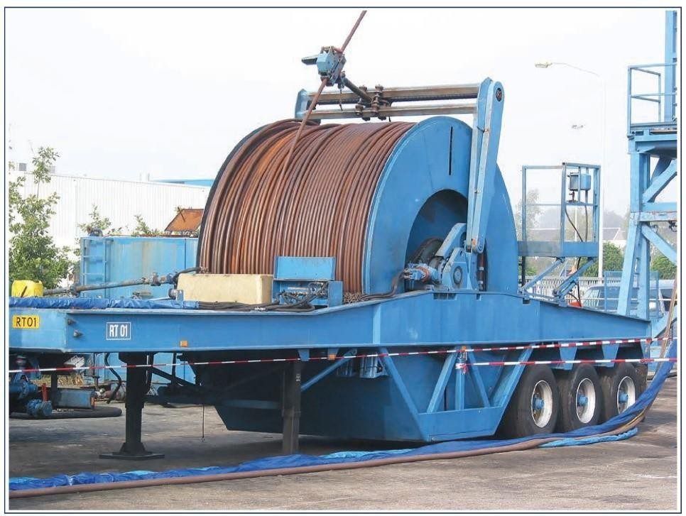
Coiled tubing is stored on large reels in the same manner as the flexible cable of a wireline unit. It is in essence a storage drum, designed to store the entire tubing string, and is an integral part of the CT Unit. These reel’s capacities come in sizes ranging from approximately 5000 to 25000 feet. The weight of the reel increases considerably with longer, larger diameter tubing. Example Reel Weights:
- Reel Without Tubing, 4080 kg (9000 lbs)
- Reel with 6400m or 21,000ft 11∕4″ Tubing, 14,970 kg (33,000 lbs)
- Reel with 4570m or 15,000ft 11∕2″ Tubing, 16,330 kg (36,000 lbs)
Coiled Tubing Reel Components & Functions
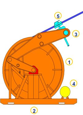
Typical reel components, shown in Figure 1, are as follows:
- Storing and protecting the CT string (drum)
- Maintaining proper tension between reel and injector head (reel drive system)
- Efficiently spooling the CT string onto the reel drum (level wind system)
- Circulating fluids with the drum rotating (swivel)
- Application of protective coating or inhibitor on tubing string (tubing lubricator system)
- Back-up depth measurement (reel mounted counter)
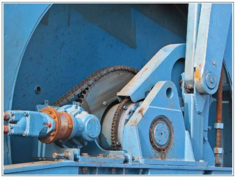
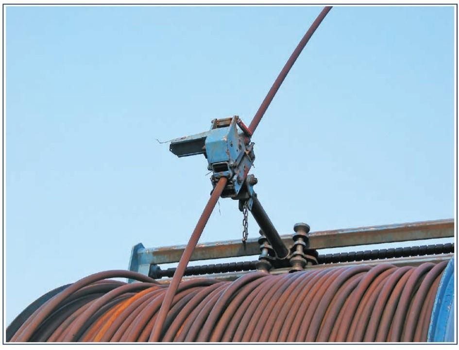
“Levelwind” System (Figure 2) Components include:
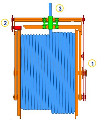
- Drive chain/system (1)
- Override motor (2)
- Spooling head (3)
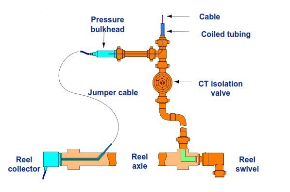
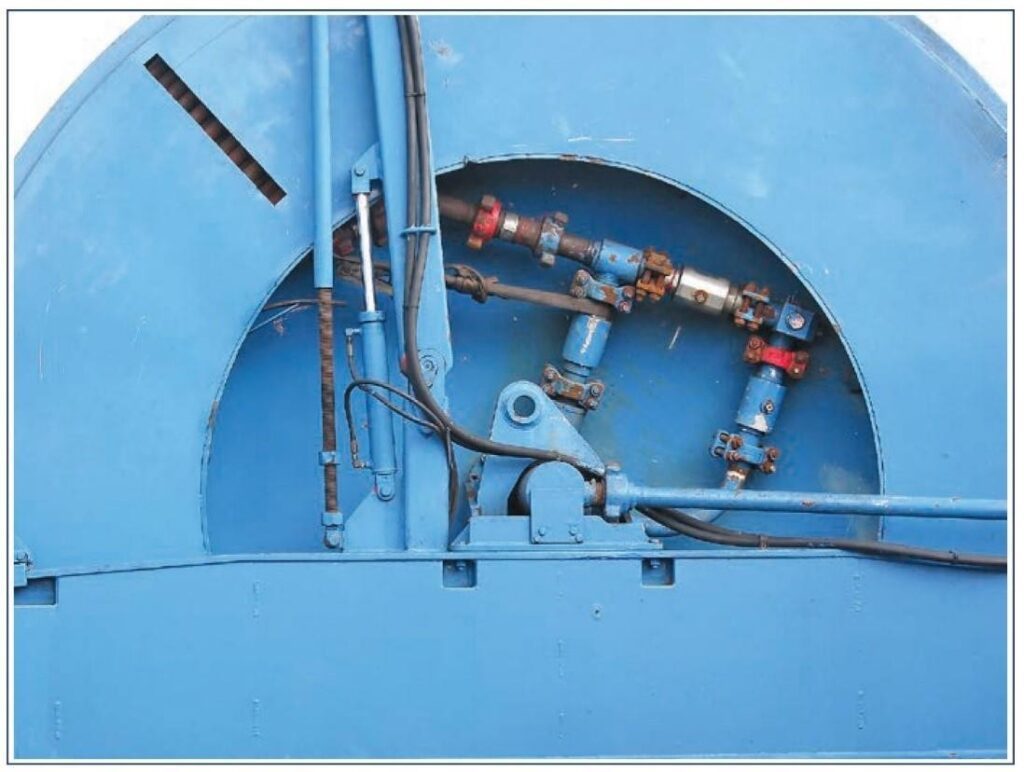
Reel Swivel is mainly used on CT, with one end connected to coiled tubing, and another end to the surface manifold for pressurized rotary operation, as shown in Figure 3:
Mechanism & Working Principal
The reel is supported on an axle and is rotated by a hydraulic motor through a chain drive. This drive system has a dual function: when uncoiling tubing, i.e. running into the well, the motor acts as a constant-torque brake, thus keeping the tubing to the gooseneck under tension.
When coiling, this drive system revolves the reel so as to coil the tubing under constant tension. The CT reel drive system itself is not used to lower or hoist tubing in the well, which is the purpose of the injector head.
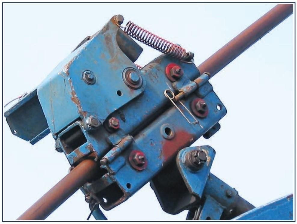
To control the coiling process so that the tubing is correctly coiled upon itself, a winding (spooling) mechanism is synchronized with the rotation of the reel. This is provided with a manual override facility for finer adjustment.
The inner end of the coiled tubing is connected to the hub of the reel which incorporates a rotating joint. Fluid can be pumped through this joint and down the coiled tubing while the reel is stationary or in motion, and to any pressure up to the operating pressure of the coiled tubing itself.
Usually, two depth odometers (both mounted on the spooling arm) are used. Their measuring wheels are rotated by frictional contact with the tubing as it passes by. It is essential that they are mounted correctly so that the spring forces which keep the counter wheel in contact with the tubing are working in the right direction. Finally, a spray system operated from the control skid coats the CT with an oil-based corrosion inhibitor to ensure long life.
In emergency situations i.e. tubing part between the gooseneck and reel, the reel drum will be able to rotate at a far greater speed than normal, therefore it will have to be brought under control immediately. This is done by selecting the reel control lever into the “neutral position”. Once in this position, the directional valve hydraulically locks the motor instantly. However, due to the large amount of inertia caused by the reel drum rotating, it will start to “drive” the reel motor, giving a pump-like characteristic. This will cause a large build-up in hydraulic pressure within the system, and could, if left to build up, rupture a hose rendering the reel unserviceable. To prevent this, a crossflow relief valve is installed.
The size of the reel varies depending on the diameter and length of coil tubing to be stored. Table 1 provides a typical range of reeled units available from coiled tubing service companies:
| Description | Trailer Mounted 1-inch OD. TBG | Truck Mounted 1-inch OD. TBG | Trailer Mounted 1-inch OD. TBG | Skid/ Trailer Mounted 1 1∕2-inch OD. TBG | DNV Certified Skid/ Trailer Mounted 1 1∕4-inch OD. TBG | DNV Certified Skid/ Trailer Mounted 1 1∕2-inch OD. TBG |
| Engine (HP) | 140 | 320* | 280 | 280 | 228 | 228 |
| Reel Capacity | 5334m (17,500 ft) | 4267m (14,000) | 4572m† (15,000) | 4572m (15,000 ft) | 5334m (17,500 ft) | 4572 m (15,000 ft) |
| Reel Speed | 48.8m/min (160 ft/min) | 67.1m/min (220 ft/min) | 48.8 m/min (160 ft/min) | 67.1m/min (220 ft/min) | 67.1m/min (220 ft/min) | 67.1m/min (220 ft/min) |
| Injector Capability (Push/Pull) | 5448 kg 12,000 lbs | 5448 kg 12,000 lbs | 10,896 kg 24,000 lbs | 10,896 kg 24,000 lbs | 10,896 kg 24,000 lbs | 10,896 kg 24,000 lbs |
| Max Working Pressure | 345 bar ** (5,000 psi**) | 345 bar ** (5,000 psi**) | 345 bar ** (5,000 psi**) | 345 bar ** (5,000 psi**) | 690 bar # (10,000 psi #) | 345 bar ** (5,000 psi**) |
| Max Working Pressure | STD/H2S | STD/H2S | STD/H2S | STD/H2S | STD/H2S | STD/H2S |
- * Truck Engine Used as Prime Mover
- ** 790 bar (10,000 psi)
- † Units available with 5334m (17,500 ft) reel capacity
- # DNV units equipped with 790 bar (10,000 psi) Blowout Preventers
Coiled Tubing Reel Drum Capacity Calculations
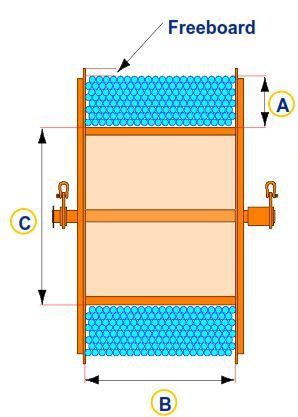
The capacity of the coiled tubing reel drum is calculated through:
L = (A + C) (A) (B) (K)
Where:
- L = Reel capacity (ft)
- A = Tubing stack height (in.)
- B = Drum width (in.)
- C = Core diameter (in.)
- K = Constant (tubing size dependent)
- At tubing size 1-1/4, K= 0.168
- For tubing size 1-1/2, K= 0.116
- At tubing size 1-3/4, K= 0.086
- For tubing size 2, K= 0.066
- At tubing size 2-3/8, K= 0.046