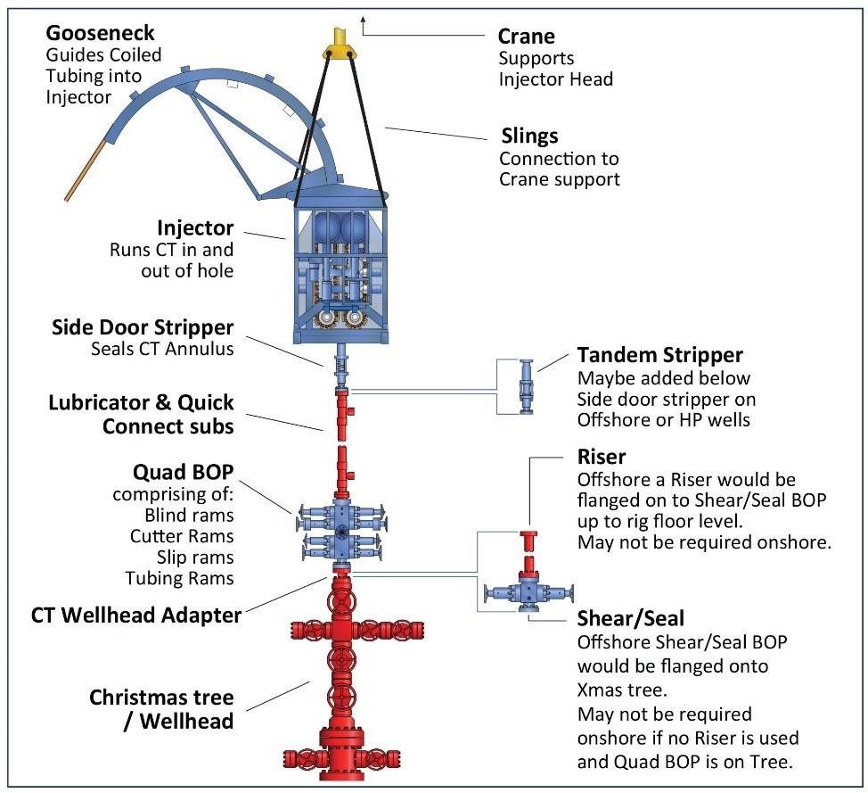
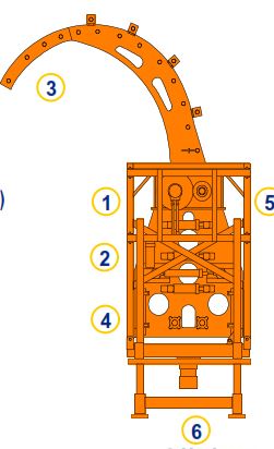
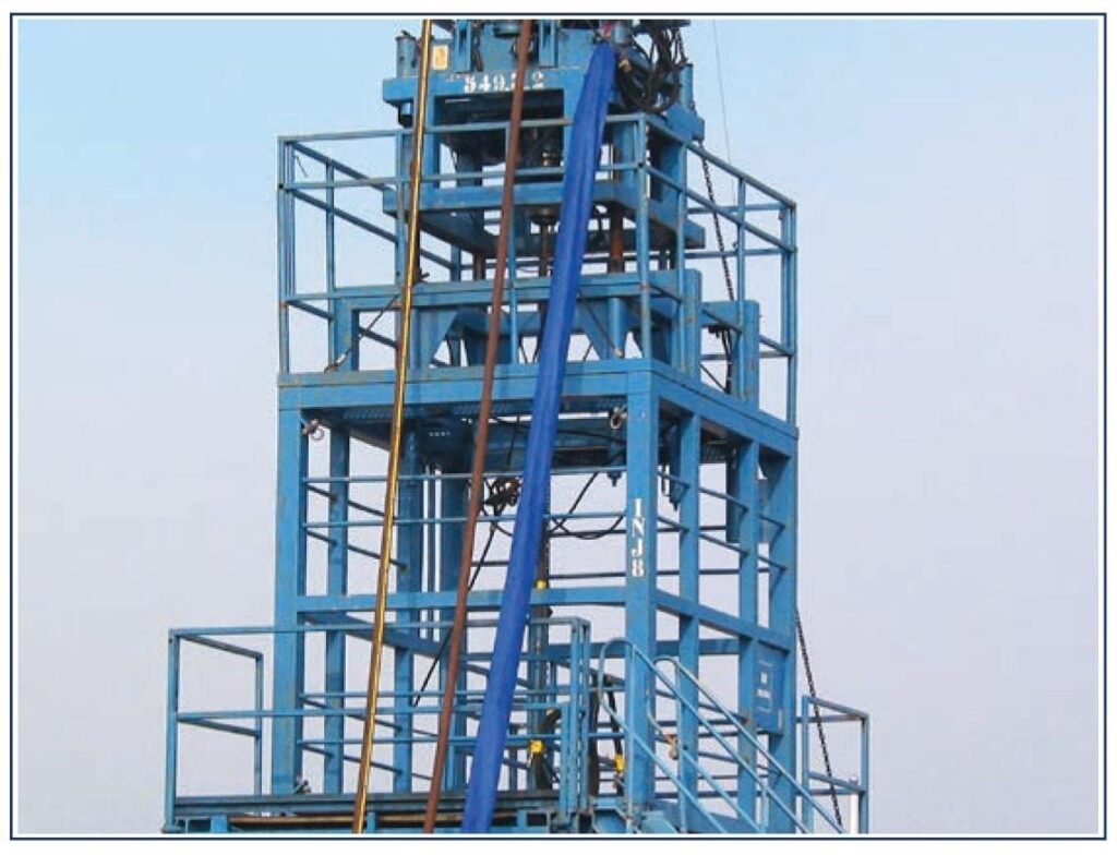
The injector head is the mechanism that transfers the force necessary to inject, retract or hold the coiled tubing with precision control while tripping into/out of the well (check pipe tripping guide). It is the main item in the coiled tubing unit and comprises the following two parts:
- The Injector Drive
- The Tubing Guide (Gooseneck)
A Weight Indicator and Stripper / Packer are usually bolted to the injector subframe, directly underneath the drive chains.
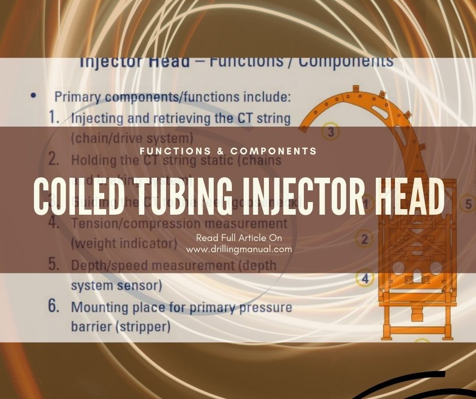
Injector Head Components Functions In Coiled Tubing
- Injecting and retrieving the CT string (chain/drive system)
- Holding the CT string static (chains and braking system)
- Guiding the CT to the Coiled Tubing reel (gooseneck)
- Tension/compression measurement (weight indicator)
- Depth/speed measurement (depth system sensor)
- Mounting place for primary pressure barrier (stripper)
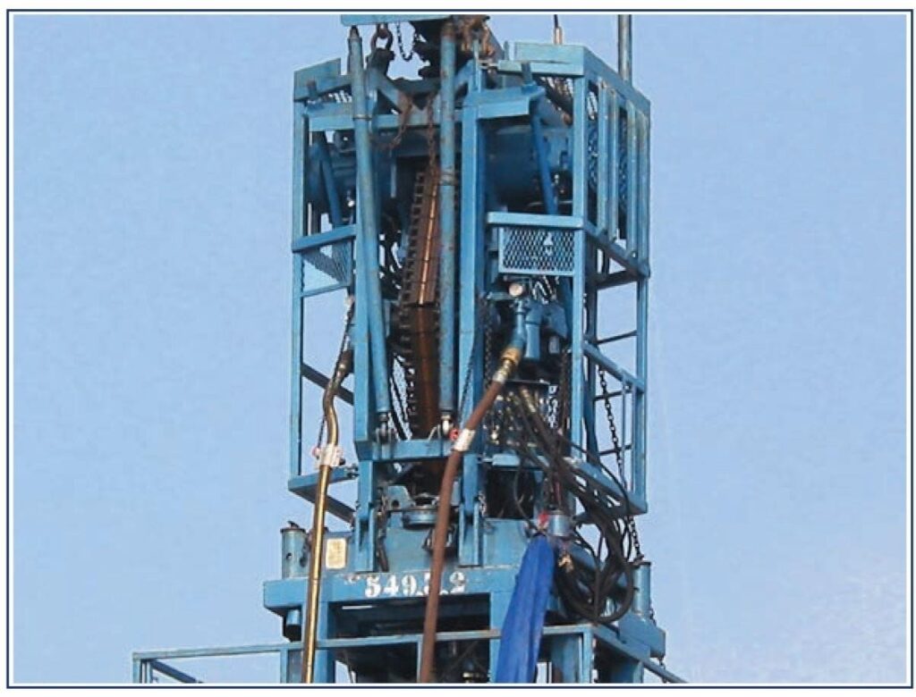
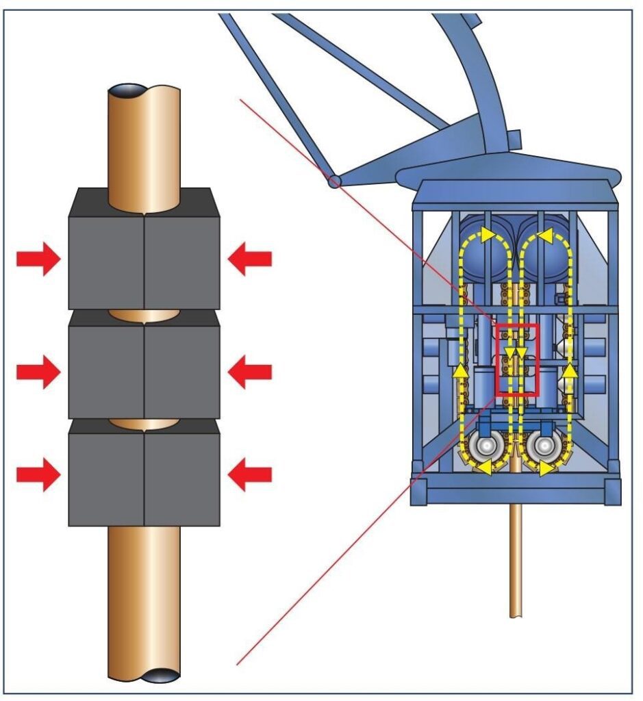
Chain & Gripper Blocks
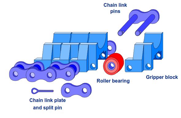
The Injector Head grips the coiled tubing between profiled gripper blocks (sized for the tubing diameter) mounted on triplex chains which are hydraulically driven by two motors. Effectively, the chains grip the tubing, the motors drive the chains.
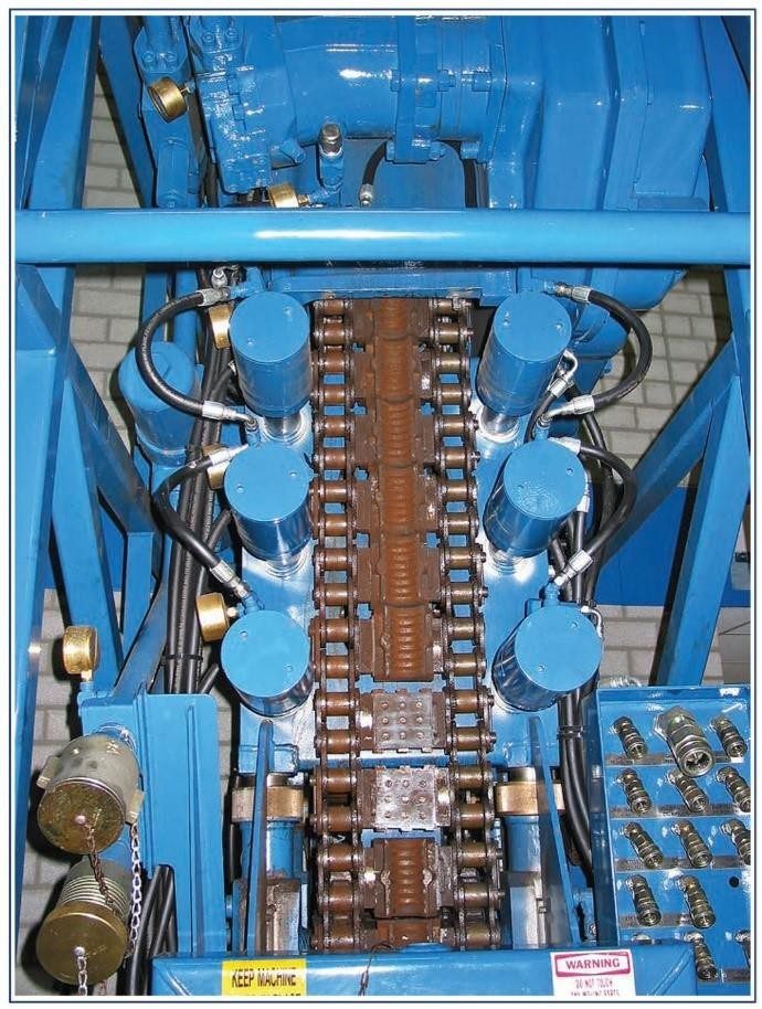
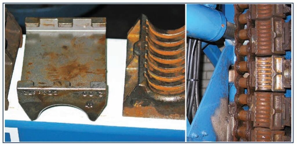
Hydraulic tensioning mechanisms maintain correct tension on the drive chains to prevent crushing or slippage of the tubing. The gripper blocks are pushed against the tubing by hydraulic pistons, and the tubing is generally “held” by at least 2 pairs of gripper blocks are holding the tubing.
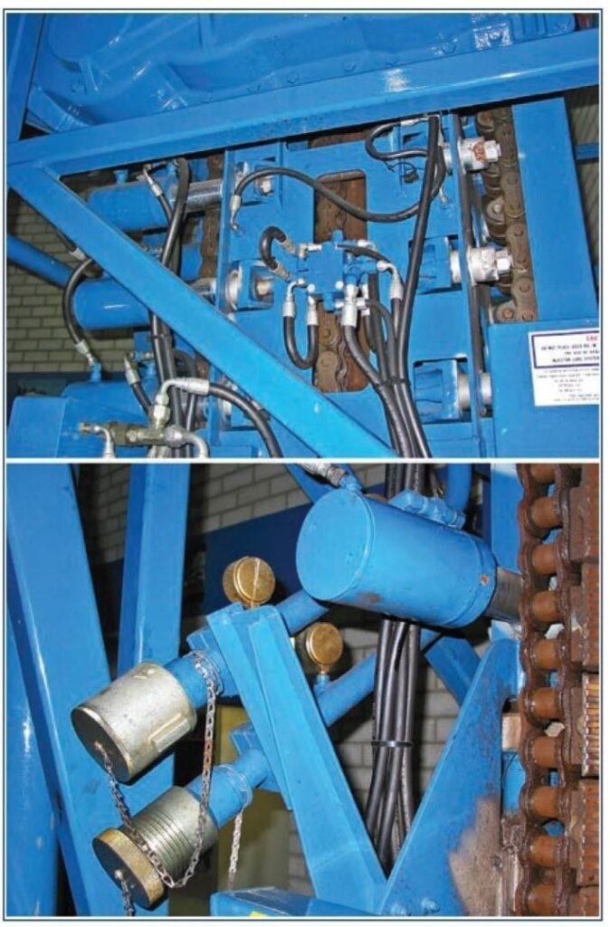
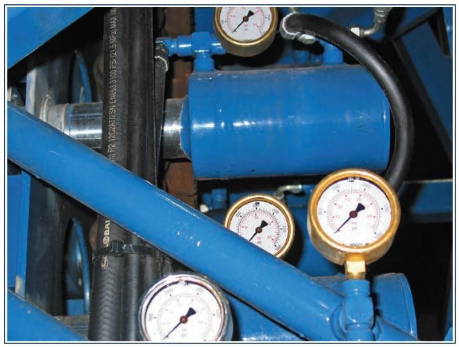
The injectors’ pulling capacity is dependent on how much hydraulic pressure is applied to the system, and which gear the system is in (high or low). The hydraulic pressures are variable and set by the Unit Operator. For example, one type of chain has a pulling capacity of 14,970 kg (33,000 lbs) when 207 bar / 20,700 kPa (3000 psi) hydraulic pressure is applied. In addition, the hydraulic drive motors have brakes that will hold the tubing should the hydraulics fail.
Subframe Of the Coiled Tubing Injector Head
The complete assembly is mounted in a subframe, one side of which is hinged and the other rests on a load cell. The forces exerted by the action of the drive system and the tubing weight are applied along the centerline of the tubing and cause the subframe to pivot. The compression of the load cell registers the weight of coiled tubing and Bottom Hole Assembly via a weight indicator on the control panel.
Compression on the load cell due to increased tubing load or overpull on the tubing by the injector will pressurize the fluid within it and this will be felt by the control cabin by a positive deflection of the needle on the weight indicator. The reverse is when the tubing is compressed downhole due to hole friction or downhole obstruction. This will lighten the coiled tubing and thus give a negative deflection on the weight indicator.
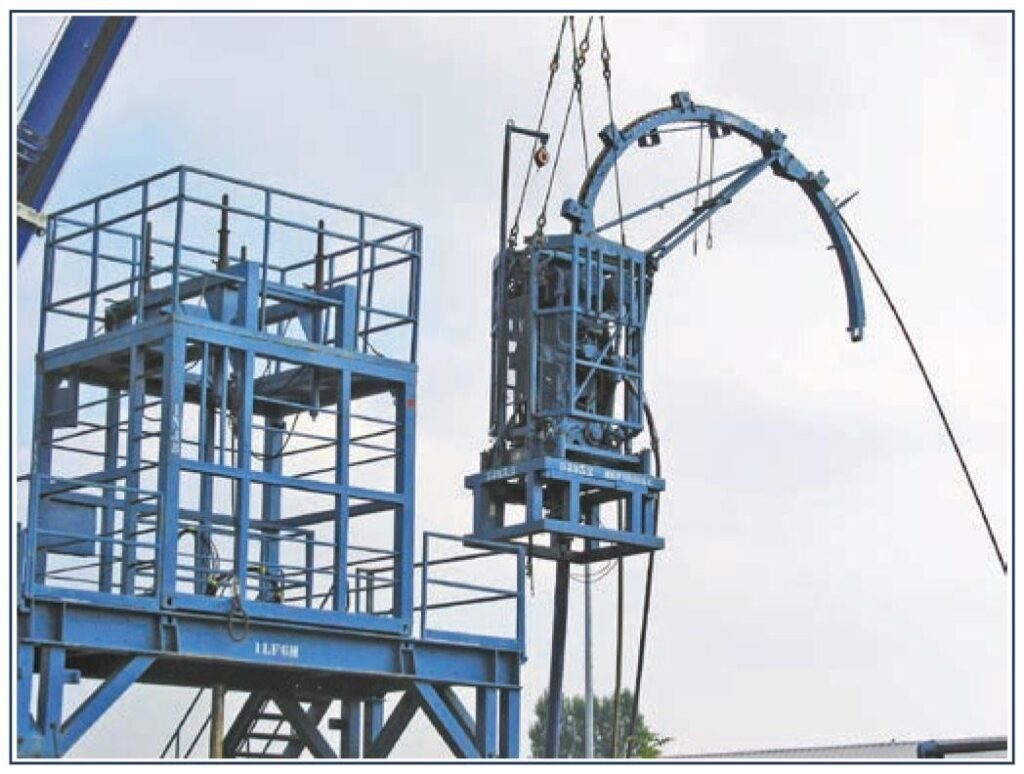
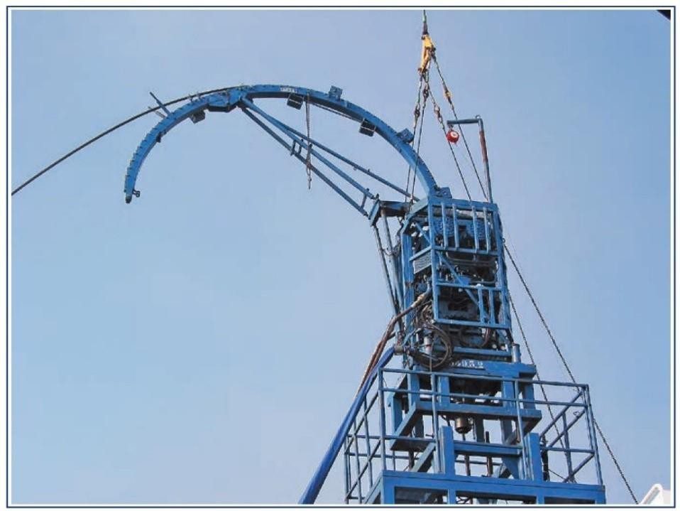
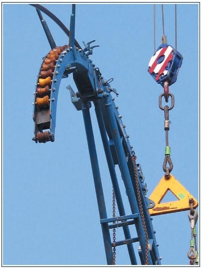
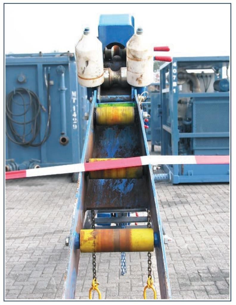
Roller Guide & Gooseneck
To complete the injector equipment there is a roller guide and gooseneck located on top of the mainframe. This supports the tubing during its transition from motion along the vertical axis of the wellhead to the horizontal axis of the storage reel, ensuring that the tubing is not excessively bent between the injector and the reel unit. They come in different radii, which coincides with the core radius of the reel drum. These range in sizes from 1372 mm to 2490mm (54″ to 98″) depending on the diameter of the tubing. The gooseneck itself must then be secured properly to prevent the guide from shifting around during the operation.
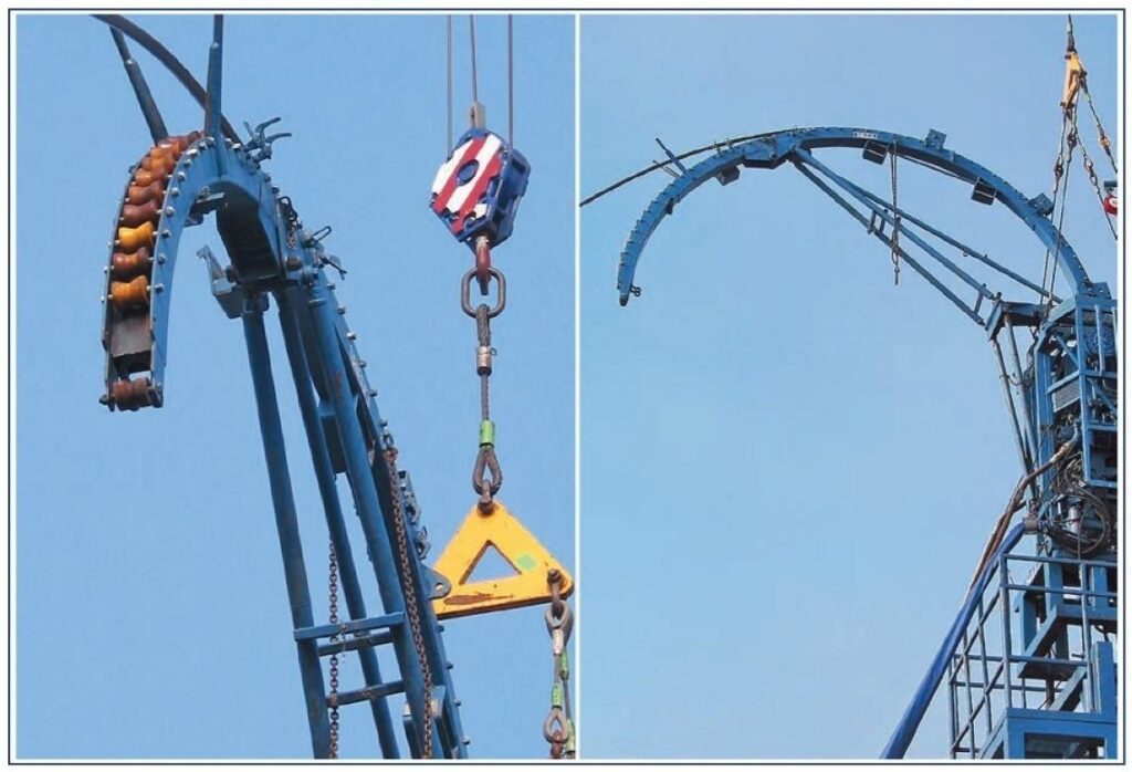
During rig-up it is vital that the gooseneck is properly installed onto the injector head to maintain an arc for the coiled tubing. Failure to do this may result in erroneous weight indicator readings when running in a hole.
Final Words
Typical injectors are capable of exerting a maximum upward pull or downward thrust on the tubing of 18,150 kg to 27,215 kg (40,000 lb to 60,000 lb). Larger units are also available for use with the larger sizes of coiled tubing.
| Weight of Injector Head with Gooseneck | 3540 kg (7800 lbs) |
| Speed (maximum with engine @ 2000rpm and 340 l/min or 90 gpm being pumped) | Low gear = 35m/min (115 ft/min), High gear = 70m/min (230 ft/min) |
| Pull (maximum with engine @ 207 bar or 3000psi) | Low gear = 17,690 kg (39,000lbs), High gear = 9,980 kg (22,000lbs) |