Drill collar vs drill pipe: the key differences are construction and function. Drill pipe forms the long connection between the surface equipment and the bottom hole assembly (BHA). Drill collars concentrate weight and stiffness within the BHA. However, both components transmit torque, carry axial loads and provide an internal passage for drilling fluid. [1],[2]
This distinction matters when identifying equipment, planning a drillstring or interpreting weight on bit (WOB). A collar is not simply a stronger grade of drill pipe. Its geometry, connections and position give it a different mechanical function. [1],[2]
Also, the collar section is only part of the BHA. Stabilizers, downhole motors, jars, reamers and other tools can occupy the lower assembly. Consequently, “near the bit” describes the collar’s general location; it does not mean every collar connects directly to the bit. [2]
Drill Collar vs Drill Pipe: Quick Comparison
| Feature | Drill pipe | Drill collar |
|---|---|---|
| Main purpose | Connects the surface to the BHA and transmits loads, rotation and fluid | Adds concentrated weight and stiffness to the BHA |
| Typical position | Main string above the BHA | Within the BHA near the bit |
| Body | Relatively thin-walled tube | Thick-walled tubular body |
| Fluid passage | Central bore | Central bore; the finished collar is hollow |
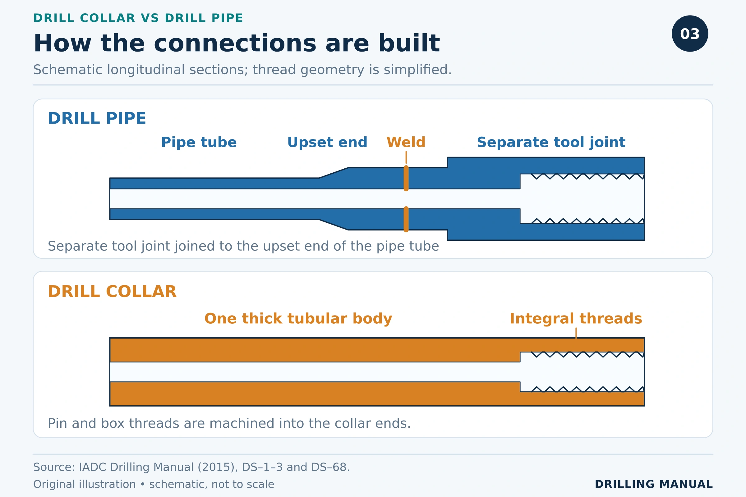
| Connections | Separate tool joints usually welded to conventional steel pipe | Pin and box machined into the collar ends |
| Bending response | Usually more flexible | Usually stiffer |
| Conventional vertical loading | Design generally aims to keep ordinary pipe in effective tension | Lower collars can carry compression; upper collars may remain in tension |
| Important checks | Tension, torque, fatigue, wear and connections | WOB, buoyancy, buckling, sticking and connections |
These are typical comparisons, not product ratings. Actual performance depends on dimensions, material, condition and the complete assembly. [1],[2]
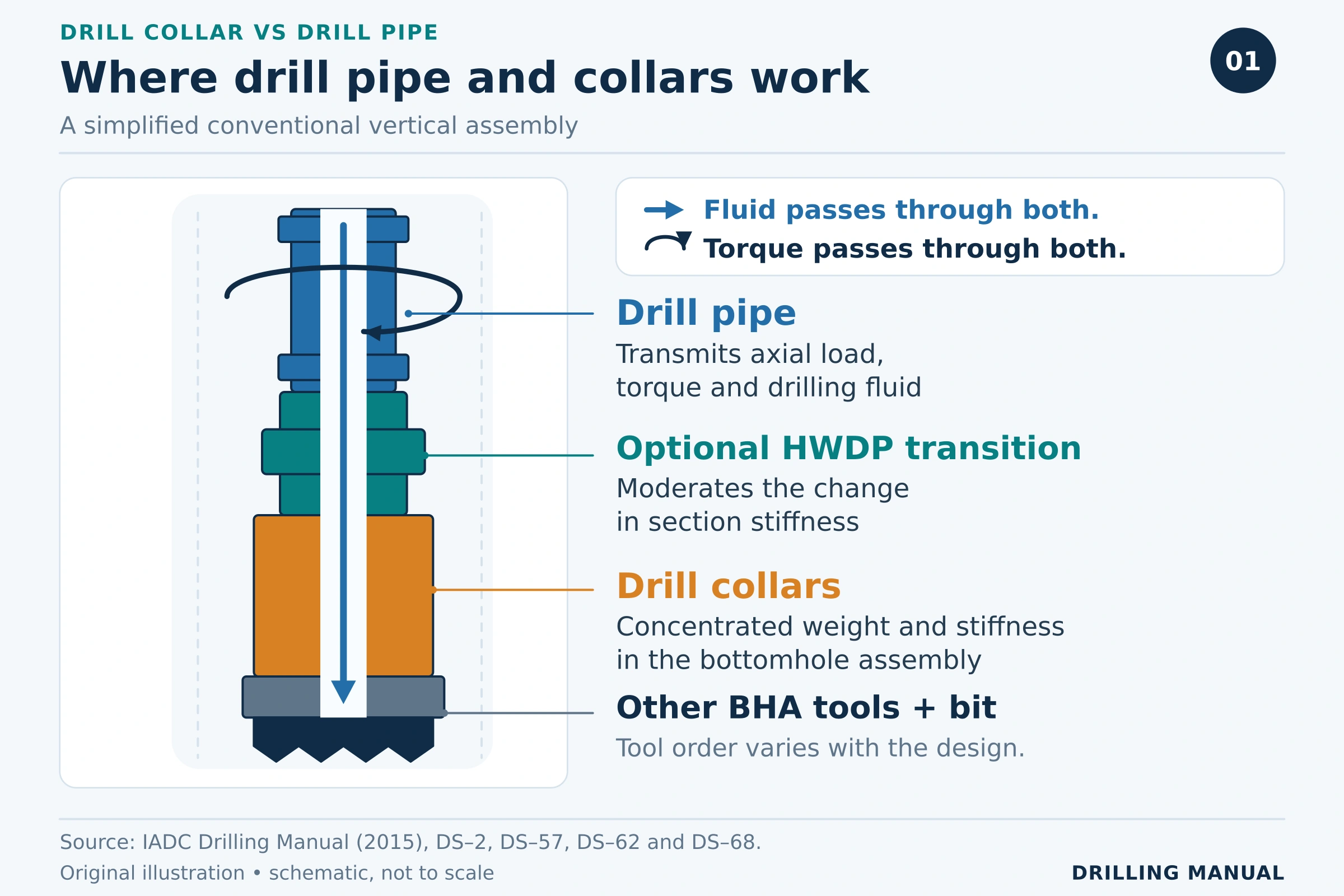
See the BHA components guide for the wider assembly context.
Construction: Body, Bore and Connections
Drill pipe construction
Conventional steel drill pipe uses a tubular body with thickened, or upset, ends. Manufacturers usually attach separate tool joints by friction or inertia welding. These enlarged connection sections differ visibly from the slimmer pipe body. [1]
The body and connections must work together. Therefore, a pipe-body rating alone does not establish the capacity of the complete joint. Connection geometry, remaining dimensions and wear also matter. [1]
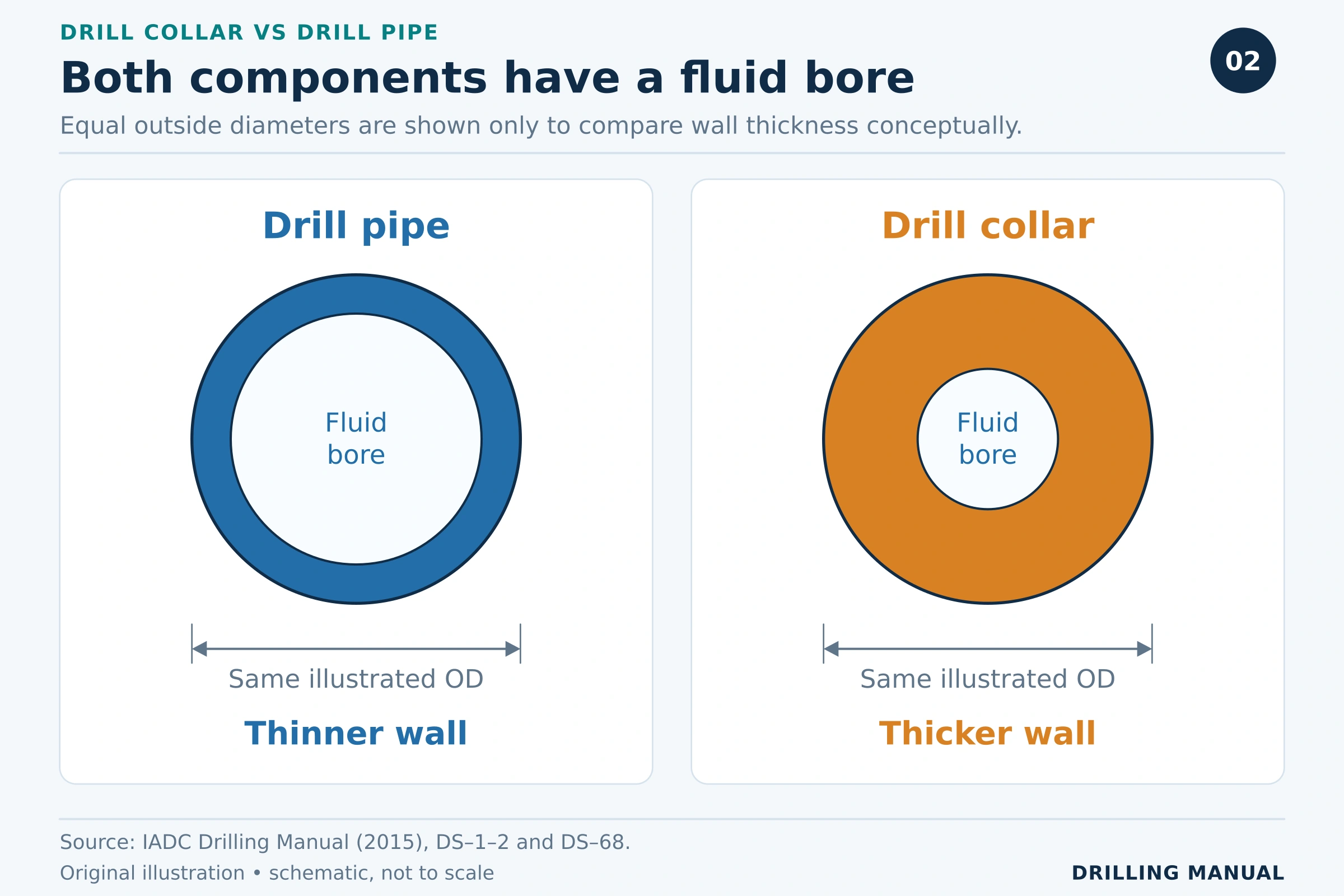
During conventional circulation, fluid travels down the internal drillstring passage, through the bit and back up the annulus. It therefore passes through the collar bore as well as the pipe bore. Their different wall thicknesses do not make either component’s fluid passage optional. [2]
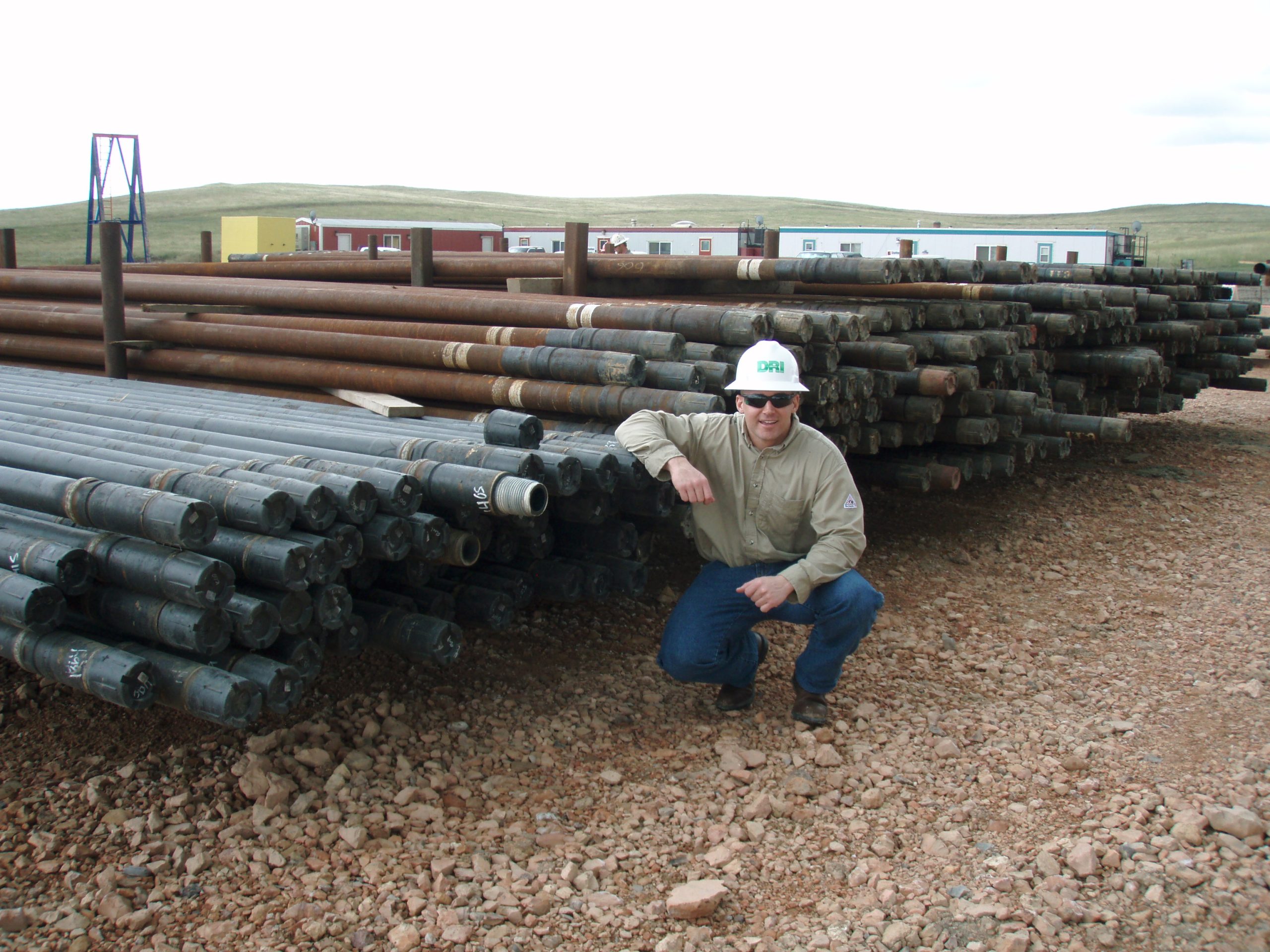
Photo: Joshua Doubek (2011), Drill Pipe, via Wikimedia Commons. CC BY-SA 3.0. Resized by WordPress; no other edits.

Drill collar construction
A conventional drill collar has a much thicker wall and a central bore. Although manufacturers may start with solid bar stock, they machine a passage through it. Calling a finished drill collar a solid rod is therefore misleading. [1]
The pin and box are machined into the collar ends. Collars may also have handling recesses or other features, depending on the design. Consequently, crews must identify the actual component and its handling provisions rather than rely on appearance alone. [1]
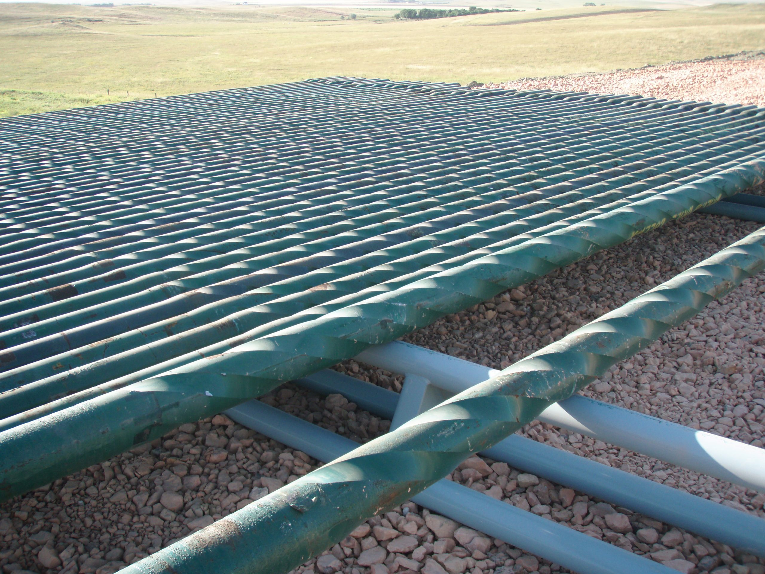
Photo: Joshua Doubek (2011), 6.5 in drillar collar, via Wikimedia Commons. CC BY-SA 3.0. Resized by WordPress; no other edits.

Why connections deserve a separate comparison
In drill collar vs drill pipe comparisons, similar-looking threaded ends can hide different construction. The pipe has a separate tool-joint section; the collar connection is integral to its body. Correct identification matters when checking inspection requirements, compatible connections and make-up torque. [1]
Weight and Stiffness: Related, but Different
The larger metal section of a typical collar increases its weight per unit length and its resistance to bending. Nevertheless, weight and stiffness describe different properties. Weight depends on the amount and density of material; elastic bending stiffness depends on material modulus and cross-sectional geometry. [1],[2]
This explains why a higher-strength pipe grade does not automatically provide the same bending stiffness as a collar. Likewise, a heavier component is not automatically the best choice through a curved interval. The assembly must suit the trajectory and expected loading. [1],[2]
For detailed dimensions, use the drill collar specifications guide alongside the actual equipment records.
Drill Collar vs Drill Pipe Under Load
In a simplified vertical well, the lower assembly transfers part of its supported weight to the bit. A common design objective is to keep ordinary drill pipe in effective axial tension while the lower BHA carries compression. [1],[2]
However, this does not mean every collar is compressed. The effective neutral point can lie within the collar section: collars above it remain in tension, while those below it carry compression. Here, “effective” accounts for pressure effects; it should not be confused with true axial force in the steel wall. [2]
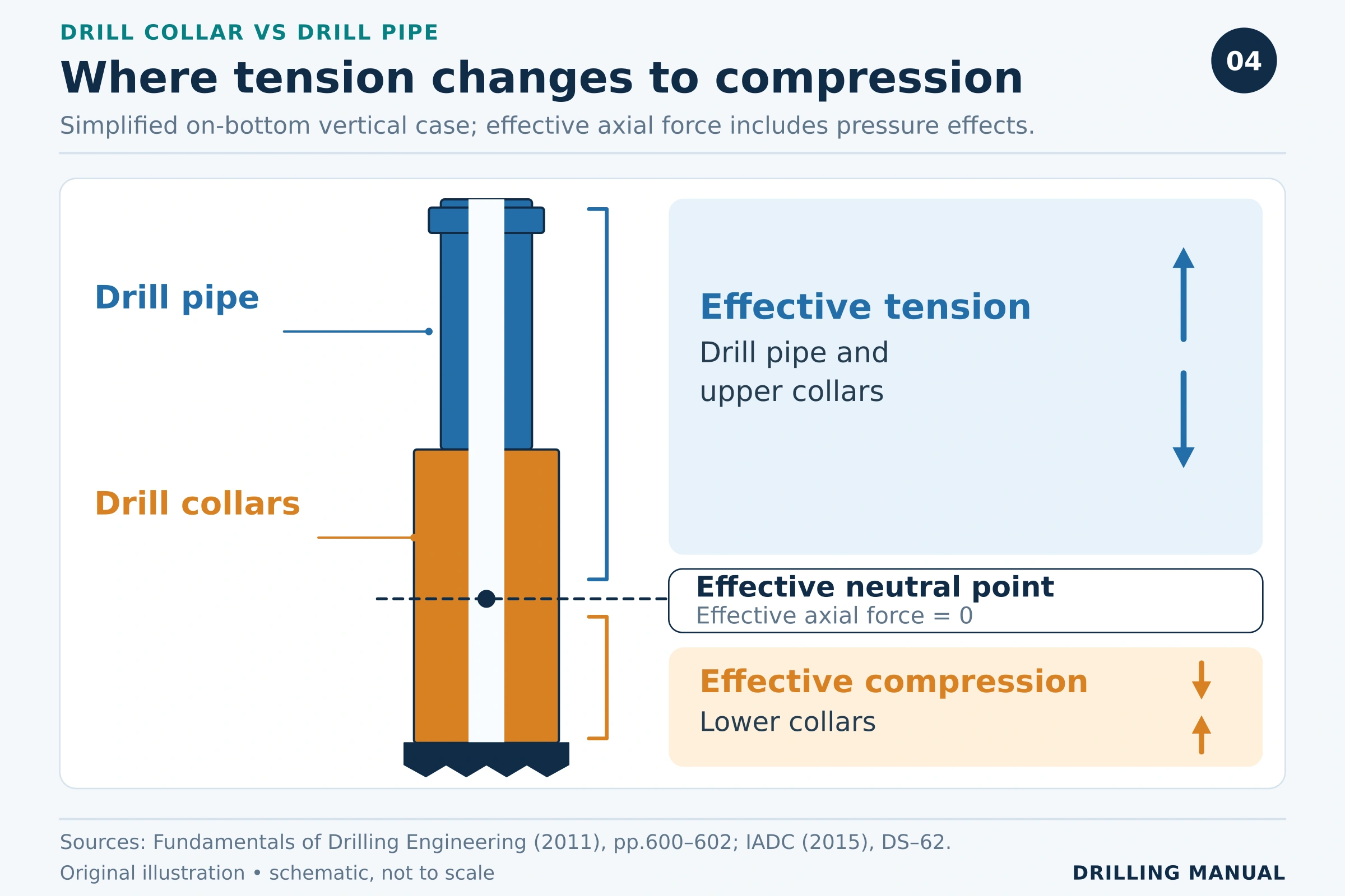
Highly inclined and horizontal wells require a different assessment. Gravity acts differently along the well path, while wall contact and drag affect force transfer. Therefore, the familiar vertical tension/compression sketch should not become a universal rule for directional drilling. [1],[2]
Surface hookload changes also need interpretation. In a horizontal well, setting down a particular surface load does not necessarily apply the same force at the bit. Downhole weight measurements can help assess the actual loading. [1]
Worked example: buoyed collar weight
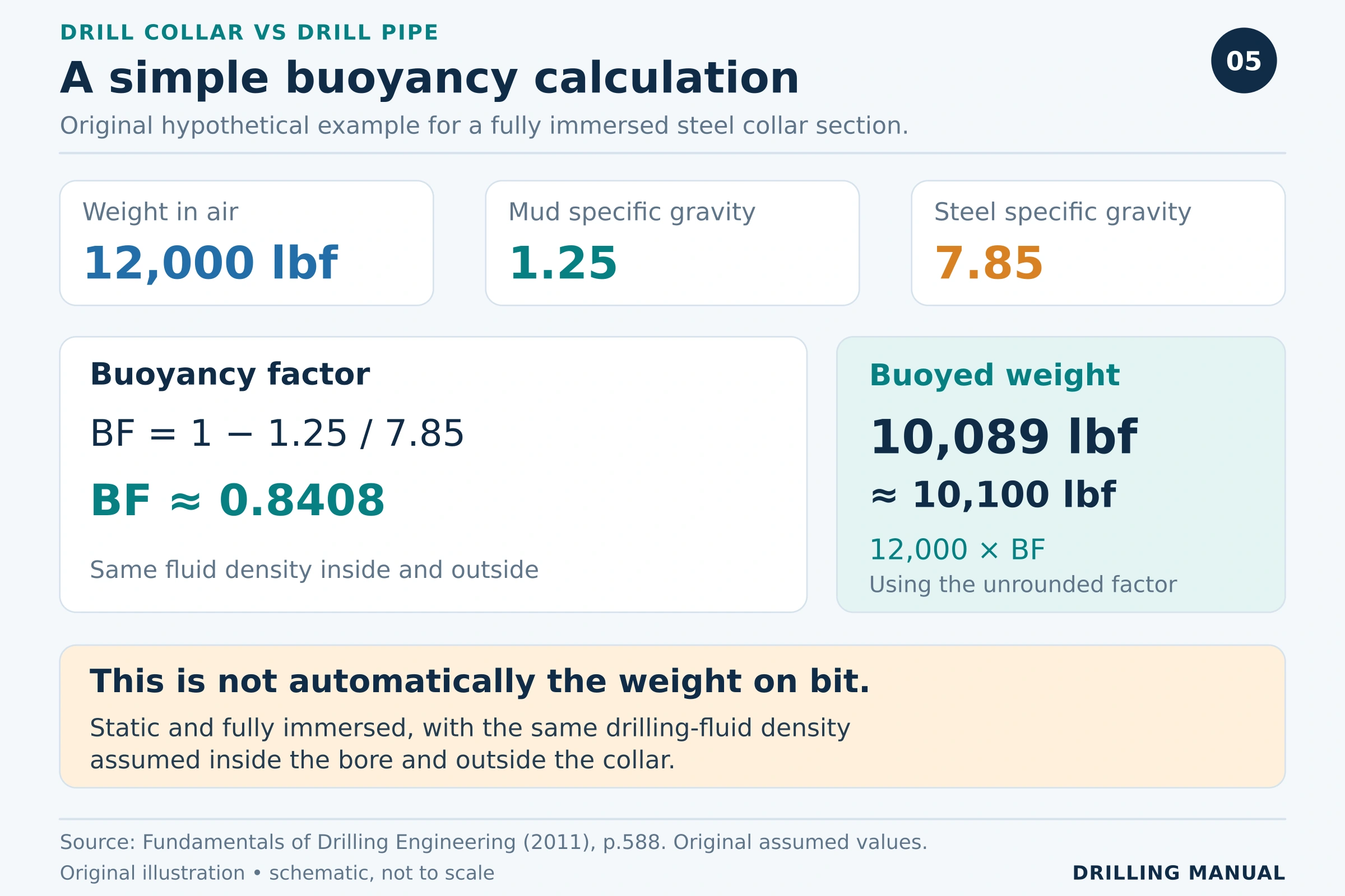
Consider a hypothetical collar section weighing 12,000 lbf in air. Assume static, complete immersion, the same fluid density inside and outside, mud specific gravity of 1.25, and steel specific gravity of 7.85. [2]
Buoyancy factor = 1 − 1.25 / 7.85 = 0.8408
Buoyed weight = 12,000 × 0.8408 ≈ 10,100 lbf
This original calculation illustrates a reduction in supported weight. It does not specify an operating WOB. The required tension margin, inclination, drag and complete BHA design still need consideration. Consequently, neither 12,000 lbf nor 10,100 lbf should be treated automatically as the force delivered to the bit. [1],[2]
Where Heavyweight Drill Pipe Fits
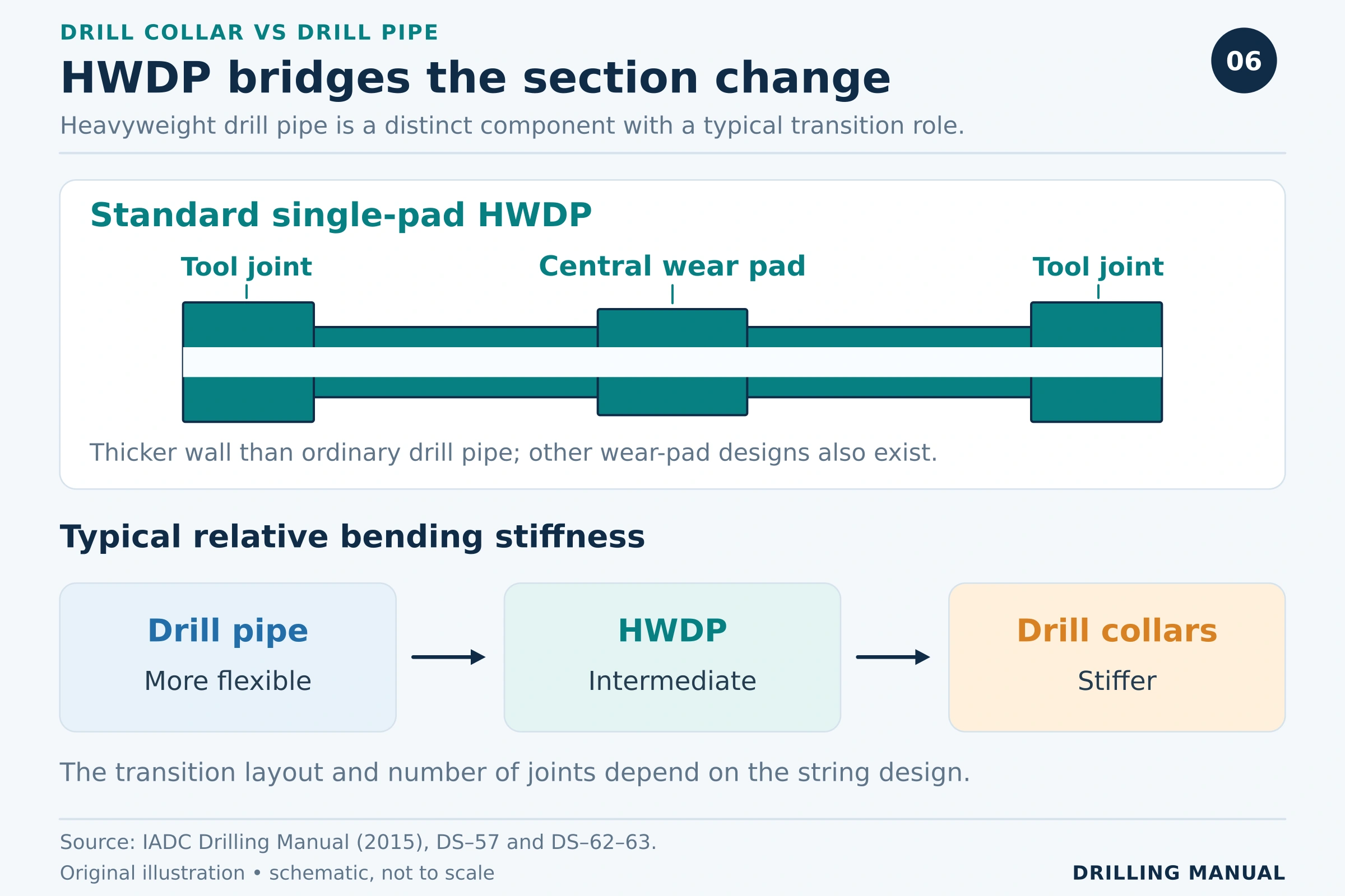
Heavyweight drill pipe (HWDP) is a separate component class. It resembles drill pipe but has a thicker wall and wear-pad features. A standard configuration includes a central wear section, although other arrangements exist. [1]
HWDP can provide a transition between relatively flexible pipe and stiff collars. This helps moderate an abrupt change in bending response. In some directional assemblies, it also contributes weight or carries compression where a long, stiff collar section would be unsuitable. [1]
Accordingly, a drill collar vs drill pipe comparison should acknowledge HWDP without treating it as another name for either component. The required arrangement depends on the well; there is no universal number of transition joints. [1],[2]
Applications and Factors Affecting Selection
Ordinary drill pipe provides the main working connection to the BHA. Collars provide concentrated lower-string weight and stiffness where the design requires them. Spiral collars can reduce the tendency for differential sticking, while nonmagnetic collars help limit interference with magnetic directional instruments. These features address different needs. [1],[2]
Before selecting components, consider:
- Trajectory and doglegs: curvature affects bending, contact and fatigue exposure.
- Required WOB and mud density: buoyancy changes supported weight; trajectory and drag affect its transfer.
- Outside diameter and bore: geometry affects stiffness, clearance and the hydraulic passage.
- Grade, connections and condition: body strength alone cannot describe the assembly’s capacity.
- Handling arrangements: use compatible equipment and the requirements for the actual product. [1],[2]
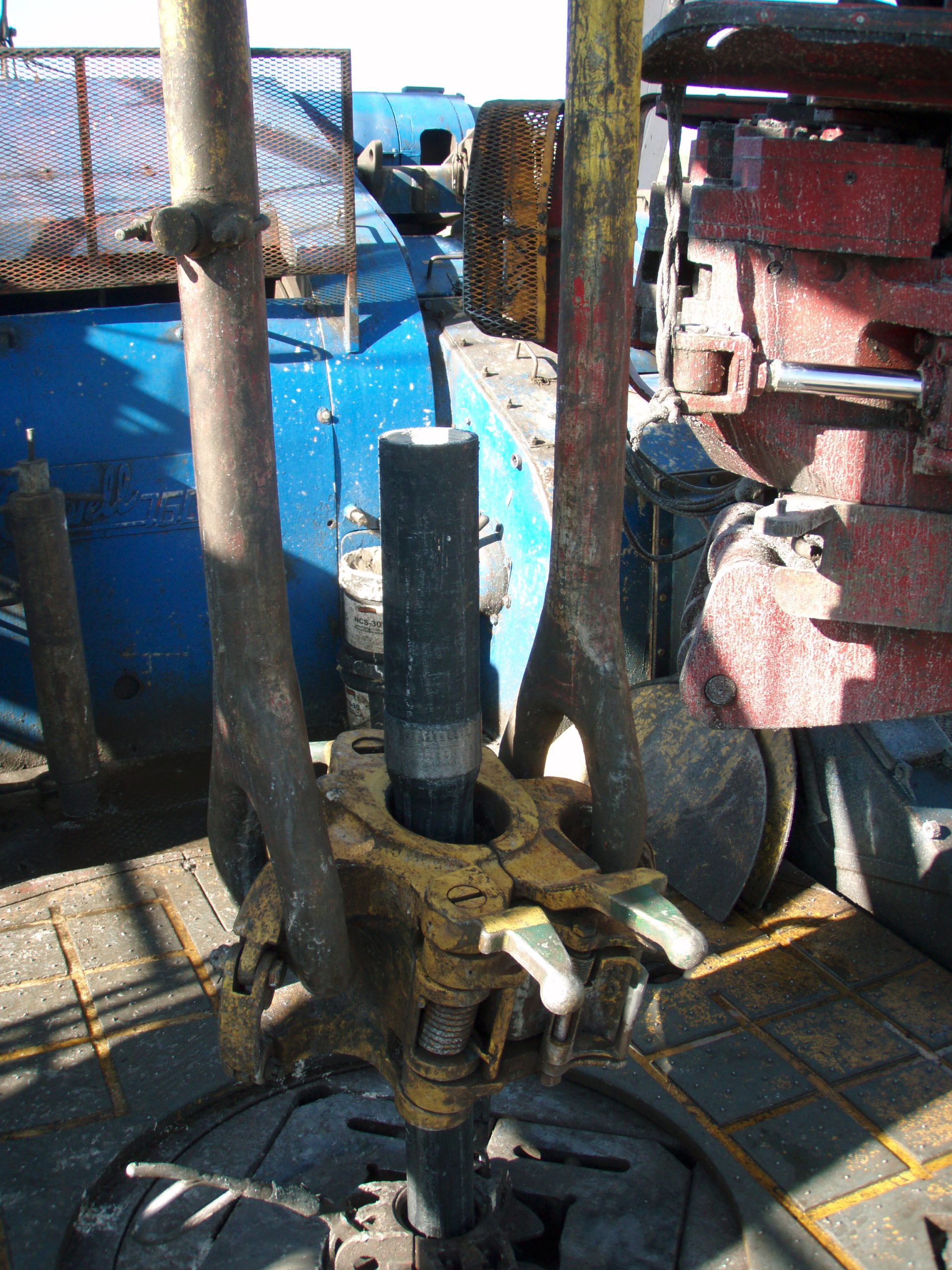
Photo: Joshua Doubek (2011), A joint being pulled out from the Rotary Table, via Wikimedia Commons. CC BY-SA 3.0. Resized by WordPress; no other edits.

These checks belong together. For example, increasing collar dimensions may add weight and stiffness, but it also changes clearance and bending behaviour. Selection should therefore address the whole BHA instead of maximizing one property. [1],[2]
The hydraulic program is another selection input. Fluid properties, planned flow rate and bit nozzles form part of the collar-sizing assessment. Similarly, an acceptable assembly must fit the hole and planned casing program while meeting the permitted dogleg requirements. A weight-only comparison misses these constraints. [2]
Limitations and Practical Rules of Thumb
Collars are not immune to buckling. Similarly, keeping drill pipe in axial tension does not eliminate fatigue: rotation through a dogleg can still produce repeated bending. Spiral grooves reduce a sticking tendency; they do not guarantee a stuck-pipe-free operation. [1],[2]
Use these qualitative rules when reviewing drill collar vs drill pipe:
- Separate three weights: air weight, buoyed weight and delivered WOB are different quantities.
- Identify the complete load path: assess the body, connections and transitions together.
- State the well geometry: a vertical-well explanation may not apply to a horizontal section.
- Check actual equipment data: use connection-specific torque and handling requirements instead of generic values. [1],[2]
These rules support an engineering review; they do not replace a well-specific load assessment.
Frequently Asked Questions
Can drill pipe replace drill collars?
They are not automatically interchangeable. Ordinary pipe does not reproduce a collar’s concentrated weight and stiffness. Some directional designs redistribute weight using HWDP, but that requires an assessment of the complete assembly and load transfer. [1]
How many drill collars are required?
There is no fixed count. Required WOB, collar unit weight, mud density, inclination and the chosen design margin affect the answer. Connections, bending and the other BHA components also constrain the final arrangement. [1],[2]
Which is stronger: drill collar or drill pipe?
“Stronger” needs a defined load case. A typical collar is stiffer and heavier per unit length, but tensile capacity, torsional capacity and fatigue resistance depend on geometry, material, connections and condition. Compare the relevant ratings rather than the component names. [1],[2]
Book References
[1] IADC Drilling Manual, 12th edition, first printing, March 2015. Drillstring chapter: DS–1–4, DS–7–8, DS–57, DS–62–63 and DS–68–70 (PDF pages 279–282, 285–286, 335, 340–341 and 346–348). User-uploaded copy: 730649080-IADC-Manual.pdf.
[2] Fundamentals of Drilling Engineering, edited by Robert F. Mitchell and Stefan Z. Miska, SPE Textbook Series, Volume 12, 2011. Chapter 9: printed pages 585–590, 596 and 600–602 (PDF pages 599–604, 610 and 614–616). User-uploaded copy: Fundamentals Of Drilling Engineering.pdf.
The technical explanations are paraphrased from these books. The numerical example and six diagrams are original teaching material. Photographs have separate creator and licence credits.