To select the proper drill collar for the bottom hole assembly, we should understand what is the drill collar specifications. Generally, drill collars are identified by the following parameters:
- Size (OD)
- ID
- Nominal WT
- Connection (Thread)
- Length
Drill Collar Sizes
The hole size and bit program will determine the best drill collar size, but the collars selected usually have the largest OD and maximum permissible wall thickness that can be safely run in the hole.
Several benefits will be derived from this general rule, namely:
- Fewer drill collars are needed for the required weight.
- Fewer drill collar connections are required.
- Less time is lost handling drill collars during trips.
- Factors governing good drilling bit performance favor close-fitting stiff members.
- Fatigue damage of connections is less with drill collars that fit the hole closely.
The buoyed weight of the collar string should be at least 15-20% greater than the maximum anticipated bit weight. The neutral point between tension and compression should always be kept within drill collar string. Tapered drill collar strings (two or more different sizes of drill collars) are often used in large-diameter holes to maintain stiffness change. The drill collar bore, primarily a hydraulic consideration, is determined by the minimum size to handle required circulation without excessive pressure drop.
Drill Collar Weight Specifications
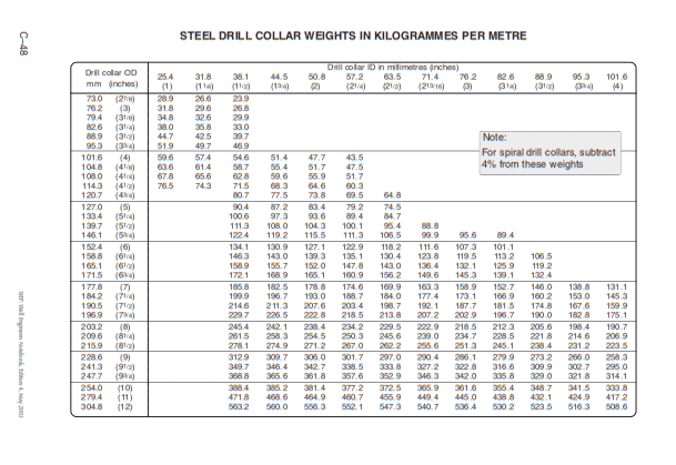
D/Cs are produced in an extensive range of sizes with various types of joint connections. The Drill collar size and weights per foot of a range of DC sizes are shown in Table 1 & 2. The weights quoted in these tables are the “weight in the air”. It is vital that proper care is taken when handling D/Cs. The shoulders and threads must be lubricated with the correct lubricant (containing 40- 60% powdered metallic zinc or lead).
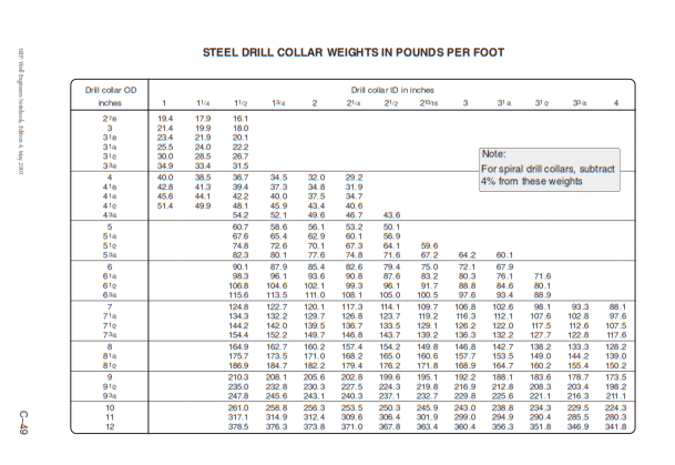
Calculations
As drill collars are uniform tubes of steel with few upsets (changes in ID or OD) across their length, it is easy to calculate their weight. We can calculate the weight of drill collars in kg/m or lbs/ft using the following formula:
SI units: 6.16 x 10⁻³ x (D2 – d2)
Field units: 2.67 x (D2 – d2)
Where :
- D = Outside diameter in mm/inches
- d = Inside diameter in mm/inches.
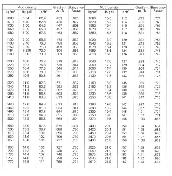
The table 3 below will help you with the weight calculations in the drilling fluid after considering the buoyancy factor.
Drill Collar Length Specifications
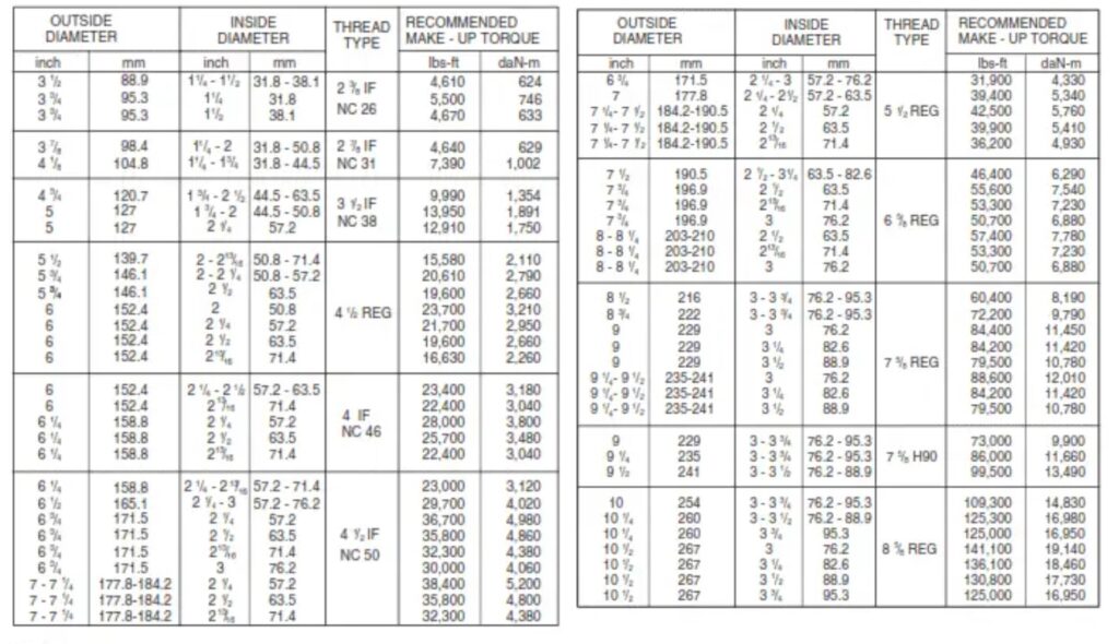
Drill Collar Connection & Thread Types
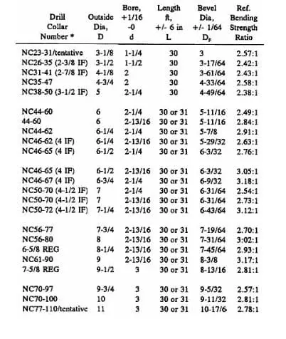
- The drill collar number (column 1) comprises two parts separated by a hyphen.
- The first part is the connection number in the NC style.
- The second part, consisting of 2 (or 3) digits, indicates their outside diameter in units and tenths of inches.
- The connections shown in parentheses in column 1 are not a part of the collar number; they indicate the inter-changeability of collars made with the standard (NC) connections, as shown.
- If the connections shown in parentheses in column 1 are made with the V-0.038R thread, the connections and drill collars are identical to those in the NC style.
- The drill collar sizes listed in Table 4 were adopted to provide a full range of drill collars with improved connections as a replacement for the drill collars with the various connections specified in previous editions of API specification.
Regular Connections
For some reason, Regular connections remain the most common choice for BHA components even though an NC connection of the same bending strength is superior due to its thread having a less sharp root radius and being more resilient to thread root cracking.
H90 Connections
These connections were originally a proprietary product of Hughes Tool Company and are easily recognizable by their shallow 90° thread angle. They are about equivalent performance to Regular connections except that the shallow thread angle causes high box hoop stresses at high makeup torques. Again, NC is a superior thread in almost all applications, but the H-90 type is still frequently used.
Notes
- The shoulder provides the only positive seal against fluid leakage.
- D/Cs with 8-1/4 and 9-1/2 inches outside diameters are shown with 6-5/8 and 7-5/8 REG connections since no NC connections are in the recommended bending strength ratio range.
- The connection is the weakest part of the entire BHA type.
- Improper M/U torque, improper or insufficient lubricant, and galling can all lead to connection failure.
- Purchase orders for collars with improved connections should state the D/C number or size and style, bore, and length. Purchase orders for collars with optional connections should state the outside diameter, bore, length, connection size and style, and bevel diameter.
- The DC connections go through tension-compression cycles and are subject to bending stresses.
The Make Up Torque
If the drill collar connection is suitable, and we apply the correct make-up torque, the joint should absorb the bending stresses encountered. In addition, the shoulder-to-shoulder seal will effectively contain the internal pressures.
Drill collar connections are never referred to as tool joints, although thread profiles may be the same as drill pipe tool joints. The OD and ID are different, so the pin and box areas are more significant, and therefore, the required make-up torque is more incredible.
The make up torque is the biggest single factor affecting the life and performance of drill collars. Improper torque will cause rapid fatigue damage and premature failure of the drill collar connections. If make-up torque is less than, say, 90% of the recommended value, the tool joint may not develop enough strength to:
- prevent wobbling
- resist bending loads
- form an adequate seal
- resist excessive makeup due to impact torque while drilling.
On the other hand, over-torquing is likely to distort and weaken the threaded connection, stretch the pin, or expand the box. Correct make-up torque is essential for trouble-free performance, and we should always measure the applied torque conscientiously.
Note: As collar make-up torques are high it is especially important to be careful when making up or breaking out connections. Should a tong slip or a tong line break the rig personnel not directly involved could be hurt, so make sure they remain outside the danger area.