Drilling slips are wedge-shaped segments with special dies inserted inside, which support the pipe when suspended in the rotary bushings. Figure 1 shows drill pipe and tubing slips with three body segments, while slips for drill collars and casing (Figure 2) are made up of many segments.
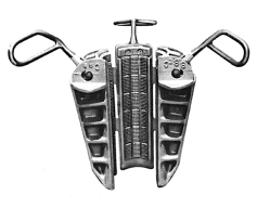
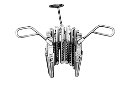
Figure 2: Casing slips
Design
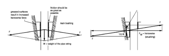
The slips in the master bushing use a wedging action to convert the weight of the drill string into a much greater lateral or transverse force on the pipe. This is illustrated in Figure 3. Without considering friction, you can think of it like a load suspended from a spreader bar that hangs on two slings at an angle equal to the angle of the rotary slips (a). The compression force in the spreader bar is equal to P/(2 tan a).
The slips must provide full circumferential grip for even load distribution due to the heavy weight of long casing strings and the relatively thin pipe wall.
The slip angle commonly used is 9°27’45”. Ignoring the effects of friction, if a string weight of 445 kN (100,000 lbs) is applied, it would result in a compression load of 1,334 kN (300,000 lbs) on the pipe in the slips. This is equivalent to a collapse pressure of 29,552 kPa (4,286 psi) on a 127.0 mm x 29.02 kg/m (5″ x 19.5 lb/ft) drill pipe, with 35.6 cm (14″) long slips that have a full circumferential grip over the entire length. The E pipe has a rated collapse pressure of 68,950 kPa (10,000 psi). You can refer to slip crushing article for more information on this topic.
Slips have concave replaceable inserts called dies, designed for specific sizes of pipe, to provide full circumferential gripping action.
Proper Drilling Slips Usage
Some important points have to be taken into account when handling slips:
- Please ensure that the slips, along with the inserts, are of the appropriate size for the pipe. Double-check the sizing to ensure a proper fit.
- Ensure that all the inserts are properly gripping the pipe.
- Please ensure that the inserts are sharp.
- Make sure that the taper of the slips matches that of the master bushings in the rotary table and is not damaged.
- Please ensure that the exterior of the slips are thoroughly cleaned and properly coated with grease.
- Make sure that the master bushing is securely fitted and does not have any looseness in the rotary.
- Please ensure that all slip handles are present and properly fastened.
Bad Practice
It is extremely bad practice to:
- Use the rotary slips to stop the downward movement of the drill pipe.
- Let the slips ride on the pipe while pulling out of the hole.
- Use the slips to catch the tool joint box.
Note: A spider is often used in the rotary instead of hand slips while running casing.
Drilling Pipe Slips
The right size slips must always be used for the size pipe being handled. Figure 4 shows the effects of using the wrong size of rotary slips on the drill pipe.
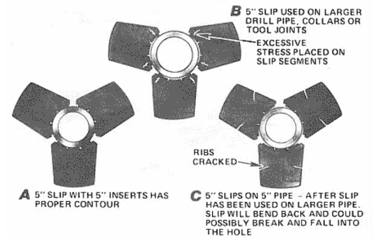
Drilling Slips with a smaller size than the pipe can damage the pipe, the corners of the slips, and even drop the pipe string. Conversely, slips that are too large will not make contact with the pipe all the way around, leading to the risk of dropping the pipe and destroying the central part of the slips gripping surface.
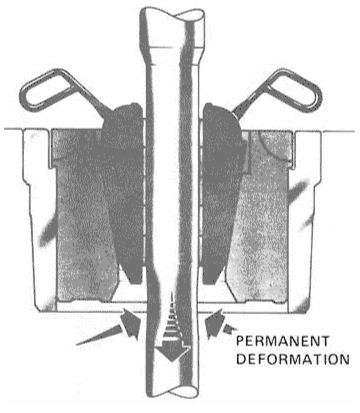
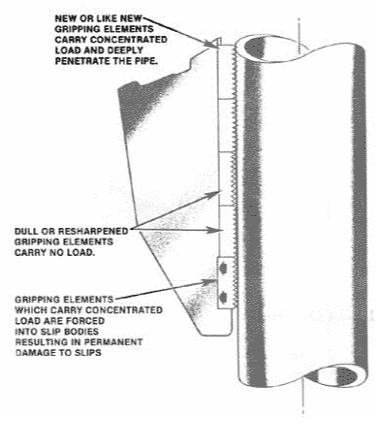
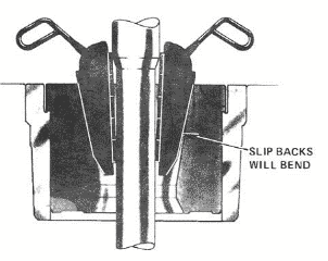
The drawworks brakes should be used to stop the downward motion of the drill pipe, not the slips. Figure 5 shows the effects of stopping the motion of the pipe with slips. This can occur if floor hands fail to set the slips at the appropriate time after the driller has stopped the pipe. Do not let the slips “ride” on the pipe while the pipe is being pulled out of the hole. This practice accelerates the wear on the gripping elements of the slip. It also risks having the slip ejected from the master bushing bowl when a tool joint comes through and causing possible injury to personnel. Inserts that are new or “like new” are designed to bear a concentrated load and penetrate deeply into the pipe. Resharpened inserts carry no load. Inserts that carry a concentrated load are forced into slip bodies, resulting in permanent damage to rotary slips.
Be careful not to catch the tool joint box in the slips when the driller slacks off. This often happens when coming out of the hole, and the driller does not pick up high enough for the slips to fall around the pipe properly. This can ruin the slips and damage the tool joint box and the pipe’s body.
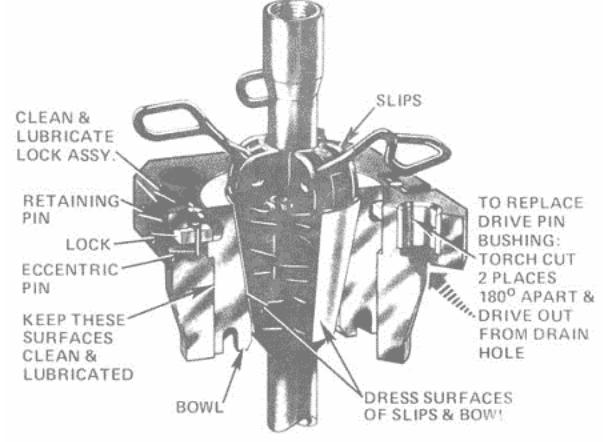
Routine care and Maintenance will extend the service life of the drill pipe slips, protect the drill pipe and reduce the danger of sticking slips. Figure E2-9 indicates points of maintenance and lubrication.
Inspection of Drill Pipe Slips
It is important to physically inspect the slips before every trip. If the inserts are not secure, remove the slips from service until they can be repaired. If cracks are detected in the slip bodies, they should be removed from service and destroyed to prevent future use.
Periodic Inspection
At least every three months, the slips should be more thoroughly checked. Place a straight edge on the backs and faces of the slips. If the slips are bent or worn, the straight edge will not make full surface contact with them. The backs of the rotary slips should be straight and smooth. If they are excessively worn, they should be replaced. Use a magnetic particle inspection or a similar method to detect fatigue cracking in the slip bodies, webs, and toes. If any cracks are detected, the slips should be removed from service and destroyed to prevent future use. Check the insert slots for damage or excessive wear. If there is 1/8″ to 3/16″ clearance between the back of the inserts and the insert slot, replace the slips. With worn insert slots, there is a risk of losing the inserts down the hole.
Lastly, slip tests should be conducted every three months to determine slip wear and/or master bushing wear.
Spare Parts
It is easy to find spare parts to fix recently manufactured slips. Typically, the inserts, dies, or liners are the parts that need to be replaced most frequently. It is important to never mix new inserts with worn or resharpened ones. Section B4 of the IADC drilling manual provides additional information about resharpened inserts. To ensure that the slips work properly, they must be kept clean and not mistreated. The hinge pins should be well lubricated and the backs should be fully coated with high-quality anti-seize compound before use.
Hints
- Drill Pipe slips can vary to accommodate pipe from 2.3/8″ to 7″ diameter. There should be a 4″/ ft taper on the diameter as per API design to permit operation on standard master bushings. They can be manual or powered.
- Drill pipe slips can be manufactured in short, medium, and long lengths.
- For deep well and heavy string applications, it is recommended to use long or extra-long slips.
- Powered slips eliminate the heavy lifting required by personnel, are much safer, and ensure consistent usage/operation, thus minimizing pipe wear and damage.
- Power slips can be mechanical, pneumatic, or hydraulic.
- Manual slips are more effective when designed to be simple and easily replaceable if they turn out to be defective.
Drill Collar Slips
Generally, the specifications for taper are the same as those listed for drill pipe slips. Before using the slips, check their general condition and size range to ensure they are suitable for the collars being run. Look for any signs of damage, such as cracks, missing cotter keys, loose liners, dull liner teeth, bent back tapers (which may occur due to catching on the drill collar shoulder), and bent handles.
Drill collar slips can range from 3″ to 14″. There should be a taper of 4″ / ft on the diameter as per API design. A full wrap-around design assures positive holding and slip setting. The top of the drill collar slips is flat to allow for the Safety Clamp (also known as the dog collar).
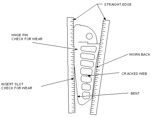
Inspection Procedure
- Verify and record BP Tool No. and/or unique identification No. stamped on the unit.
- Check for wear at the back, insert slot and hinge pin. A straight edge can be used to detect even wear and damage.
- Check for bending of the back edge.
- Check web with Magnetic Particle Inspection (NDT).