An electric submersible pump (ESP) is an artificial-lift system that adds energy to the produced fluid downhole. You may also see the name written as electrical submersible pump. A power cable feeds an electric motor, the motor turns a shaft, and a series of centrifugal stages raises the fluid pressure between the pump intake and discharge. In a conventional oil-well installation, the discharge feeds the production tubing. [1], [2]
Two wells can have pumps set at the same depth and need different numbers of stages. For example, one may deliver fluid to the intake at higher pressure, while the other faces more tubing friction or higher wellhead pressure. A useful ESP comparison therefore starts with two quantities together: the rate through the pump and the head it must develop at that rate. [1], [2]
How Does an Electric Submersible Pump Work?
First, follow the electricity. At surface, a transformer supplies the required voltage and a controller protects the motor. A cable secured along the tubing carries three-phase power downhole. From there, the shaft carries torque through the protector to the pump above. A variable-speed drive, where fitted, can change the motor speed by changing the supply frequency. [1], [2]
Next, trace the fluid path. In the arrangement shown, the producing interval is below the assembly. Well fluid travels upward past the motor before entering the intake. It then passes through the pump stages and into the tubing. This route does two jobs: it supplies liquid to the pump and carries heat away from the motor. [1], [2]
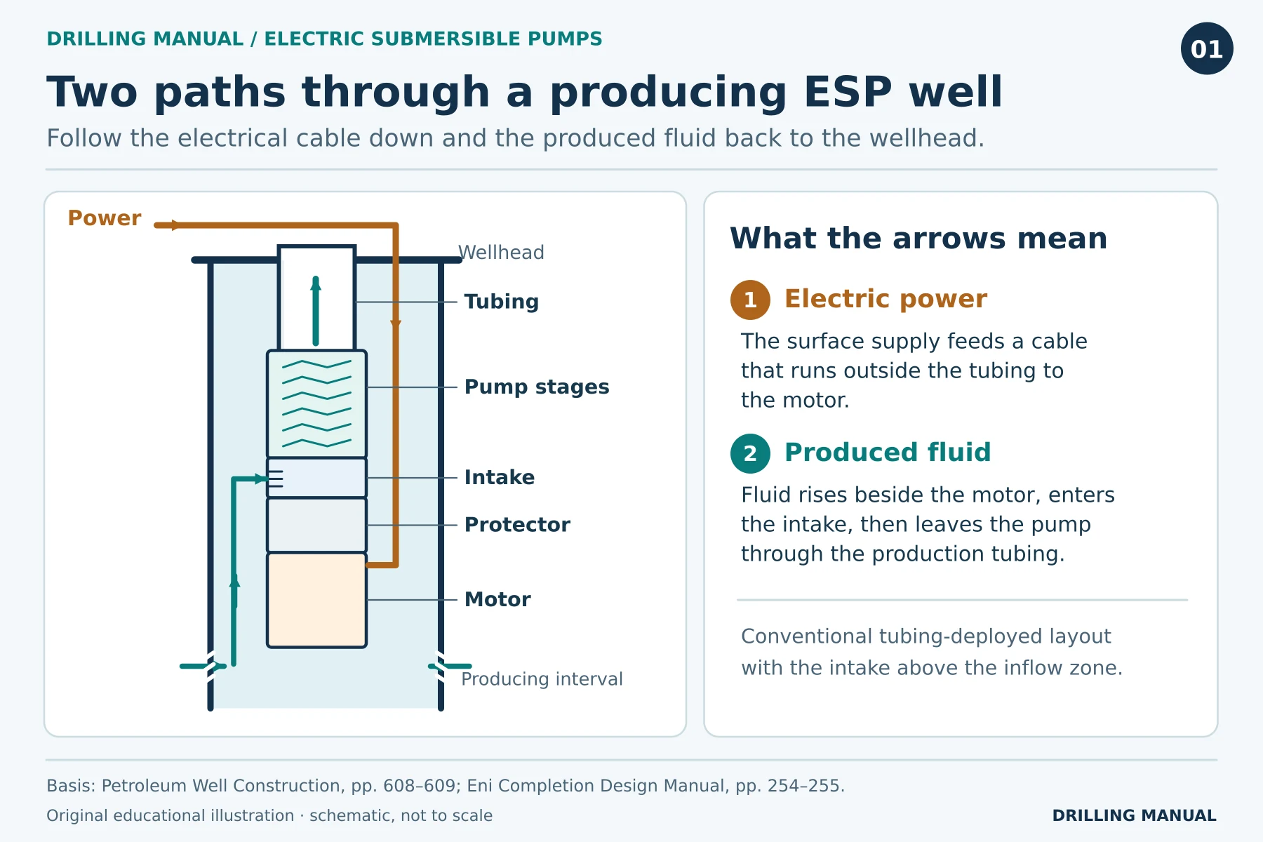
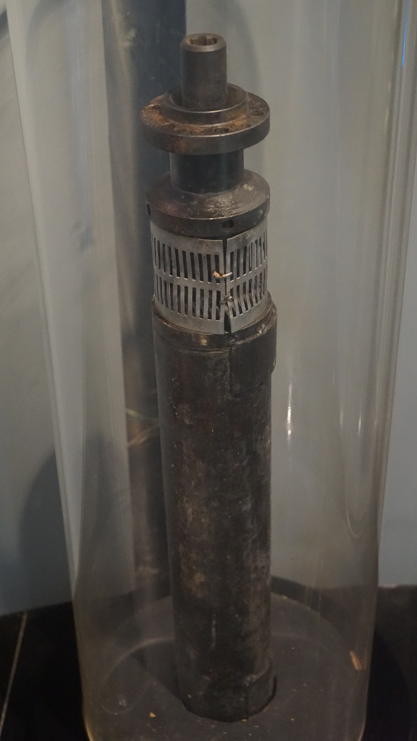
Photo: Huanokinhejo, Wikimedia Commons · CC BY-SA 4.0. Resized and re-encoded.

ESP Components: Which Part Does What?
| Component | Function in a conventional installation |
|---|---|
| Motor and power cable | The cable supplies electrical power; the motor converts it to rotation. |
| Protector or seal section | Transmits torque, carries shaft thrust and accommodates motor-oil expansion while keeping well fluid out of the motor. |
| Intake or gas-separating intake | Admits well fluid; a suitable separator can divert some free gas before fluid enters the pump. |
| Multistage pump | Rotating impellers add energy to the stream as it passes through successive impeller and diffuser stages. |
| Surface controls | Provide control and electrical protection. Depending on the installation, voltage, current and operating history are available for review. |
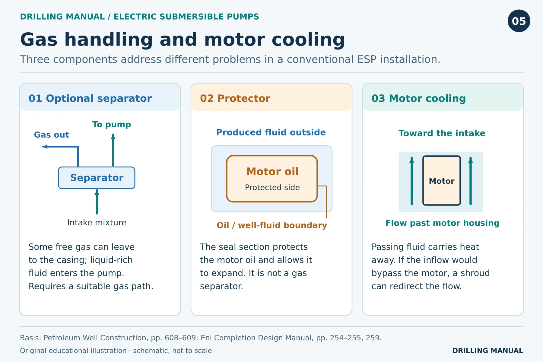
The protector and gas separator are easy to confuse on a simplified assembly drawing. The protector serves the motor, whereas the separator acts on the produced stream before it reaches the stages. That difference matters when you read a completion drawing: the two parts are not interchangeable. [1]
Why Does an ESP Have So Many Stages?
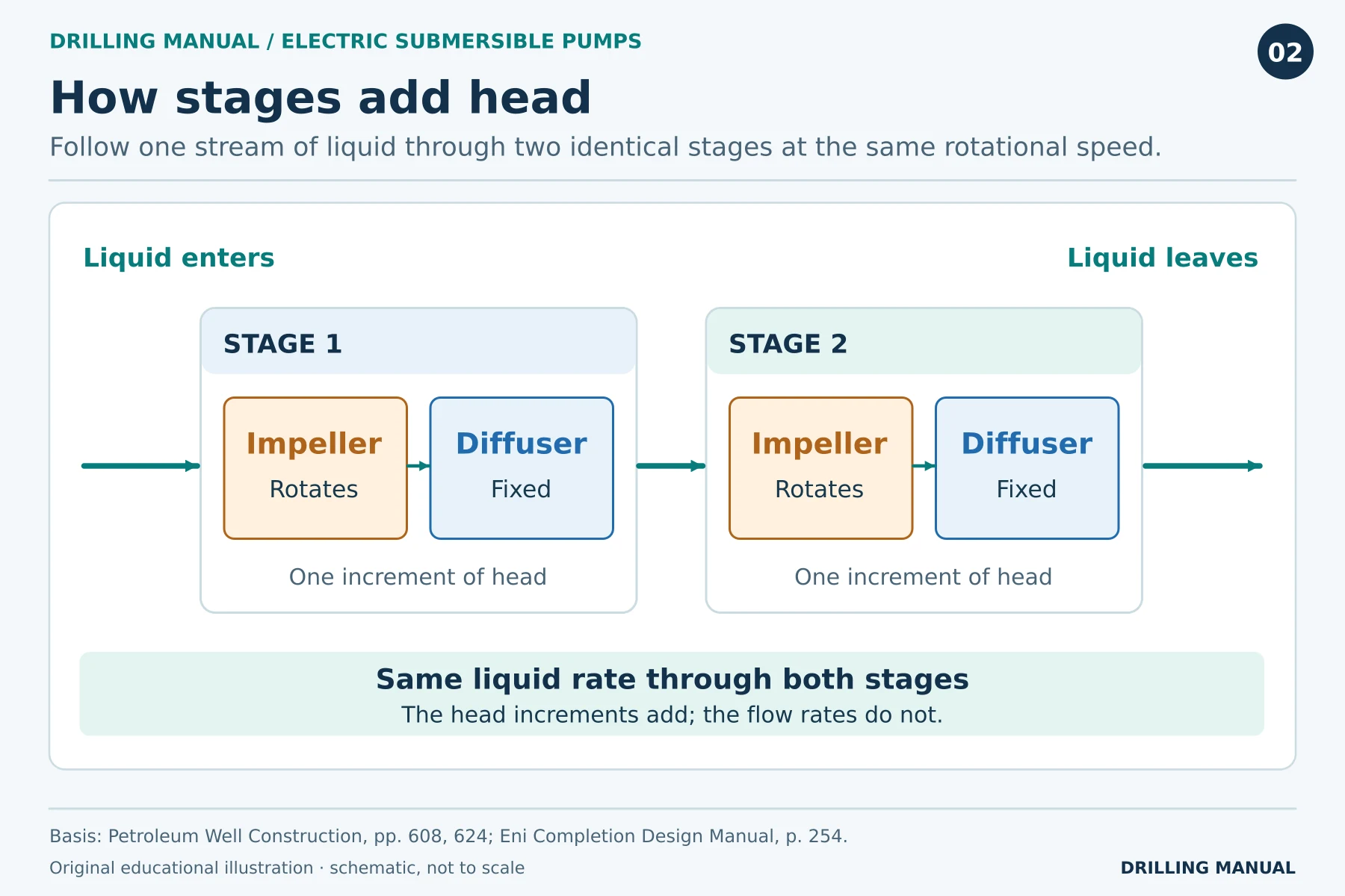
Each ESP stage has a rotating impeller and a stationary diffuser. The shaft turns the impeller, which accelerates the liquid. Some of that velocity energy becomes pressure as the stationary diffuser guides the stream toward the next impeller. Although the stages share a shaft, each one contributes only part of the total head. For a liquid treated as incompressible, the stages in series pass essentially the same volumetric rate, while their heads add. Thus, doubling the number of identical stages doubles their combined head at the same rate and speed. The well’s production rate, however, does not necessarily double. [1], [2], [5]
Head expresses the energy added per unit weight of liquid as an equivalent height. For example, a foot of head is a unit of length, not a psi reading. For the same head, a denser liquid therefore has a greater pressure rise. This distinction matters when interpreting curves for a fluid other than the one used to establish pump performance. [1], [3]
Reading an Electric Submersible Pump Curve
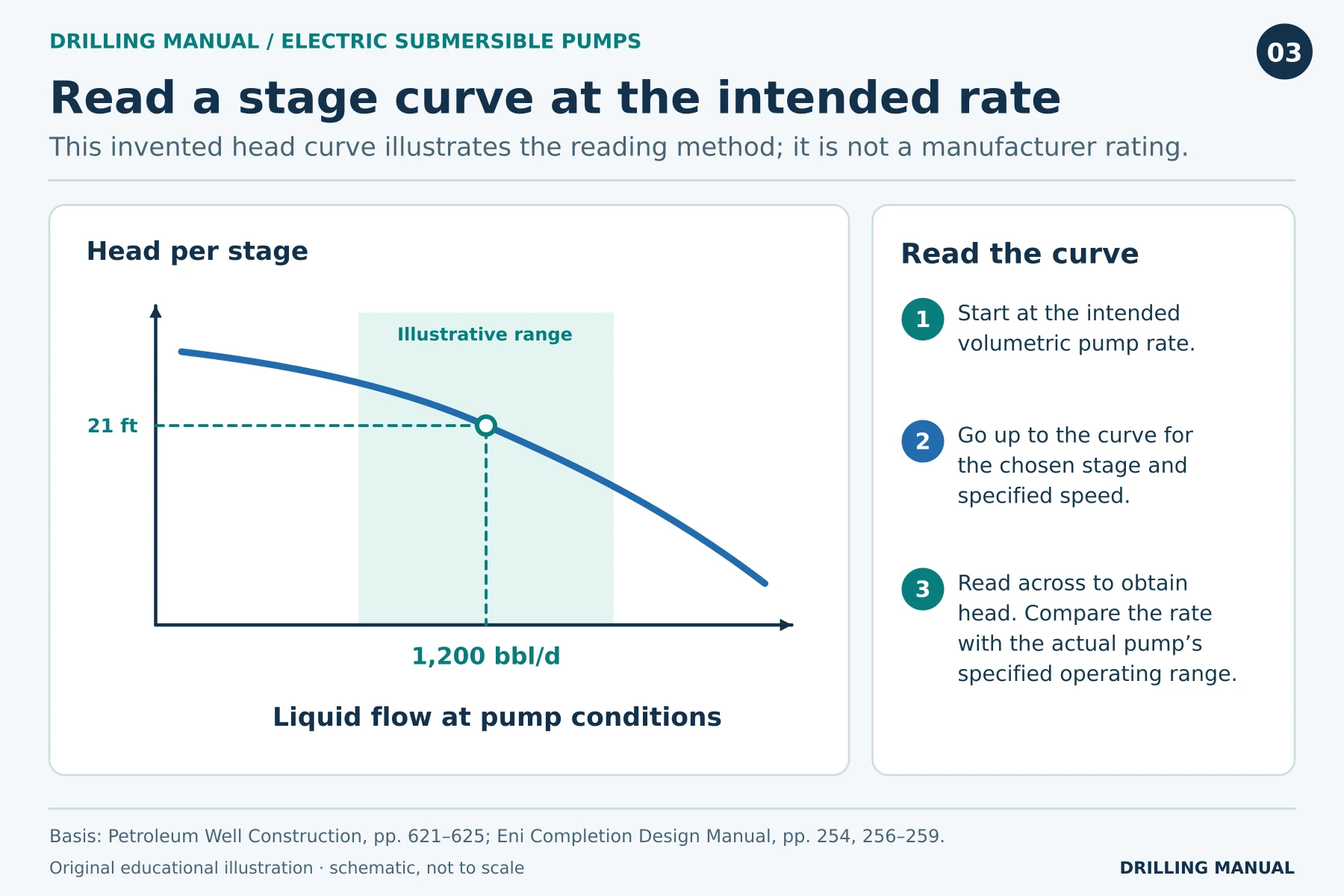
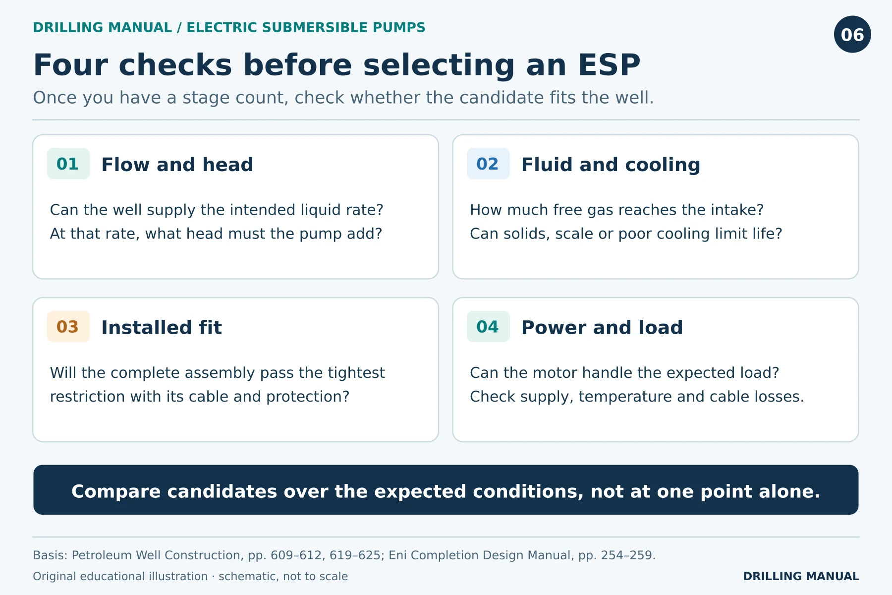
Start with the rate at pump conditions and the curve for the specified pump design and speed. Then read the head per stage at that rate. Also check the recommended operating range, required shaft power and efficiency information for that design. If you move to a different rate on the curve, however, you are sizing for a different duty. [1], [2]
Then check what the well requires. The discharge must support the fluid column, overcome friction along the tubing and deliver fluid against the surface pressure. However, fluid already reaches the intake with some pressure. Therefore, subtract intake pressure from required discharge pressure and express the difference as head on a consistent fluid basis. If the intake lies above the perforations, its pressure need not equal the flowing bottomhole pressure at the producing interval. [1], [2]
For instance, suppose surface backpressure rises while the target rate and intake conditions remain the same. The required discharge pressure increases even though the pump has not moved. Conversely, if reservoir inflow declines, the old target rate may no longer be sustainable at an acceptable intake pressure. In other words, a pump curve describes the equipment; finding the operating point also requires the well’s response. [1], [2]
Where is the best efficiency point on an electric submersible pump curve?
The best efficiency point (BEP) is the rate at which the pump’s efficiency curve peaks for the specified speed and test fluid. It is a point on the curve; the recommended flow range is a band. First locate the expected duty within that band, then read head, efficiency and shaft power at the same rate. If the fluid is appreciably more viscous than the test water, use performance data corrected for that fluid before selecting the stages. [1]
Worked Example: Calculate the Number of ESP Stages
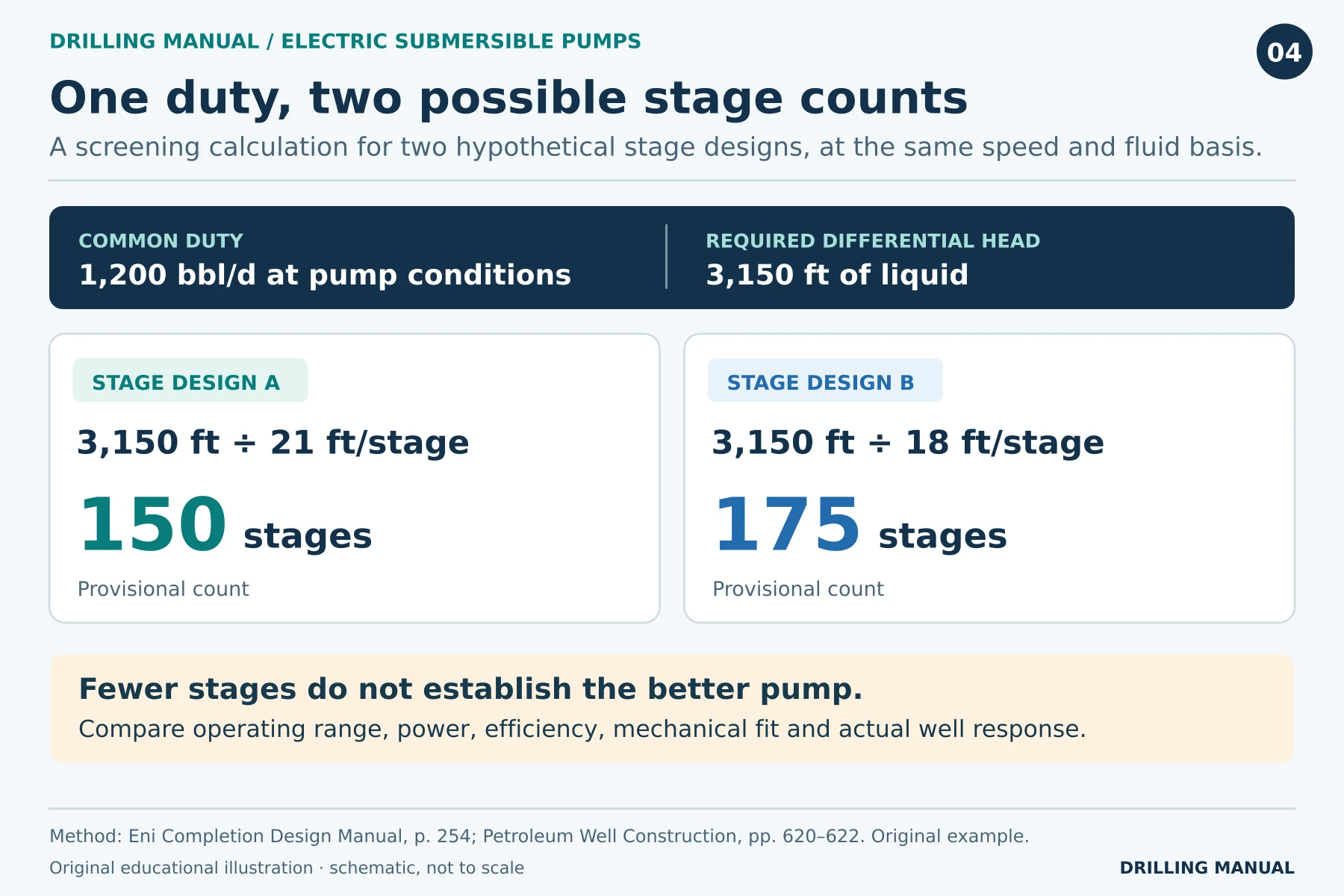
Assume a liquid rate of 1,200 bbl/day at pump conditions and a required total dynamic head of 3,150 ft. For this example, assume the liquid volume stays constant through the stages. To compare the two designs fairly, keep rate, speed and fluid conditions the same. These figures are teaching inputs, not catalog ratings. [1], [2]
Estimated stages = required total dynamic head ÷ head per stage at the design rate.
| Candidate pump design | Head per stage at 1,200 bbl/day | Calculation | Estimated stages |
|---|---|---|---|
| A | 21 ft/stage | 3,150 ÷ 21 | 150 |
| B | 18 ft/stage | 3,150 ÷ 18 | 175 |
As a cross-check, 150 × 21 and 175 × 18 both give 3,150 ft. Candidate A develops more head per stage at the stated duty. However, the smaller count tells us nothing about whether A uses less power, fits the casing or will run longer. For that comparison, bring in the power and efficiency curves, motor loading, available configurations and installation dimensions. [1], [2]
How much shaft power would each pump need?
Keep the same example, assume water, and add a second piece of curve information: 0.32 hp per stage for A and 0.26 hp per stage for B. These are illustrative readings at 1,200 bbl/day and the same speed. A needs 150 × 0.32 = 48 hp at the pump shaft; B needs 175 × 0.26 = 45.5 hp. In this example, the design with more stages actually needs less shaft power. Neither value is the electrical power drawn at surface. Motor selection still requires the motor load and speed data, and electrical design must account for voltage lost in the cable. [1]
Electric Submersible Pump Selection: Applications and Limits
Liquid rate and water cut. An electric submersible pump is worth considering where a well supplies a substantial liquid stream, including oil wells producing a large proportion of water. Size for the fluid the pump must handle, rather than oil sales alone. Also distinguish a surface liquid rate from the volume at the intake: free gas and fluid properties can change the relationship. [1], [2]
Free gas and motor cooling. Free gas entering the centrifugal stages can reduce their effectiveness. For example, a rotary separator can divert some free gas toward the casing annulus if the completion allows that route. Even so, cooling needs a separate check: does produced fluid travel past the motor? If fluid would otherwise enter the intake without sweeping the motor, the design may require a shroud to direct it. [1], [2]
What is the difference between gas lock and pump-off?
Gas interference reduces the head the pump can develop. If drawdown takes intake pressure below the oil’s bubble point, gas can come out of solution. If enough free gas gathers in the stages, the pump may no longer develop the head needed to deliver liquid: this is gas lock. A separator diverts part of the gas before it enters the pump; a gas-handling stage instead conditions the mixture. Neither guarantees that gas lock cannot occur. [1], [4]
Cavitation is a different mechanism. Vapor bubbles form where local liquid pressure falls to its vapor pressure and collapse as pressure recovers. By contrast, in gas lock it is the accumulation of free gas that interrupts liquid delivery. Low reservoir pressure alone tells you neither which mechanism is present nor whether the pump is damaged. [4], [5]
Pump-off has a different cause: at the operating speed, the pump tries to take more liquid than the formation delivers. As a result, the producing fluid level can fall toward the intake. The same well can experience both conditions, but a drop in rate alone does not distinguish them. Intake pressure or fluid-level history and the production trend help separate the two explanations. [1], [4]
Sand, scale and temperature. Abrasive solids can wear the pump, while scale deposits on impellers can impair performance. Hardened components or sand control may help in a suitable completion, but they do not remove the need to assess solids production. Similarly, cable insulation and motor cooling must suit the expected temperature. [1], [2]
Will the equipment fit, and can power reach the motor?
Before selecting a configuration, check the pump, motor, cable and protection hardware against the casing or liner restrictions. Even if the pump has enough stages, the complete assembly must still pass through the narrowest restriction. Cable voltage loss and motor load must also be checked against the available supply. In addition, the cable needs a sealed passage through the wellhead to preserve well integrity. A completion drawing should show the cable route and any required packer feedthrough. [1], [2]
The cable must also survive the trip. A restriction may clear the pump body yet leave the cable exposed to crushing, particularly at a dogleg. In a deviated or horizontal well, that makes the shape of the setting interval as important as its depth. An ESP can serve a horizontal well without sitting in the lateral: a suitable straight section above it may house the unit. There is no single maximum setting depth or inclination for every ESP: the required head, temperature, cable voltage loss, motor cooling and bending along the assembly all matter. [1], [2]
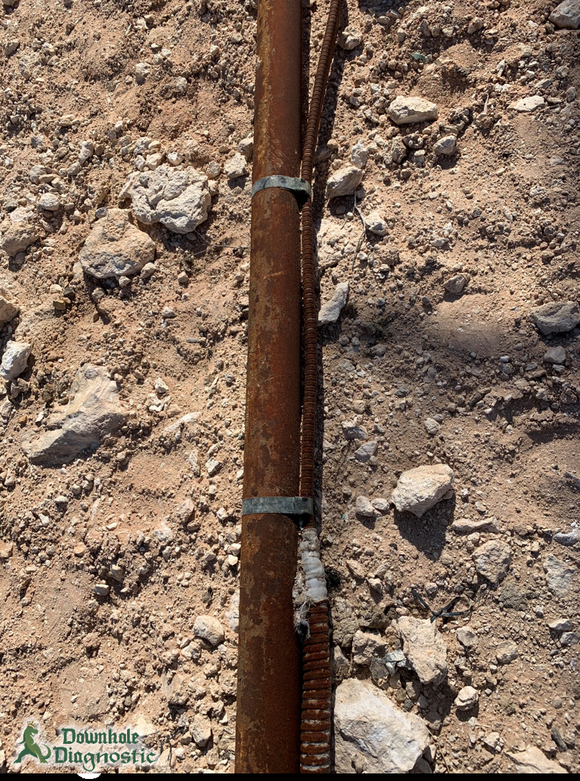
Photo: Downhole Diagnostic.
Operating Limitations and Practical Rules of Thumb
When well conditions change, a variable-speed drive gives the operator some flexibility. The approximate affinity relationships compare corresponding points on the curves for the same pump under similar conditions. At those points, rate varies with speed, head with speed squared and power with speed cubed. However, actual well rate need not change in direct proportion to frequency. Reservoir delivery, the tubing system and motor limits still determine what can be sustained. [1], [2]
- Quote head with a rate and speed. For example, “21 ft per stage” is incomplete without the curve conditions.
- Keep intake and discharge separate. Setting depth alone gives neither the intake pressure nor the head the pump must supply.
- Check motor cooling independently of pump head. Even when the stage count gives sufficient head, the flow past the motor still needs a separate velocity check.
- Compare measurements taken under like conditions. A change in produced liquid rate deserves a check of drive settings, wellhead backpressure and inflow before it is attributed to pump wear.
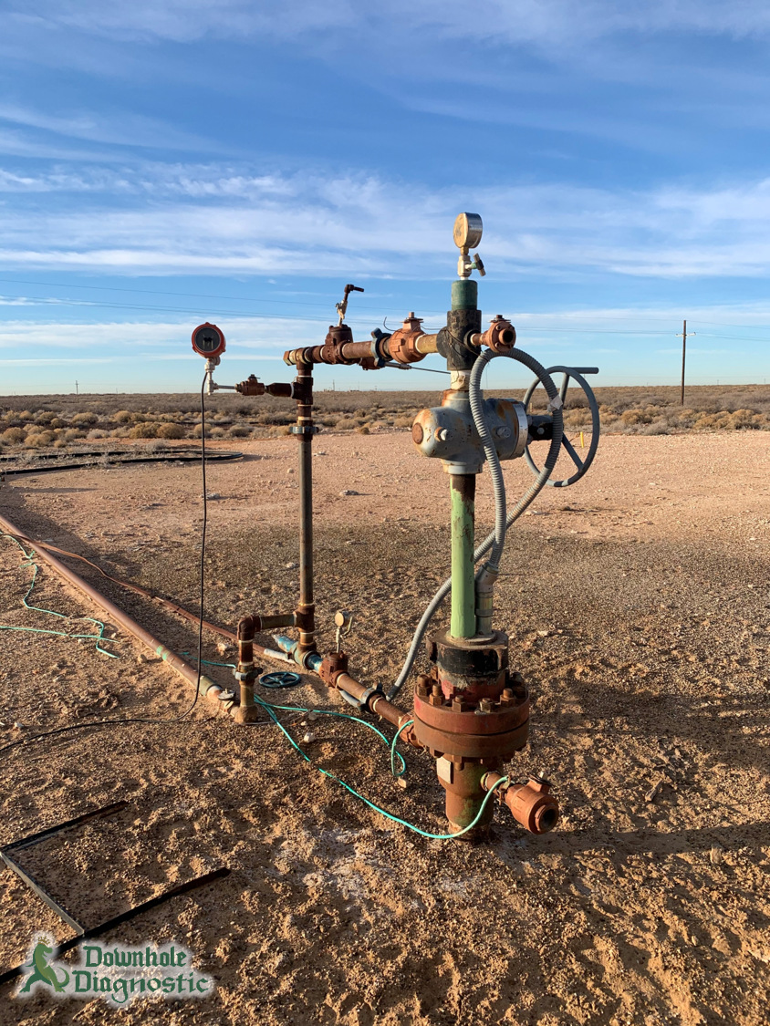
Photo: Downhole Diagnostic.
Monitoring an Electric Submersible Pump: What Does a Change in Current Mean?
A fall in oil rate does not establish that the pump has failed. First compare oil, water and gas rates with the earlier well test; a change in water cut can hide what happened to total liquid. Then line up drive frequency, wellhead pressure and motor current with that test. A surface ammeter measures the current drawn by the motor, not the liquid rate. Where a downhole gauge is installed, compare flowing pressure and temperature too, noting the gauge location. Fluid-level measurements can help when intake pressure is unavailable. [1], [4]
| Observation | What to compare before assigning a cause |
|---|---|
| Current fluctuates while the liquid rate falls | Compare gas production and intake conditions with the voltage history. Alternating gas and liquid, emulsion, or an unstable power supply can all disturb the current trace. |
| The unit repeatedly stops as the fluid level falls | Compare the estimated inflow with the pump capacity at the recorded speed. The combination warrants a pump-off check; a stop by itself does not prove it. |
| The unit is pulled earlier than expected | Record the actual days on production and why it was pulled. Inspect the recovered cable, pump and protector; distinguish a failed component from a planned change in pump size. |
A current chart tells you when motor current changed. A voltage fluctuation can change current even at a steady load. The well test, pressure history and voltage record help explain why. This distinction matters especially after an overload trip: the record is evidence for investigating the cause, not a reason to restart the unit. [4]
Common Electric Submersible Pump Questions
Does an ESP produce oil or total liquid?
It moves the fluid admitted at its intake. For example, in a well with a high water cut, much of the liquid lifted can be water. Consequently, a rise in total liquid does not by itself establish an equal rise in oil production. An ESP can also move liquids in a gas well: one specialized completion pumps water down into a receiving zone. In that application the pump moves liquid; it does not act as a gas compressor. [1], [2]
Does adding stages increase flow or pressure?
At a specified liquid rate and speed, adding stages increases the head available. The resulting well rate may change, but it must be found from the new pump and well-system balance. Consequently, stage count alone gives no production forecast. [1], [2]
Is an ESP the same as gas lift?
No. An ESP transfers shaft power to the produced fluid. Gas lift instead injects gas to lighten the flowing column, while a rod pump uses a surface drive and rod string to work a downhole pump. For method selection, compare the expected liquid rate, free gas and power supply. A stable, high-liquid-rate well with electric power is an ESP candidate; existing compression may favor gas lift, and rod pumping merits consideration at a lower liquid rate. No single method wins on rate alone. [1], [2]
How is an electric submersible pump installed and retrieved?
In a conventional completion, the assembly runs on the production tubing with its power cable fastened alongside. Consequently, replacing that assembly normally means pulling the tubing. Cable-suspended and coiled-tubing-deployed systems have different retrieval arrangements. If later work requires wireline access below a conventional pump, a Y-tool can provide a bypass where casing clearance allows. That access must be designed into the completion. [1], [2], [4]
How long does an ESP last, and what does it cost?
There is no single useful figure for all wells. Compare run days in wells with similar solids, temperature, fluid and power conditions. Count a pump pulled for resizing separately from one pulled after a cable or motor failure; otherwise the comparison can make reliability look worse than it was. For cost, compare equipment and installation, electricity over the expected run, and the cost of retrieving and replacing the assembly if it fails. A price or life estimate for a particular well needs its own equipment quote and operating history. [2], [4]
Book references
- Petroleum Well Construction, John Wiley & Sons, Halliburton educational version. Chapter 13, pp. 592–597 (artificial-lift comparison), 608–615 and 618–619 (equipment, gas handling, bypass access, trajectory and deployment), 619–625 (head, stage and shaft-power selection, fluid correction and speed); p. 625 introduces gas lift.
- ENI–Agip, Completion Design Manual, STAP-P-1-M-7100, revision 0, 28 June 1999. Section 10.2, pp. 254–259 (Eq. 10.A, deployment, clearance and operating constraints); section 10.7, pp. 268–271 (method selection, reliability and costs).
- IADC Drilling Manual, 12th edition, 2015. “Pumps,” p. PM–2 (physical PDF p. 798). Used for the general relationship between centrifugal-pump head, liquid density and pressure.
- ENI–Agip, Completion Procedures Manual, STAP-P-1-M-7120, revision 0, 28 June 1999. Section 10.1, pp. 89–95 (installation, retrieval, operating records, gas lock and pump-off).
- Rig Pumps & Circulating, p. 28 (centrifugal-pump energy conversion) and p. 32, Fig. 32 (vapor formation and collapse).