What Is Well Integrity?
Well integrity is the condition in which a well contains its fluids and prevents unintended movement into other formations or the surface environment. Managing it means designing, verifying, monitoring and maintaining the barriers, equipment and working practices needed to preserve that containment throughout the well’s life. [1]
A well integrity assessment therefore looks beyond whether the well is producing normally. It considers potential pressure sources, possible flow paths, the barriers on those paths and the evidence that those barriers can perform their intended duties. The operating limits and current condition of the well belong in the same assessment. [1]
Well Integrity, Well Control and Borehole Stability
Although these subjects are related, they answer different engineering questions. ISO 16530-1:2017 addresses lifecycle integrity management. Its scope excludes dynamic well-control activities and the stability of the drilled open hole. The comparison below follows that edition’s scope. Terminology can vary between documents. [1]
| Subject | Main question | Typical focus |
|---|---|---|
| Well integrity | How is containment established and preserved? | Barrier condition, verification, operating limits and management throughout the well lifecycle. |
| Well control | How is unintentional formation-fluid release prevented or controlled during well operations? | Dynamic operations involving equipment and systems such as BOPs, pumps and well-control fluids. |
| Borehole stability | Can the drilled open hole retain its shape? | The ability of the exposed formation to remain intact after drilling. |
Separating the subjects does not remove their operational connections. For example, a BOP can form part of a barrier arrangement during an applicable well phase. Its role must be understood within that arrangement and its verification requirements. [1]
Why Is Well Integrity Important?
The purpose is to control the risks associated with unwanted fluid movement. Those risks concern people, the environment and facilities. Containment must address subsurface communication as well as a release visible at the surface. An assessment limited to external leaks would therefore miss part of the problem. [1]
Well integrity also connects decisions made by different teams. A design assumption influences the equipment installed. Construction records then establish what was actually built and verified. Later, production, maintenance and intervention teams need that information to recognize changes and manage the well within its limits. [1]
Consequently, sound integrity management combines physical containment with competent decisions and reliable records. A schematic identifies the intended arrangement, while testing, monitoring and documented review provide evidence about its condition. Each has a purpose; none should be treated as a substitute for all the others. [1]
Applications of Well Integrity Across the Well Lifecycle
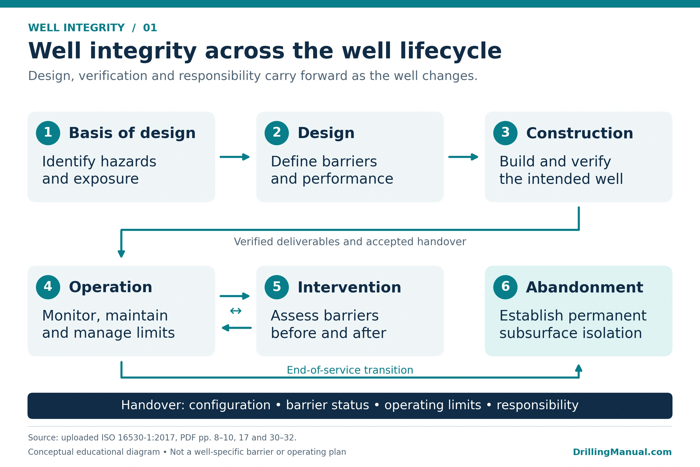
The lifecycle framework applies to producing and injection wells, including onshore, offshore and subsea installations. The particular hazards and controls vary with the well. ISO 16530-1:2017 organizes the work into six phases, with deliverables that carry information and responsibility from one phase to another. [1]
| Phase | Integrity focus | Question to resolve |
|---|---|---|
| Basis of design | Identify relevant surface and subsurface hazards. | What conditions and exposures must the design address? |
| Design | Establish barriers and controls for the anticipated well life. | Can the proposed arrangement withstand the expected conditions? |
| Construction | Build and verify the intended well; assess deviations. | What was installed, and what evidence confirms its performance? |
| Operation | Monitor, maintain and manage the well within defined limits. | Does the current condition remain consistent with those limits? |
| Intervention | Assess barriers around work that changes containment. | What barriers apply before, during and after the work? |
| Abandonment | Establish verified permanent isolation. | How will unwanted future fluid movement be prevented? |
Handover Between Well Phases
When a well moves between operation and intervention, its containment arrangement and the responsible team can change. The handover should therefore identify the current configuration, barrier status, operating limits and known hazards. Updated records allow the receiving team to work from the well’s actual condition. [1]
This also explains why abandonment planning belongs early in the lifecycle. Design, construction and maintenance choices affect whether the required isolation can later be established and verified. Waiting until the final operation to identify those constraints can leave important information or access requirements unresolved. [1] [2]
Suspended Wells and Permanent Abandonment
A shut-in or suspended well is not equivalent to a permanently abandoned well. A shut-in or suspended well instead needs monitoring appropriate to its risk and a defined plan for future use or abandonment. Its non-producing status does not remove the need to understand the barriers and possible pressure communication. [1]
Permanent abandonment has a different objective: lasting subsurface isolation, without an intention to re-enter the well. The final isolation arrangement should not depend on routine inspections to retain integrity, although an operator or regulator may require post-abandonment inspections. [1]
Well Barriers: Elements, Envelopes and Potential Flow Paths
A Component Versus a Complete Barrier Envelope
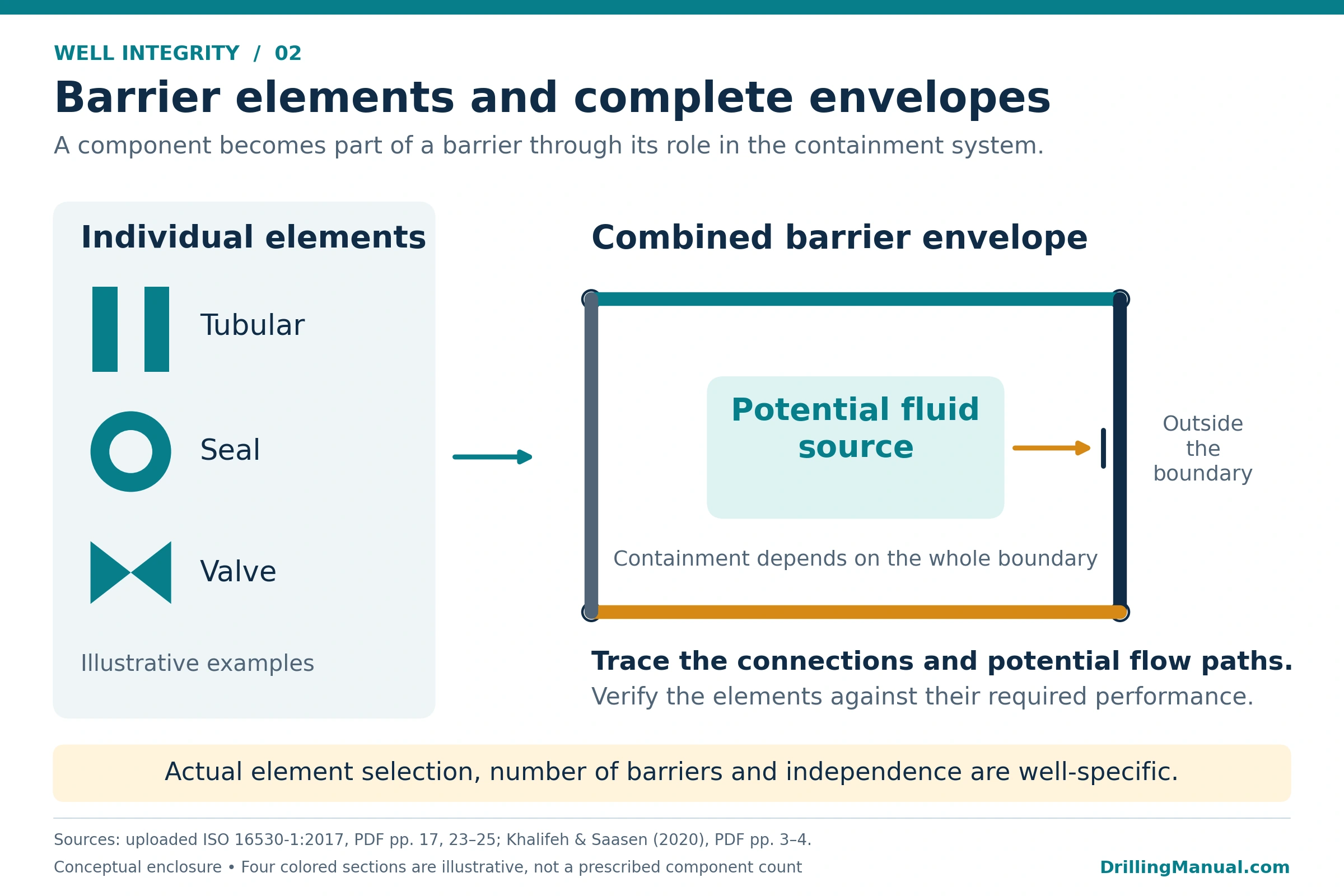
A well barrier element is a component contributing to containment. A well barrier consists of one or more elements working together. The term barrier envelope helps describe the complete enclosure against a potential source of flow. An individual element may not provide that enclosure on its own. [1] [2]
Casing, cement, tubing, packers, seals and valves can contribute to barrier arrangements, depending on the well phase and configuration. However, a list of installed equipment does not establish the condition of the complete system. The assessment must consider connections, possible routes around an element, verification evidence and any elements shared between barriers. [1]
Primary and Secondary Arrangements in Their Well Context
The primary barrier is generally the first containment arrangement exposed to the pressure source. A secondary arrangement provides additional containment if the primary arrangement fails. Which components perform those roles depends on the operation. Consequently, one fixed equipment list cannot describe every drilling, completion, production or intervention configuration. [1] [2]
ISO 16530-1:2017 recommends at least two independently verified barriers along potential uncontrolled-flow paths where practicable. Where that is impracticable, it recommends a risk assessment to determine whether a single-barrier arrangement provides acceptable containment risk. This calls for a documented assessment of the particular well and its potential flow paths. [1]
A well barrier schematic should show the arrangement and distinguish planned, installed and verified status. It should also identify potential inflow sources, relevant limits, verification requirements and shared elements. Together, these details make the drawing useful for engineering review and handover. [1]
How Completion Fluids Contribute to Well Integrity
Completion fluids can contribute to pressure support and, in an appropriate arrangement, form part of the barrier system. Annular fluids also require consideration of their interaction with the tubulars and seals. Fluid selection and control must therefore address both pressure conditions and material compatibility. [1] [2]
Changes in annular fluid type, density or volume affect the interpretation of pressure behavior and operating limits. They therefore belong in the integrity records. Nevertheless, fluid present in an annulus is not automatically a complete, verified barrier. Its intended function must be established for that well and phase. [1]
An Impaired Element Versus a Connected Release Path
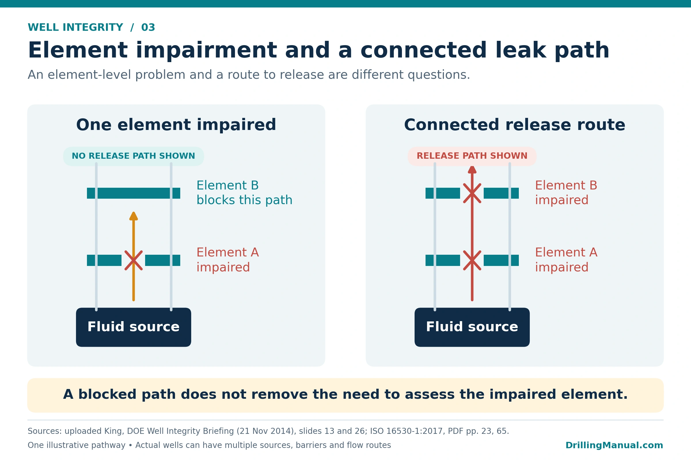
A failed element and a connected release route are different findings. Another containment element may interrupt the route from a pressure source to the environment. If failures connect through the relevant boundaries, however, they can create a continuous pathway. The comparison concerns a particular route, not every component anywhere in the well. [3]
Absence of a demonstrated external leak does not make the impaired element acceptable. Its failure changes the integrity condition and requires assessment of the remaining barriers, possible communication and consequences. Repair priorities and operating decisions must follow that assessment. [1]
Factors Affecting Well Integrity and Common Failure Modes
Well integrity depends on the loads applied, the environment around each element, and the condition of the assembled system. Design and construction quality establish the starting point. Fluid exposure, operating changes, degradation and maintenance then influence its condition over time. [1] [3]
| Factor or mechanism | Potential effect | Information needed for assessment |
|---|---|---|
| Corrosion and fluid incompatibility | Damage to structural or pressure-containing materials; deterioration of susceptible seals. | Materials, fluid composition, exposure conditions and inspection history. |
| Erosion and mechanical wear | Material loss that affects element condition. | Solids, flow conditions, operating history and available measurements. |
| Pressure, temperature and mechanical loading | Loads or repeated cycling that challenge the arrangement. | Casing design and other load assumptions, actual operating conditions and equipment limits. |
| Cement, packer or seal impairment | Communication between a pressure source and another well space. | Configuration, verification records and diagnostic evidence. |
| Formation movement or subsidence | Additional loading and possible damage to casing or supporting structures. | Subsurface conditions, relevant field changes and monitoring results. |
The table groups assessment topics rather than ranking their frequency. A mechanism important in one well may have little relevance to another. Its significance depends on the actual materials, configuration, exposure and operating history. [1]
Include Surface Equipment and Access Constraints
The review should include the wellhead, tree, hanger seals, valves and associated connections, alongside the downhole tubulars and cement. Mechanical damage, corrosion, wear or incorrect valve position can affect the containment arrangement. Surface equipment should therefore remain part of the same barrier and monitoring assessment. [1]
Some conditions also affect the ability to investigate or restore integrity. For example, scale or damaged casing can restrict access needed for abandonment work. Identify these restrictions during planning. Their presence, however, does not prove that an external release has occurred. [2]
Design, Maintenance and Information Quality
Changes of use, repairs and altered operating conditions can make an earlier assessment incomplete. When those conditions change, the records should capture the change and the management-of-change process should evaluate its implications. Reliable information and competent review are therefore part of maintaining well integrity, alongside the physical condition of the equipment. [1] [3]
Well Integrity Monitoring and Evaluation
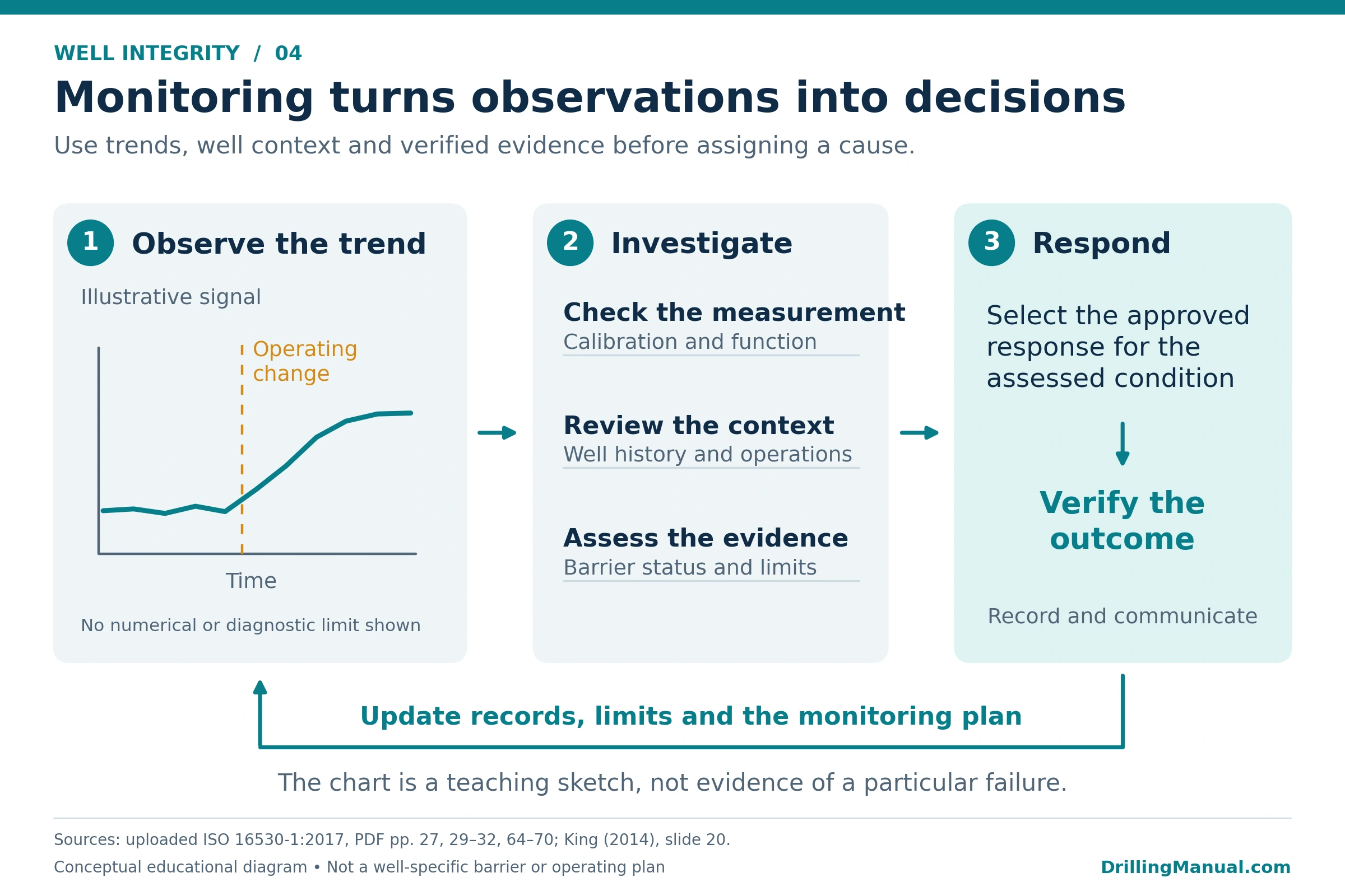
Monitoring establishes how the well behaves over time. Testing checks a defined performance requirement. Investigation brings the observations, well history and supporting evidence together to assess an anomaly. Together, these activities support the assessment without giving a single reading more meaning than it can support. [1]
Baselines, Trends and Operating History
A baseline provides a reference for subsequent observations. Compare trends with operating changes, previous tests and the documented limits. King’s well integrity briefing emphasizes the value of retaining a baseline, maintaining a trend history and knowing the asset’s working limits. [3]
Depending on the well, the evidence can include tubing and annulus pressures, equipment inspections, corrosion surveillance and diagnostic logs. Recording fluid additions or removals also helps explain changes in an annulus. Instrument calibration and function checks are part of evaluating the quality of those observations. [1]
Investigation and Diagnostic Evidence
When a result departs from the expected behavior, review the measurement and the well’s operating history. Then examine the barrier configuration, potential communication paths and relevant limits. Logging can provide information about components that are difficult to assess from the surface. However, interpretation must address the particular integrity question. [1] See cement bond logging for background on that diagnostic method.
How Often Should Well Integrity Be Monitored or Tested?
The operator defines the monitoring and maintenance program. Frequency can reflect the likelihood and consequences of barrier degradation, equipment history and the time available to respond. Temperature changes, service changes, manufacturer guidance and applicable requirements also influence the program. [1]
Review the schedule when actual performance differs from expectations. Repeated anomalies or changing conditions may show that the existing program needs adjustment. A frequency shown in an example table should not become a universal interval for unrelated wells. [1]
Annulus Pressure and Well Integrity
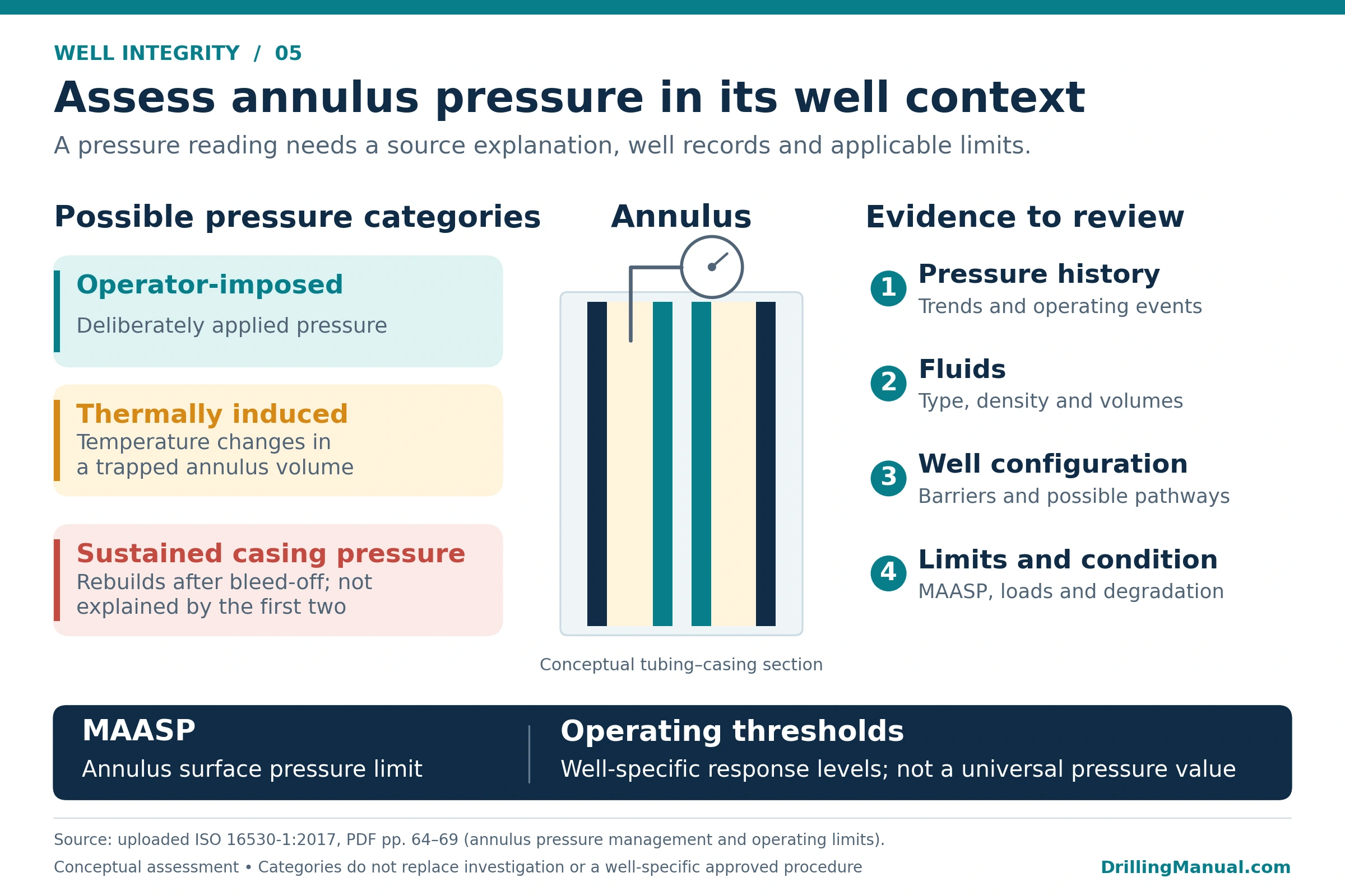
Annulus pressure needs interpretation within the well’s configuration and operating history. A pressure reading alone does not identify its source. ISO 16530-1:2017 distinguishes three categories that help frame the investigation. [1]
Three Categories of Annulus Pressure
| Category | Meaning | Assessment focus |
|---|---|---|
| Operator-imposed pressure | Pressure deliberately applied as part of the operating arrangement. | Confirm the intended purpose and the limits applicable to that arrangement. |
| Thermally induced pressure | A pressure response to temperature changes within a trapped annulus volume. | Review temperature and operating history alongside the annulus loading conditions. |
| Sustained casing pressure | Pressure that rebuilds after bleed-off and is not explained by imposed pressure or thermal effects. | Examine the design, possible communication paths and condition of the relevant barriers. |
Sustained pressure can occur in arrangements that allow it by design. In other cases, it can indicate communication associated with an impaired barrier element. Equally, identifying a thermal contribution does not remove the need to assess pressure against the well’s limits. [1]
What Information Is Needed for Assessment?
Useful information includes the pressure trend, fluid type and density, fluid volumes added or recovered, and recent operating changes. The current well schematic and equipment condition help define possible routes between a pressure source and an annulus. For an abnormal trend, the assessment should also consider the pressure that could develop if an impaired element deteriorates further. [1]
Diagnostic testing may form part of the investigation. However, pressure manipulation and bleed-down testing require an operator-defined procedure and risk assessment. The purpose here is to explain the evidence required, without prescribing a field test sequence. [1]
MAASP and Operating Thresholds
Maximum allowable annulus surface pressure (MAASP) is an annulus-specific surface pressure limit. Its determination considers the relevant barrier elements and any exposed formations. The calculation therefore uses the as-constructed well, component performance, fluids and formation information. It also accounts for degradation. [1]
For an accessible annulus that permits pressure management, the operating range defines the working boundaries and response thresholds. ISO 16530-1:2017 places the upper operating threshold below MAASP to provide time for corrective response. It does not establish one percentage margin suitable for every well. [1]
Review MAASP and the thresholds when their assumptions change. Examples include different annulus-fluid density, loss of tubular wall thickness, a change of well service or reservoir pressures outside the original load cases. Staying below a pressure limit does not, by itself, demonstrate that every barrier remains in acceptable condition. [1] The separate MAASP in drilling discussion has a different operating context from a full assessment of an operating well’s annuli.
Worked Interpretation Example: Pressure After Restart
Consider a hypothetical well where annulus pressure rises after restart. The reading remains below the recorded MAASP. The last valve function test passed, but the annulus-fluid history is incomplete. These observations provide a starting point for assessment; together, they do not establish the cause or an acceptable operating condition.
| Observation | What it contributes | What remains unresolved |
|---|---|---|
| Pressure rose after restart. | The timing makes the operating and temperature history relevant. | A thermal explanation needs supporting evidence; timing alone does not exclude communication. |
| Pressure is below recorded MAASP. | The reading can be compared with that stated pressure limit. | Its position relative to the operating threshold, and the continued validity of the limit, still need review. |
| The valve function test passed. | The test provides evidence about the valve’s operation. | That result does not establish sealing performance. |
| The fluid record is incomplete. | An information gap has been identified. | Fluid density and volume assumptions relevant to the assessment require confirmation. |
The assessment therefore combines the records, actual barrier status, relevant limits and appropriate verification. The authorized engineering review determines the response under the operator’s program. This example does not authorize continued operation or prescribe pressure manipulation. [1]
Well Integrity Testing: What Does Each Test Verify?
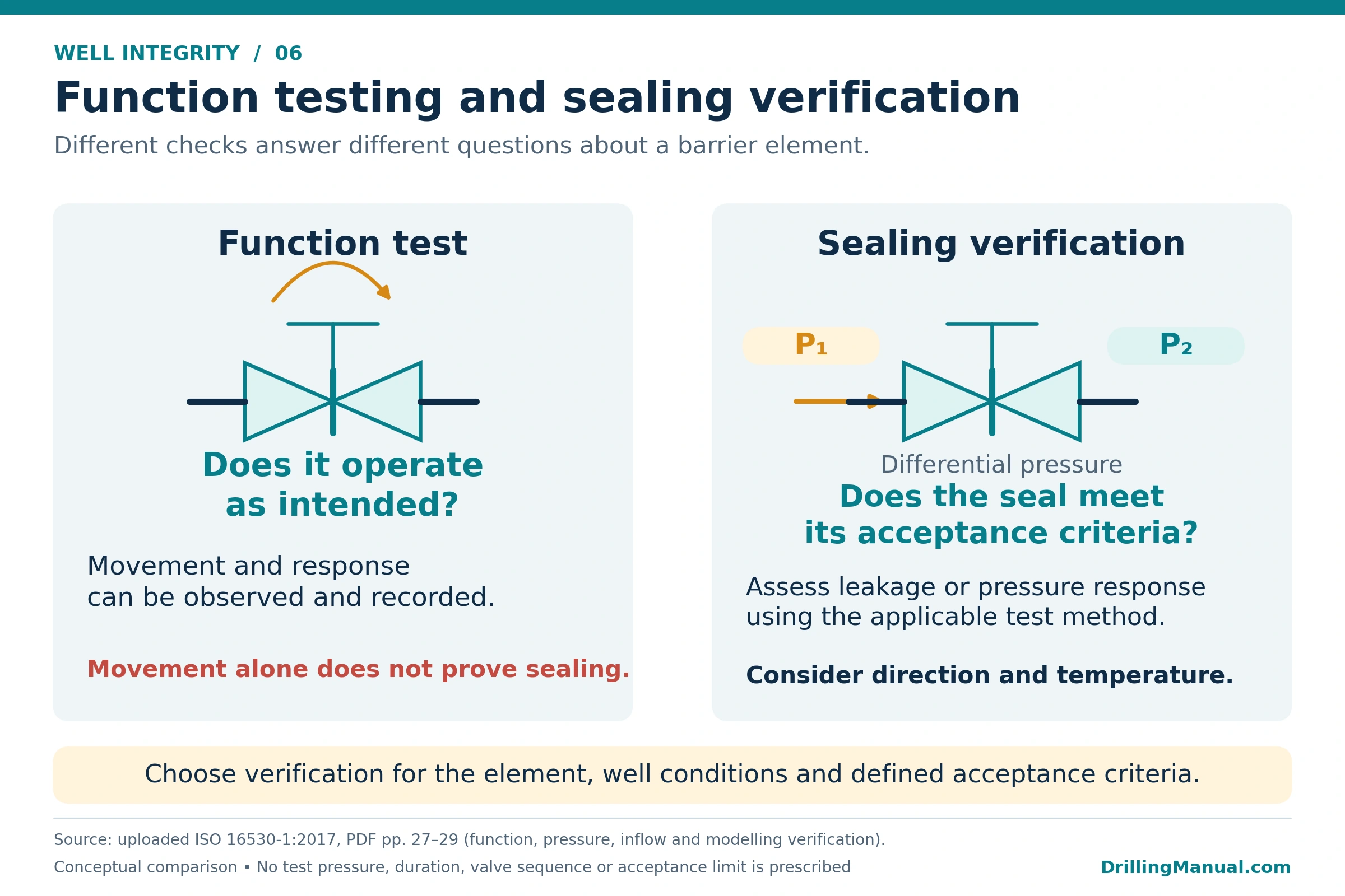
Well integrity testing provides evidence about a defined element and its required performance. First, identify the question the test must answer: does the equipment operate, does it seal, or can it withstand the relevant load? The result must then be assessed against the selected method, test conditions and acceptance criteria. [1]
Function Testing, Pressure Testing and Inflow Testing
| Test | Main question | Limit of the evidence |
|---|---|---|
| Function test | Does the element or system operate as intended? | Valve movement or response does not establish its leakage performance. |
| Pressure test | Does the component meet the relevant mechanical and sealing criteria under an applied pressure? | The result relates to the tested conditions, pressure direction and assessment method. |
| Inflow test | Does the barrier seal against a differential created using an existing pressure source? | A valve may close successfully without demonstrating every requirement of its actuation system. |
In a pressure test, the pressure comes from a known applied source. An inflow test uses an existing source, such as reservoir pressure, to establish the differential across the element. These methods therefore require a defined test arrangement and an appropriate interpretation of the response. [1]
Acceptance Criteria and Verification Limits
Direction matters because a component’s sealing behavior may depend on the direction of the pressure differential. Temperature changes can also alter the observed pressure response and complicate leakage interpretation. Consequently, a recorded pressure change needs an explanation before it becomes a conclusion about barrier condition. [1]
Some elements cannot be fully tested during operation. Their verification may instead involve suitable modeling or qualification at the design stage. ISO 16530-1:2017 also recognizes circumstances where leak testing is impractical and function testing alone may be accepted. That allowance does not make movement evidence equivalent to leakage evidence. [1]
The verification method should match the element and its performance standard. For that reason, this overview cannot supply one test pressure, hold time or allowable leak rate for every component and well. [1] The separate guide to BOP pressure and function testing provides equipment-specific background.
Well Integrity Management Systems: Responsibilities and Records
A well integrity management system, or WIMS, connects technical requirements with the people and processes that implement them. It covers risk assessment, barrier performance, verification, records, change management, improvement and audit. Clear responsibilities make these activities accountable throughout the well’s life. [1]
Accountable Roles and Competence
The operator defines who collects information, evaluates the well, approves changes and follows up outstanding actions. Personnel need competence appropriate to their assigned tasks and the well’s lifecycle phase. A responsibility matrix can clarify the interfaces, although its positions and authority levels must suit the organization. [1]
What Should the Integrity Record Contain?
A practical record brings the following information together: [1]
- Configuration: the current well and barrier schematics, including recorded changes.
- Performance: applicable criteria, operating limits and their supporting assumptions.
- Evidence: test results, inspections, pressure histories, fluid analyses and diagnostic findings.
- Work history: maintenance, repairs, replacements and equipment traceability.
- Risk and actions: identified hazards, controls, assessments and unresolved integrity issues.
- Responsibility: handover records, approved changes and the personnel accountable for follow-up.
Handover and Management of Change
Handover transfers responsibility along with the information needed to manage the well. For example, an intervention team needs the current barrier status, operating limits and known uncertainties. When the well returns to operations, the receiving team needs the verified configuration and any revised limits. [1]
Management of change assesses how a proposed modification affects integrity. It identifies the impact, evaluates risk, obtains the appropriate review and approval, and communicates the accepted change. Updating the drawings and records is part of implementing that decision. [1]
How Software Supports Well Integrity Management
Software can help organize records, retain test and maintenance histories, and make information available to authorized personnel. The underlying requirements are controlled information, traceability and reliable updates. A complete management system still depends on competent assessment, physical evidence and assigned responsibility; storing a result does not establish that the result is acceptable. [1]
How Is Well Integrity Managed in Aging Wells?
Age provides context, but condition and operating history determine the integrity questions that need attention. Review degradation, previous failures, maintenance and changes in service. Then confirm whether the documented limits still represent the well’s current condition and intended use. [1]
Condition Review, Maintenance and Remediation
An aging-well review should connect the available evidence to the barriers and their required performance. It should identify uncertainties as well as confirmed defects. Where equipment cannot meet its original specification, the operator needs a risk assessment and defined controls, together with an appropriate maintenance or remedial plan. [1]
After corrective work, verify the affected barriers against the applicable criteria. Next, update the intervention records with the resulting configuration, verification results and any changes to operating limits. Handover carries that information into the next operating phase. [1] For equipment-specific background, see the guide to casing repair.
Continued Use, Suspension or Abandonment
The design life and actual service life of a well are not necessarily identical. Reaching a date alone neither demonstrates failure nor justifies continued service. If the review finds the well unsuitable for continued use, the operator needs a defined plan. The options are to rectify its condition, suspend it or abandon it. [1]
Shut-in and suspended wells also need a defined future-use review and monitoring appropriate to their risks. Leaving a well inactive does not settle its integrity obligations or its eventual disposition. [1]
Practical Rules of Thumb for Well Integrity
Use these qualitative principles when organizing an assessment. They support the well-specific program and its acceptance criteria. [1]
- Match the evidence to the question. Movement, sealing and structural performance require different forms of verification.
- Read a trend with its history. Include operating changes, fluid information and instrument checks before assigning a cause.
- Review limits when assumptions change. The original calculation may no longer represent the current well.
- Assess an impaired element even without an observed release. Absence of visible leakage does not resolve the barrier problem.
- Close the loop after corrective work. Verify the result, update the records and communicate the new status.
- Keep ownership clear. An identified issue needs an accountable assessment and follow-up process.
Limitations and Source Scope
An individual reading, inspection or test has a defined scope. Its result cannot automatically establish the condition of untested elements or every potential flow path. Well integrity evaluation combines the relevant evidence with the configuration, operating conditions and documented performance requirements. [1]
The lifecycle framework in this article follows ISO 16530-1:2017. That edition is identified deliberately; this overview does not establish the latest regulatory requirements or an operator’s approved procedure. Source examples of test criteria, maintenance intervals and calculations require their original context. [1]
The diagrams explain relationships and assessment questions. They do not specify a barrier arrangement, test program, repair method or operating authorization for an individual well.
Frequently Asked Questions About Well Integrity
Does a Passed Pressure Test Prove the Integrity of the Whole Well?
A pressure test provides evidence for the components and conditions included in that test. It does not establish the condition of every other barrier element or potential flow path. The overall assessment also needs the well configuration, relevant inspection and monitoring results, and current operating limits. [1]
Does Annulus Pressure Always Mean a Leak?
No. Imposed pressure and temperature-related pressure changes are among the possibilities. Sustained pressure requires assessment against the well’s design and condition. The reading, trend and operating history must be considered together; a pressure category alone does not establish whether the well is acceptable for continued operation. [1]
Can a Well Continue Operating After a Barrier Element Fails?
There is no general permission to continue. The operator must assess the affected element, remaining containment, potential communication and consequences under its approved requirements. That assessment determines the response, controls and repair priority. Absence of a visible release does not remove the integrity issue. [1]
Is Well Integrity Software the Same as a WIMS?
Software supports activities such as storing records, tracking work and making evidence accessible. A WIMS also assigns responsibilities and defines technical requirements, assessment, verification, change and assurance processes. The software is therefore a supporting tool within the management arrangements. [1]
How Is a Shut-In Well Different from an Abandoned Well?
A shut-in well retains a defined status and needs a plan for its future use or abandonment, with appropriate surveillance. Permanent abandonment establishes lasting isolation without an intended return to service. Simply closing a well’s valves therefore does not establish that permanent isolation. [1]
Does Reaching the Design Life Mean a Well Has Failed?
Not necessarily. Design life and actual service life can differ. The decision depends on the current condition, operating history, applicable limits and a review of suitability for further use. The review must justify the chosen plan; age alone cannot establish either failure or fitness for continued service. [1]
References
[1] International Organization for Standardization. ISO 16530-1:2017: Petroleum and natural gas industries — Well integrity — Part 1: Life cycle governance. First edition, March 2017. Principal sections used: 1, 3, 5, 7 and 9–11.
[2] Khalifeh, M., and Saasen, A. General Principles of Well Barriers. Chapter 2 in Introduction to Permanent Plug and Abandonment of Wells, Springer, 2020, pp. 11–69. DOI: 10.1007/978-3-030-39970-2_2. Relevant sections: well annuli, barrier elements and envelopes, schematics, and abandonment-planning factors.
[3] King, G. E. Well Integrity — Basics, Prevention, Monitoring, Red Flags & Repair Options. DOE Well Integrity Briefing, United States Energy Association, Washington, DC, 21 November 2014. Relevant slides include 9, 12–13, 20 and 26.