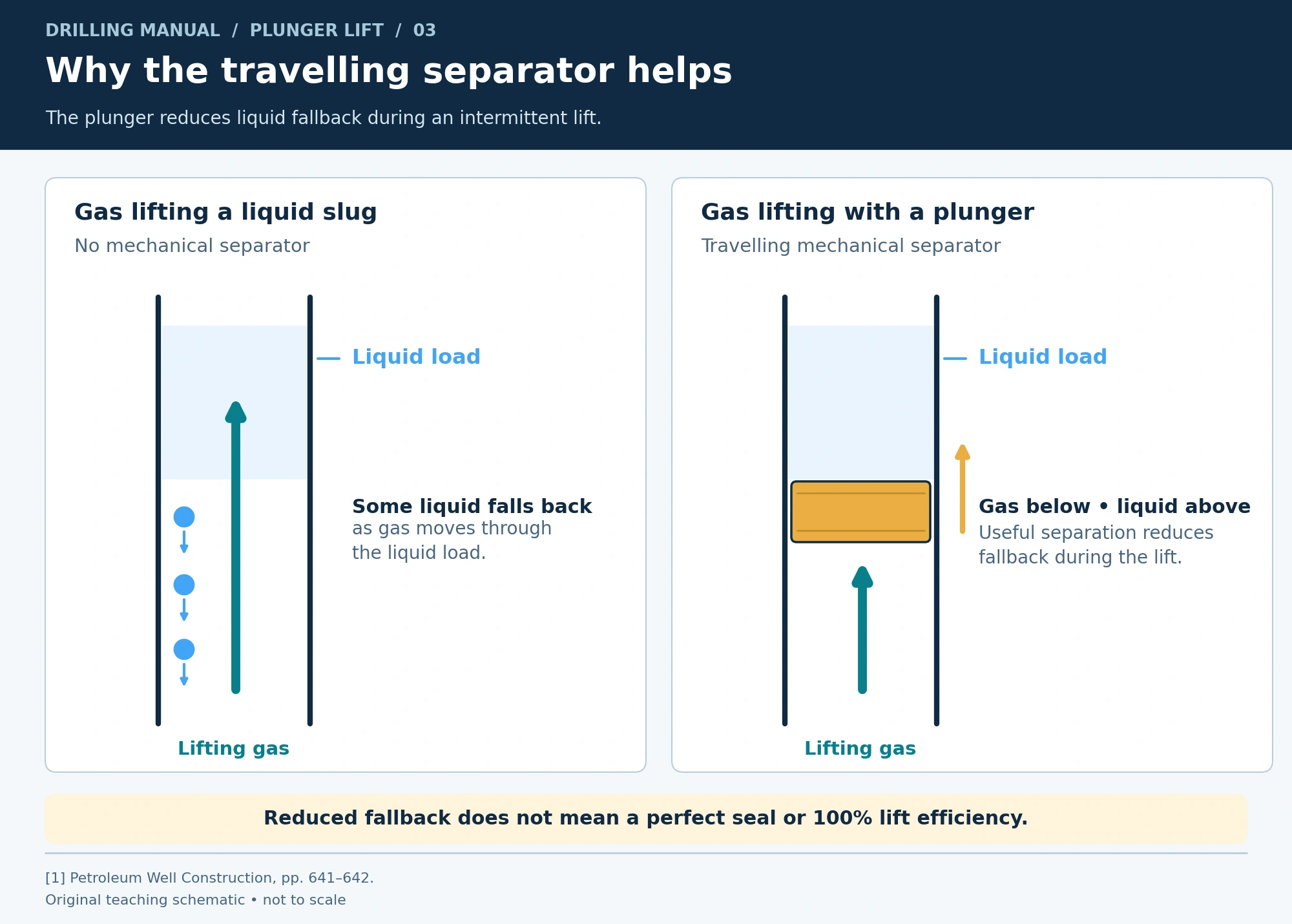
Plunger lift removes accumulated liquid by sending a free-travelling plunger up the production tubing with a liquid slug above it. During this lift, gas below the plunger supplies the energy. After the liquid reaches surface, the well produces gas before the next cycle. The plunger helps separate the lifting gas from the liquid and reduces liquid fallback. [1], [2]
That makes plunger lift useful where a gas well still has usable gas energy but struggles to unload its liquids. However, installation alone does not establish that the well can deliver the required liquid volume. Therefore, gas availability, the complete travel path and the number of successful cycles all matter. This guide explains the conventional shut-in cycle described in the references.
What Is Plunger Lift?
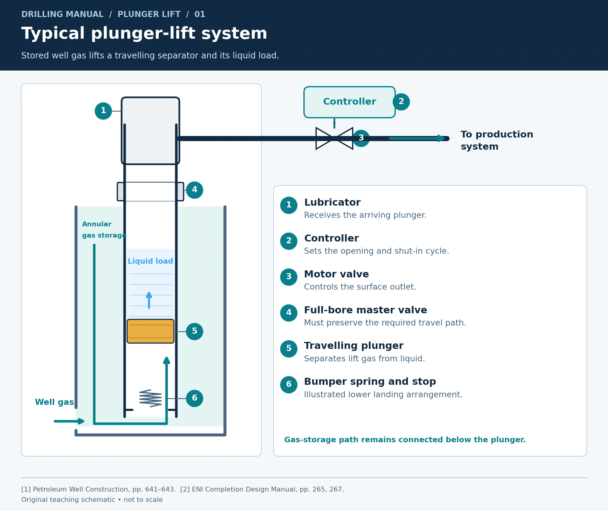
The plunger is a moving interface inside the tubing. In the arrangement described by the books, gas from the well accumulates in the tubing–casing annulus during shut-in. When the surface outlet opens, that stored energy lifts the plunger and its liquid load. Therefore, the system uses energy already available from the well unless supplementary gas is supplied. [1], [2]
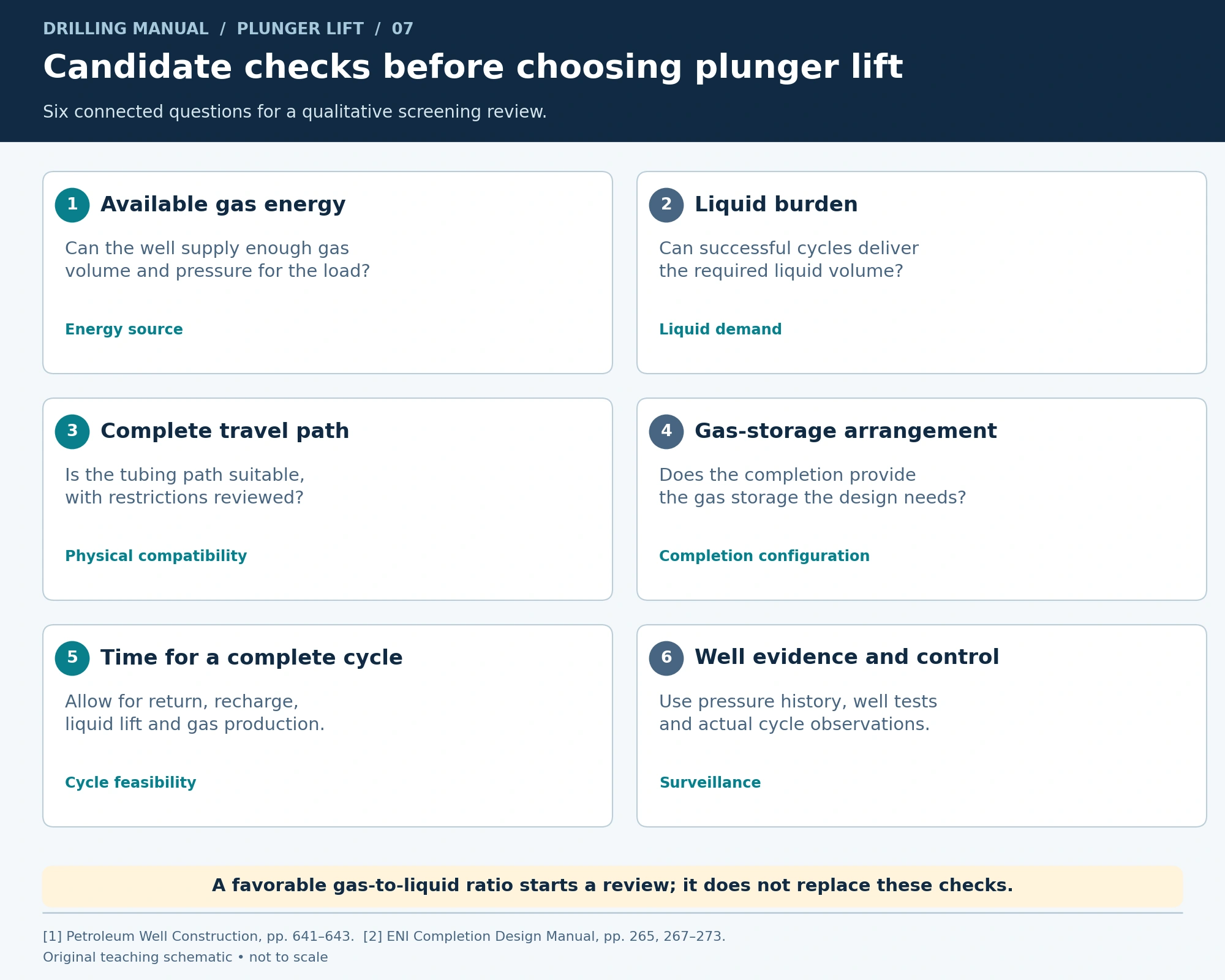
A plunger also has a place in suitable intermittent gas-lift completions. There, it reduces the fallback that occurs when lifting gas passes through or around a liquid slug. Consequently, a plunger installation and an injected-gas system are not always separate alternatives. [1]
In contrast, a temporary well-unloading treatment raises a different question. If you are evaluating a nitrogen-assisted kickoff, see the separate nitrogen lifting guide.
Typical Plunger Lift Equipment
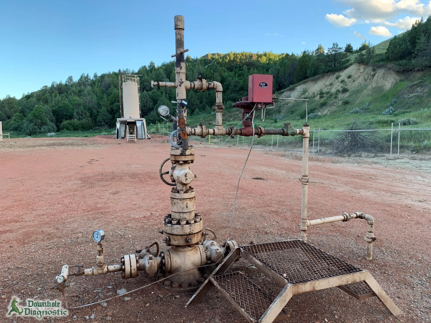
A typical installation needs both a compatible downhole travel path and a controlled surface outlet. The reference drawings include the following components; the actual completion determines the final arrangement. [1], [2]
| Component | Role in the illustrated system |
|---|---|
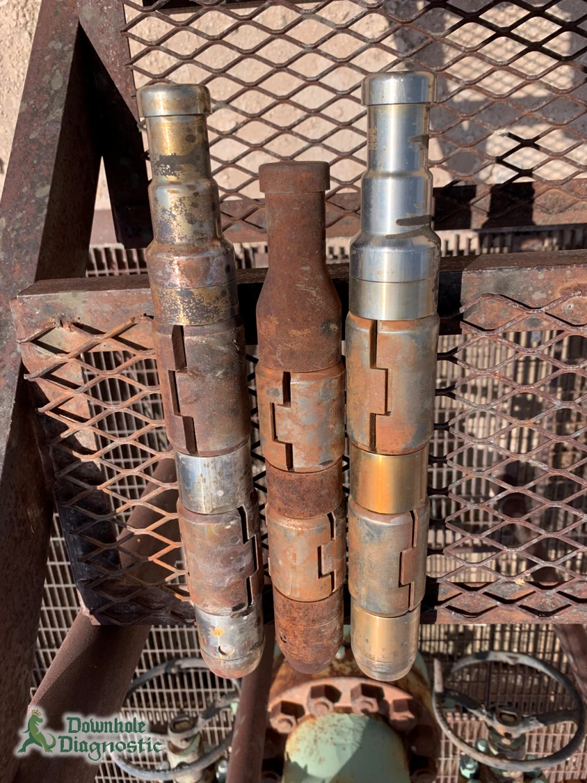
| Plunger | Travels inside the tubing and separates lifting gas from the liquid load. |
| Production tubing | Provides the travel path and carries produced fluids to surface. |
| Lubricator | Provides the upper chamber for the arriving plunger. |
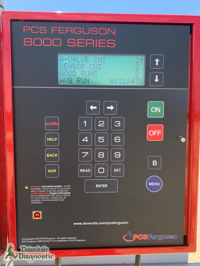
| Controller and motor valve | Control the surface opening and shut-in portions of the cycle. |
| Bumper spring and tubing stop | Provide the illustrated lower landing arrangement. |
| Annular gas volume | Stores gas energy in the conventional arrangement shown. |
The reference drawing allows a time-cycle controller or high/low-pressure control. The installed control program therefore determines the actual opening logic. The ENI drawing also shows a standing valve and a full-bore master valve. These details should be checked against the well schematic rather than treated as an equipment list that suits every well. In particular, the nominal tubing size does not describe every restriction along the plunger path. [2]
How the Plunger Lift Cycle Works
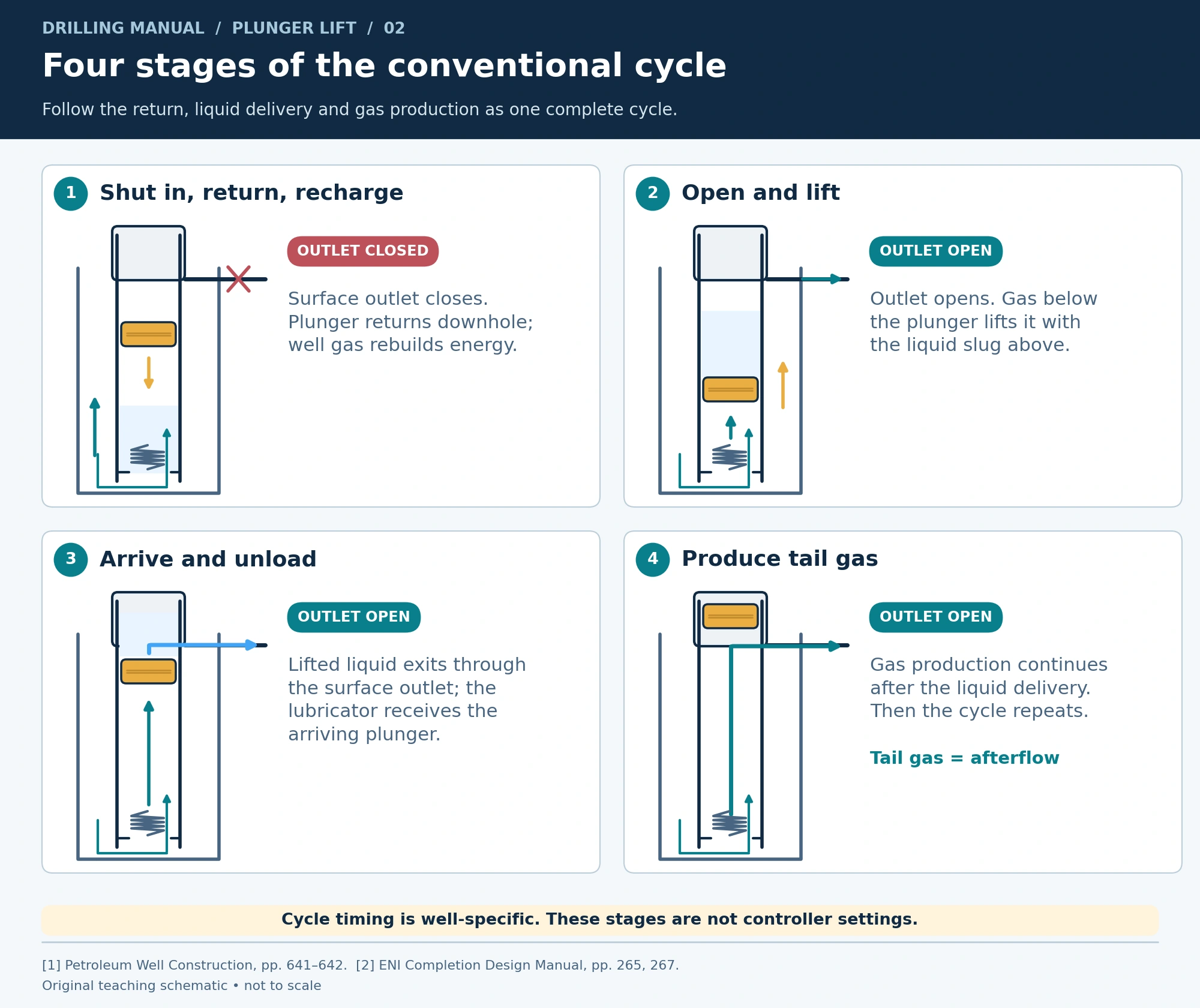
1. Shut in, return and recharge
The surface outlet closes for the conventional cycle. The plunger returns toward its lower stop while gas pressure rebuilds. Enough time is needed for both the return and preparation for the next lift. Petroleum Well Construction specifically cautions that very frequent intermittent cycles may leave too little time for the plunger to fall. [1]
2. Open and lift the liquid slug
When the outlet opens, gas below the plunger expands and drives it upward. Meanwhile, liquid travels above the moving plunger. The separator reduces fallback, but it does not ensure perfect efficiency or replace adequate gas energy. [1], [2]
3. Arrive and unload
The lifted liquid passes through the surface outlet, while the lubricator receives the arriving plunger. A completed travel event and a useful liquid delivery are related observations, but each still needs to be established from the available well data.
4. Produce tail gas, then repeat
Once the liquid is delivered, gas continues to flow. ENI describes production of the following tail gas. Afterflow is this gas-production period following liquid delivery. As liquid loading returns, another unloading cycle becomes necessary. Consequently, evaluating only the rise of the plunger overlooks a productive part of the cycle. [2]
Applications: Which Wells Suit Plunger Lift?
The main application described in the references is unloading relatively small liquid volumes from wells with a high gas-to-liquid ratio. For example, gas wells may need dewatering. A plunger also reduces liquid fallback in appropriate intermittent gas lift. [1], [2]
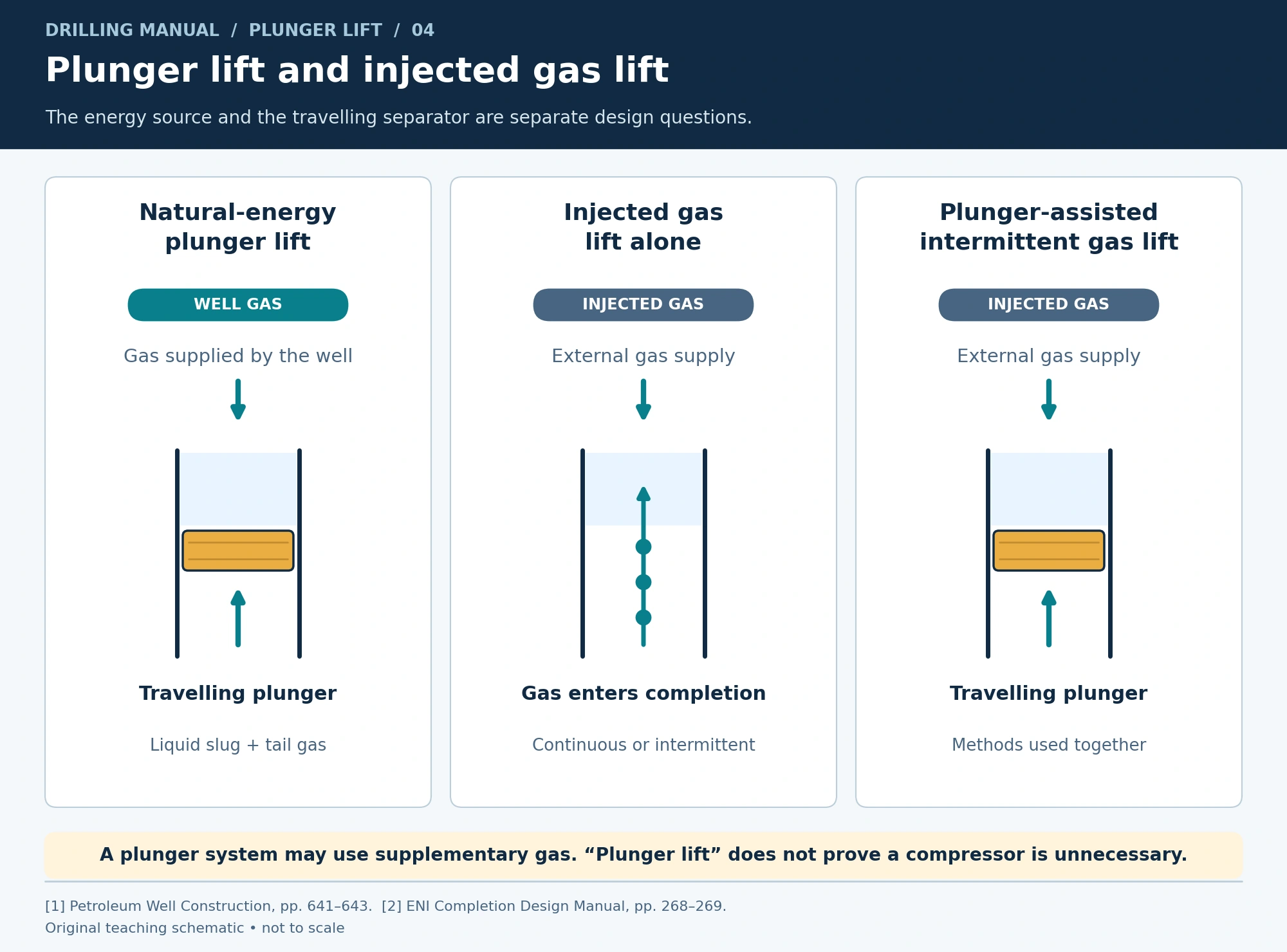
Candidate selection begins with three questions. Does the well supply enough gas volume and pressure? Can the plunger complete its travel through the actual tubing and installed devices? Can successful unloading cycles remove the required liquids without sacrificing the overall production objective?
ENI states that the tubing should be parallel and drifted. It also identifies adequate annular gas storage and good well tests and pressure charts as relevant to performance. Thus, a favorable gas–liquid ratio should start a candidate review; it should not replace one. [2]
What if the well has a packer?
Before assessing the installation, trace the gas path on the actual completion schematic. A packer can isolate the tubing–casing annulus, so the presence of annular volume alone does not establish usable storage for the illustrated cycle. For this arrangement, confirm how stored gas reaches the tubing below the plunger. [1], [2]
The references also describe supplementary gas entering through suitable gas-lift equipment. Therefore, an installed packer requires a completion-specific assessment. It is not a reason to assume the simple drawing applies unchanged or to prescribe removal of the packer. [1], [2]
Plunger Lift vs Gas Lift
| Arrangement | What supplies the lift? | Important distinction |
|---|---|---|
| Natural-energy plunger lift | The well’s own gas moves a plunger and liquid slug. | A travelling separator helps unload liquid cyclically. |
| Injected gas lift | Gas supplied to the completion assists production. | Its operating mode and gas supply need separate design. |
| Plunger-assisted intermittent gas lift | Injected gas lifts liquid with a plunger as the separator. | The two methods can work together. |
Petroleum Well Construction notes that a well with insufficient gas relative to its produced liquids may need supplementary gas. Therefore, “plunger lift” does not by itself prove that a compressor or external gas supply is unnecessary. Instead, the completion and available well energy determine that answer. [1]
For the injected-gas arrangements, the separate gas lift in oil wells guide explains continuous and intermittent operation.
Factors Affecting Plunger Lift Performance
Gas supply and liquid burden
The system needs enough gas volume and pressure to lift its load. More liquid is not simply a request for more cycles, because each lift needs energy and each return needs time. ENI identifies limited cycle count as a constraint on high-volume service. [2]
Wellhead and production-line backpressure
Also include the receiving system in the assessment. ENI explains that flowing wellhead pressure acts as backpressure on the producing well. It also requires surface offtake losses to be considered when assessing deliverability. A pressure record without the corresponding flowline conditions can therefore leave an important part of the system unexplained. [2]
For example, flowline slugging, changes in other wells sharing a line, facility problems or wax buildup can change wellhead pressure. Accordingly, review such changes alongside the cycle history. The same controller schedule can give different results when surface conditions change. [2]
Completion compatibility
A plunger must both pass through the completion and maintain useful separation between gas and liquid. For example, Petroleum Well Construction explains that an eccentric side-pocket mandrel can allow gas to bypass the moving plunger. As a result, reduced velocity can prevent the plunger from reaching surface. Some extensions have been used to span the pocket, but the book does not present this as a universal remedy. [1]

Solids, deposits and sticking
Sand can stick the plunger. Although the ENI comparison describes removal of small paraffin deposits, this does not turn the system into a general cleanout treatment. The same manual warns that hang-up or sticking can be a major operating problem. Equipment condition therefore belongs in the review alongside cycle controls. [2]
Depth and available cycle time
Longer travel and the time needed to reset constrain the number of complete cycles available. Moreover, ENI states that practices need to be tailored to each well. A cycle copied from another installation can overlook the local gas supply, liquid load and completion condition. [1], [2]
How to Review Plunger Lift Performance
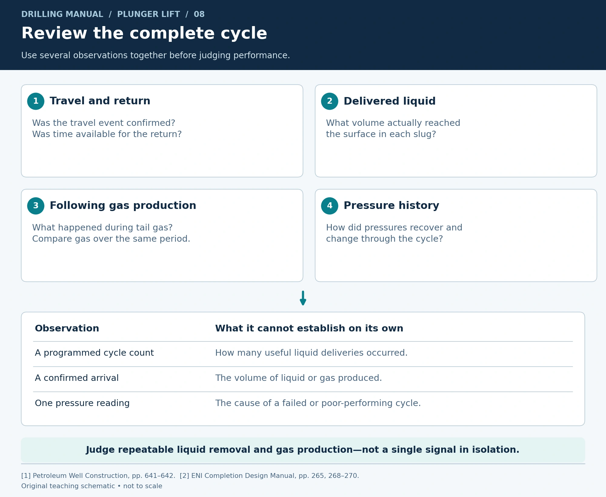
Start with the whole observation period. ENI calls for good well tests and pressure charts, as well as operating practices tailored to the well. Those requirements support a practical review of the cycle, liquid delivery and following gas production together. [2]
| Record | Question it helps answer |
|---|---|
| Planned cycles and confirmed returns | How many scheduled events completed a verified return? |
| Liquid assigned to each delivery | How much liquid did those successful events actually deliver? |
| Gas and liquid totals over the same period | Did whole-well production improve? |
| Pressure history and receiving conditions | Did the available energy or surface backpressure change? |
| Travel-path and equipment findings | Is there evidence of sticking, restriction or gas bypass? |
However, a missed return alone cannot select the remedy. For example, the books identify inadequate gas, sticking and mandrel bypass as different concerns. Compare the evidence before treating every disappointing cycle as a controller-timing problem. [1], [2]
Worked Example: Count Successful Liquid Deliveries
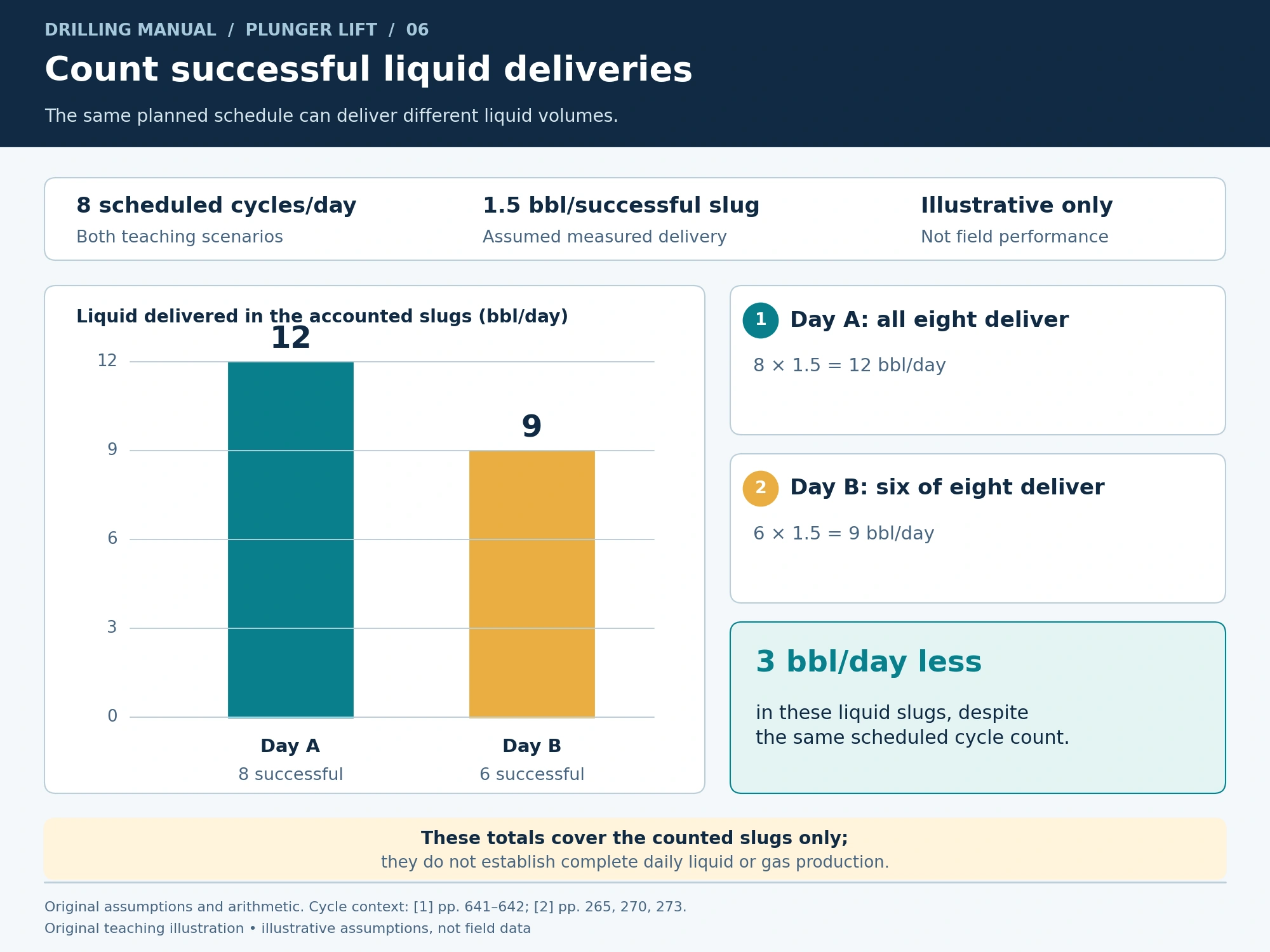
Illustrative accounting only: assume eight planned cycles in one day and 1.5 bbl of liquid delivered in each successful slug. These are invented teaching inputs, not field results or recommended operating settings.
If all eight cycles deliver that volume, the accounted liquid is 8 × 1.5 = 12 bbl/day. If only six of the eight planned cycles deliver it, the accounted amount is 6 × 1.5 = 9 bbl/day.
The second day delivers 3 bbl less in those slugs, despite the same planned cycle count. However, these totals account only for liquid assigned to the successful deliveries. Therefore, they do not establish the well’s complete daily liquid or gas production. Record the appropriate liquid and gas totals over the same observation period before comparing performance.
Plunger Lift Limitations and Practical Rules of Thumb
Plunger lift cannot create missing reservoir energy or make an incompatible tubing path suitable. Its attractive equipment cost can also change when supplementary gas and compression are required. ENI’s cost comparison is conditional; it is not a current installation quote. [1], [2]
- Assess the full cycle. Include return, pressure recovery, liquid delivery and the following gas production.
- Check the complete bore. Review restrictions and gas-bypass opportunities, not just nominal tubing diameter.
- Separate planned events from successful deliveries. The controller’s schedule is not a liquid-production measurement.
- Use pressure history with well tests. A single observation is weaker evidence than a complete cycle record.
- Keep numerical settings well-specific. The reference screening tables do not establish universal controller times or limits for every installation.
Plunger Lift Questions
What minimum pressure does plunger lift need?
These references do not establish one pressure that qualifies every well. Instead, they require adequate gas volume and pressure, suitable storage and a compatible completion. In addition, the receiving-system pressure matters. A candidate assessment must consider those conditions together. [1], [2]
What arrival speed or cycle time should I use?
Use the operating envelope and approved program for the installed equipment. The ENI manual includes historical screening values, but a general comparison table does not establish the permitted speed, impact load or controller setting for a particular installation. Its central instruction is to tailor practices to the well. [2]
How much extra gas will plunger lift produce?
No fixed increase follows from installing a plunger. The books establish the unloading mechanism, not a guaranteed production uplift. Therefore, demonstrate the result with comparable well tests and complete-period gas and liquid measurements. The worked example above is liquid-delivery accounting, not a gas-production forecast. [1], [2]
How much does a plunger-lift installation cost?
ENI describes low equipment cost when a compressor is unnecessary, while also identifying adjustment and maintenance requirements. Therefore, obtain a current scope-specific estimate covering the equipment, installation, monitoring, maintenance and any required gas supply. The books provide no current market quotation. [2]
How long will it remain useful?
The sources provide no guaranteed service life. Reassess performance when gas availability, liquid burden, equipment condition or successful-cycle capacity changes. If the system no longer meets the production objective, compare another lift arrangement using the revised well data. [1], [2]
Does this cycle apply to every plunger design?
This article explains the conventional shut-in arrangement described in the books. It does not provide a selection catalog for modern bypass or other specialized designs. Their operating sequences and limits require design-specific evidence before they can be applied to a well.
Book References
[1] Petroleum Well Construction, Chapter 13, pp. 641–643, including Figure 13-32.
[2] ENI S.p.A., Agip Division, Completion Design Manual, STAP-P-1-M-7100, revision 0, 28 June 1999: Section 5.3, p. 104; Sections 5.4.2 and 5.6.2, pp. 115 and 123; Section 10.6, p. 265; Figure 10.I, p. 267; plunger-lift columns in the comparison tables, pp. 268–273.