Nitrogen lifting with coiled tubing can restart a well when a column of liquid holds enough pressure against the producing interval to prevent inflow. The coiled tubing (CT) carries nitrogen down to a selected depth. The returning column then weighs less. As bottomhole pressure falls, reservoir fluid may begin to enter the well. [1], [2]
A separator can receive a slug of liquid during the job and the well can still stop flowing afterward. That distinction matters when reporting a kickoff: liquid recovery demonstrates unloading, whereas continued flow after nitrogen assistance ends provides evidence that the well can produce on its own under the observed conditions. [1]
Where Does the Nitrogen Go?
In the arrangement shown below, the CT runs inside the production tubing. Nitrogen travels down the bore of the CT, exits the downhole nozzle, and returns with well fluids outside the CT but inside the production tubing. By contrast, the tubing–casing annulus lies outside the production tubing. Name the space when recording annulus pressure. [1], [2]
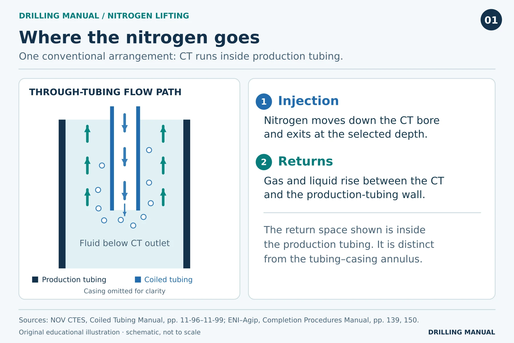
At the surface, the nitrogen pump gauge measures delivery pressure. The wellhead gauge on the return side measures pressure at another point in the circuit. For example, a change in friction inside the CT affects delivery pressure. Consequently, neither gauge on its own measures the pressure opposite the producing interval. See the coiled tubing guide for the wider equipment arrangement. [1]
Applications: When Can Nitrogen Lifting Help?
After a completion or workover. Completion or kill fluid may leave more hydrostatic head than the reservoir can overcome. In that case, temporary unloading can establish drawdown without requiring a permanent lift installation. If fluid previously entered the formation, some of it may subsequently return and add to the volume the well must carry. [1], [2]
After a producing well has been shut in. A low-pressure producer may need assistance to restart. The useful question is whether reservoir inflow can sustain production once the liquid load falls. A previous period of natural flow provides context, but it does not establish that the well will flow under today’s conditions. [1], [2]
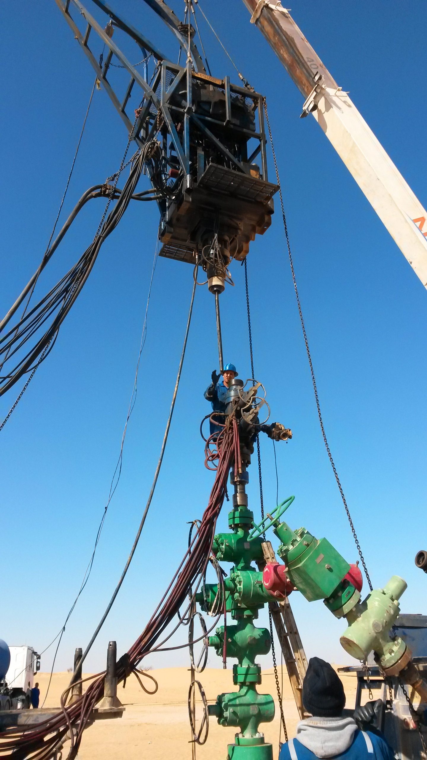
Photo: Xoref, Well intervention (2016), via Wikimedia Commons. CC BY-SA 4.0. Shown at reduced size.

During flowback after a matrix treatment. Spent treatment fluid may itself hold enough pressure against the formation to prevent natural flowback. In that case, nitrogen can help recover the liquid. The matrix treatment and the subsequent lift have separate purposes: one treats the formation; the other lightens the wellbore column. [1]
Nitrogen Lifting Calculation: What Changes in the Fluid Column?
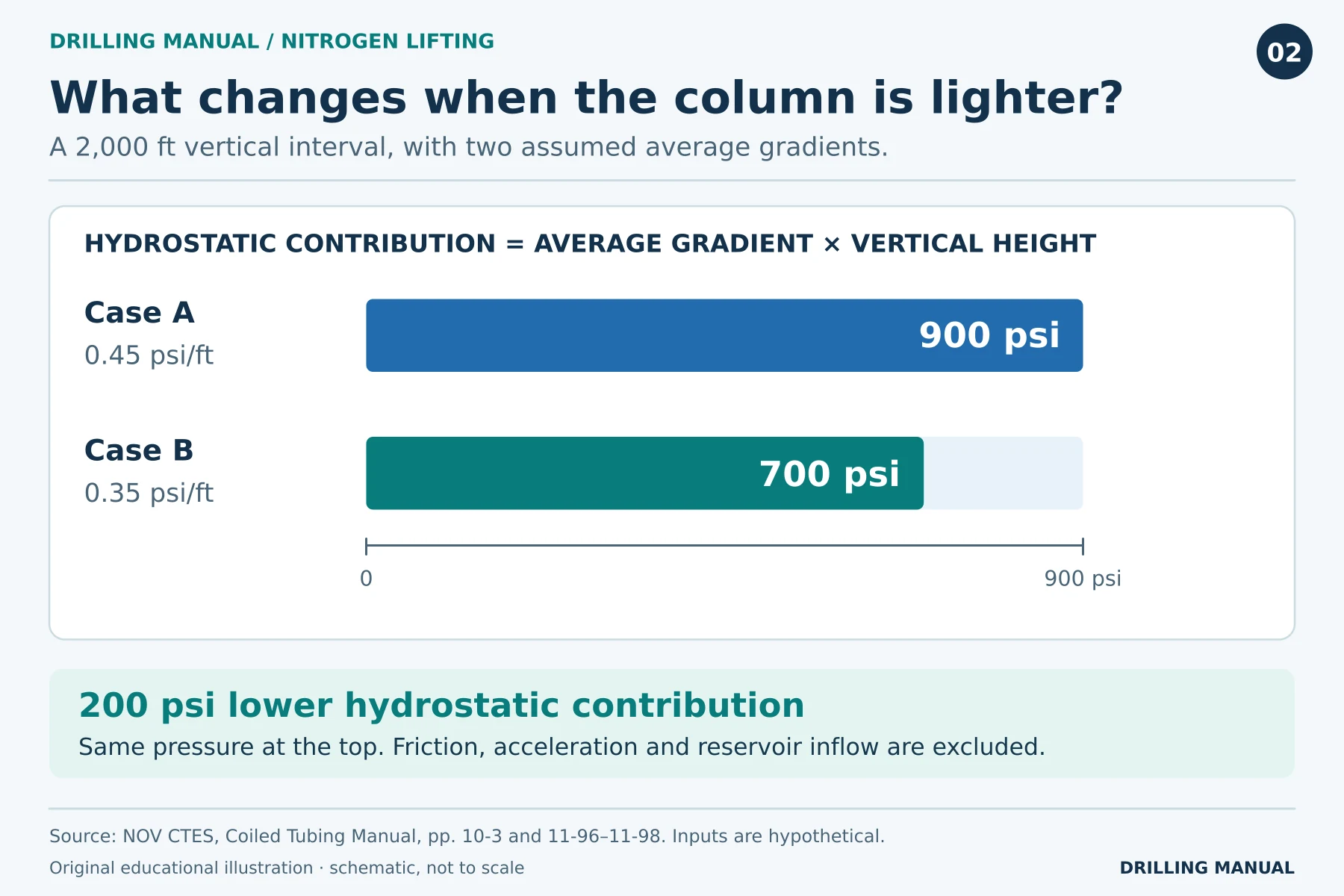
For example, take a 2,000 ft vertical interval above an injection point. Assume an average hydrostatic gradient of 0.45 psi/ft initially and 0.35 psi/ft after some liquid is lifted. Compare the columns at the same top pressure so that the difference isolates the hydrostatic term. [1]
| Column in the example | Average gradient × vertical height | Hydrostatic contribution |
|---|---|---|
| Before unloading | 0.45 psi/ft × 2,000 ft | 900 psi |
| Lighter column | 0.35 psi/ft × 2,000 ft | 700 psi |
The lighter column therefore exerts 200 psi less hydrostatic head across this interval. However, it would be incorrect to report a measured 200 psi fall in bottomhole pressure. The example omits friction, changes in surface backpressure and the rest of the well. It also says nothing about the gas rate needed to create the assumed gradient. [1]
Use true vertical height for the hydrostatic term. By contrast, the fluid follows the actual length of the flow path, including CT on the reel, when it incurs friction losses. These two lengths need not be equal. [1]
Factors Affecting Nitrogen Lifting: Rate and Depth
The injection point determines how much of the liquid column lies above the gas outlet. For example, a deeper outlet can introduce gas below more of the original liquid column. However, gas must reach the outlet against the local pressure, and the CT assembly must physically reach that position. Both the hydraulic and mechanical calculations must therefore support the target depth. [1]
The injection rate has competing effects. At one extreme, gas can slip upward through liquid without carrying enough of it to surface. This is particularly relevant in a wide return passage. Conversely, a higher rate can increase return-path friction enough to offset part of the hydrostatic benefit. In some circumstances, the resulting backpressure can drive fluid back into the formation. [1], [2]
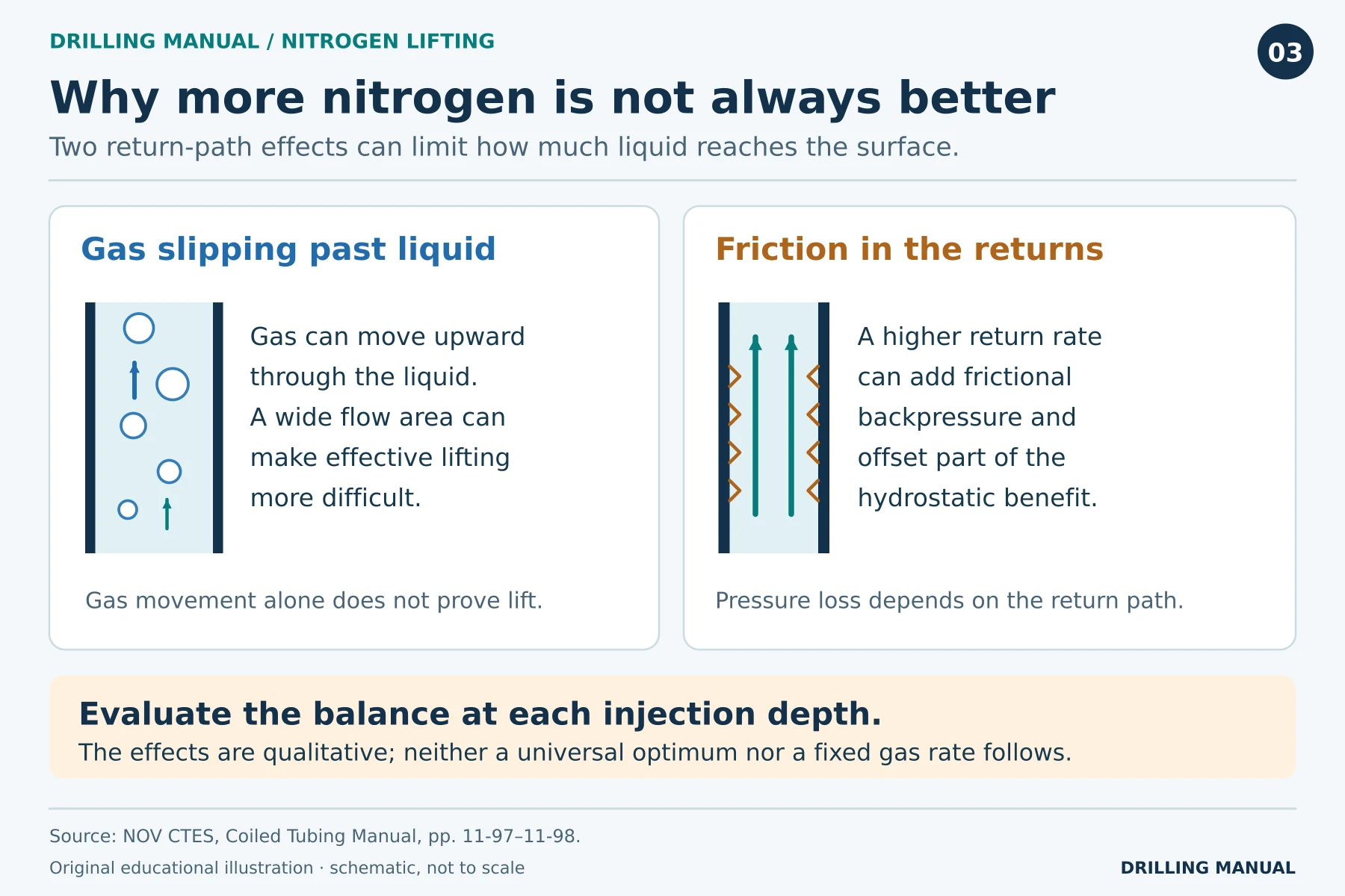
For this reason, a useful job model evaluates a range of rates at different depths. It considers both the starting fluid column and the changing conditions as liquid leaves. A single rate copied from a well of similar depth cannot capture differences in tubing geometry, fluid properties or reservoir pressure. [1]
What the Job Design Needs
First, use the completion drawing and directional survey to identify restrictions, tubing inside diameters and interval depths. Pair each producing interval with its pressure. Then describe the fluids already in the well and the route from the wellhead to the receiving equipment. These inputs establish where gas can enter, where returns can travel and what pressure opposes flow. [1], [2]
The hydraulic model addresses gas delivery, return flow and pressure. By contrast, the mechanical model answers a separate question: can the CT and its bottomhole assembly reach and leave the proposed depth within their limits? Predicted CT weight, axial forces and available overpull help distinguish a hydraulic opportunity from a mechanically impractical plan. [1]
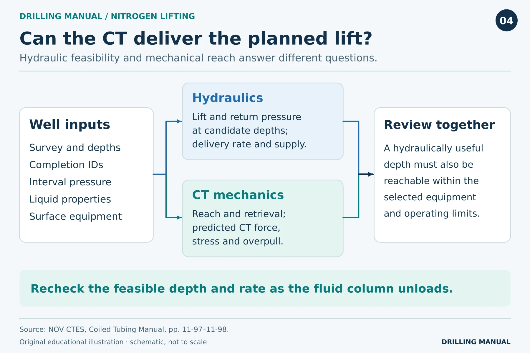
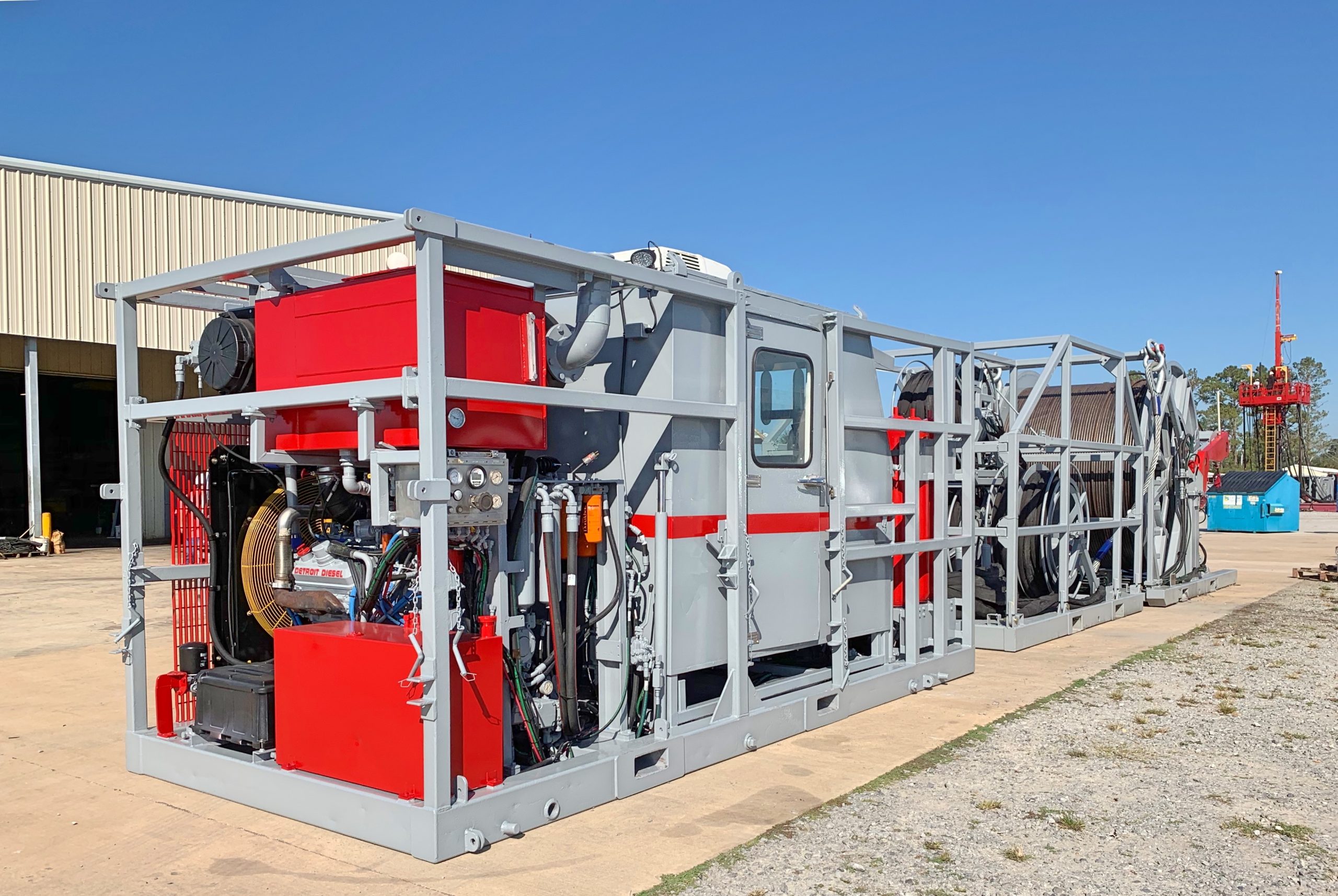
Photo: Dannybsnubbin, Coiled Tubing Unit (2019), via Wikimedia Commons. CC BY-SA 4.0. Shown at reduced size.

Nitrogen Supply and Surface Equipment
A cryogenic spread transports nitrogen as a liquid and uses a pump and thermal converter to deliver gas. An alternative spread separates nitrogen from air using a membrane and then compresses it. In both cases, the CT reel and injector handle the tubing, while a separate unit supplies nitrogen. The CT surface equipment guide shows that side of the spread. [1]
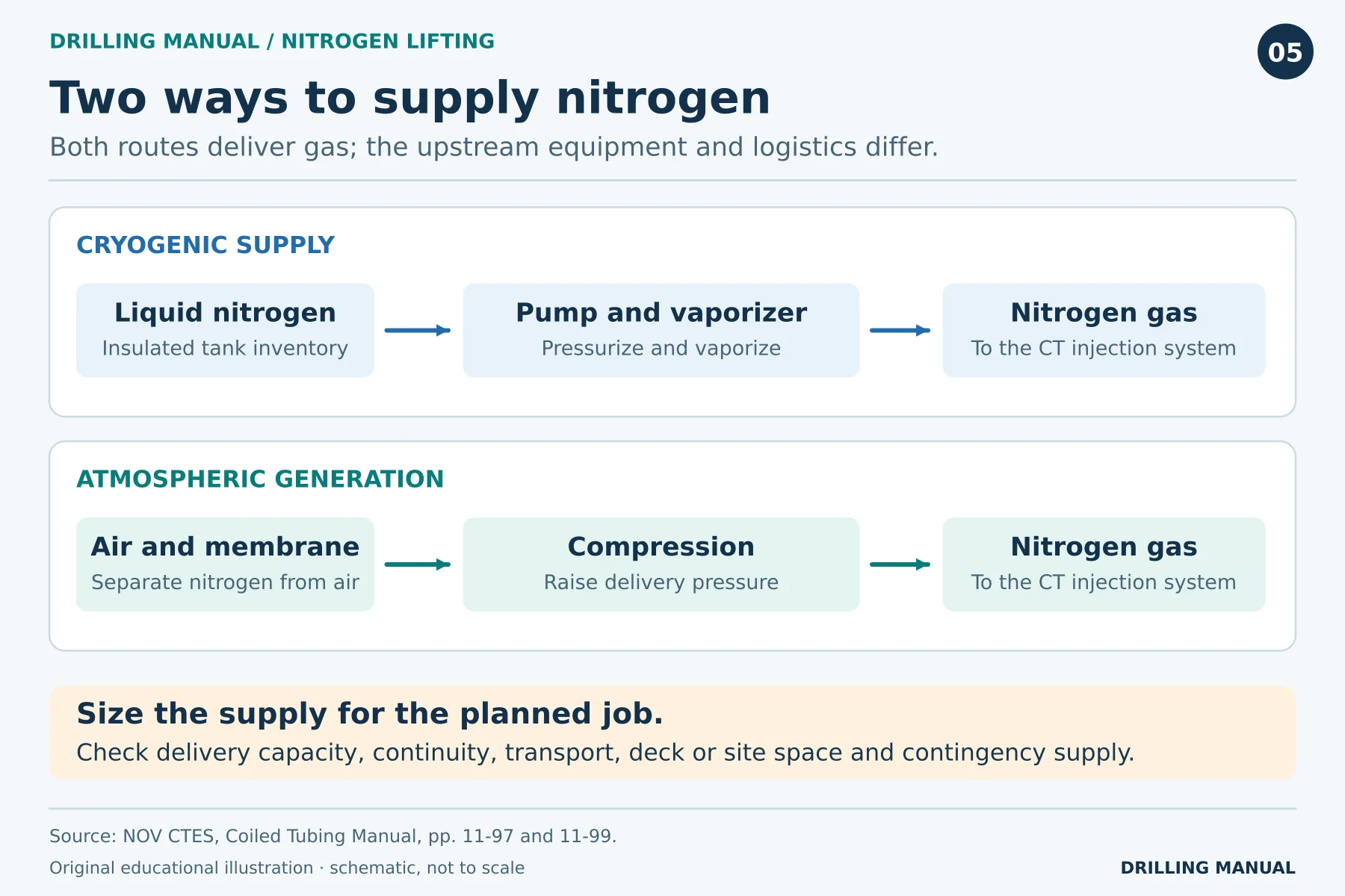
Total supply and delivery capacity answer different questions. For example, a large inventory does not establish that the equipment can deliver the modeled rate. Conversely, adequate peak capacity does not ensure enough nitrogen for the whole operation. Transport, available deck or site space, and the consequence of a supply interruption also belong in the plan. [1]
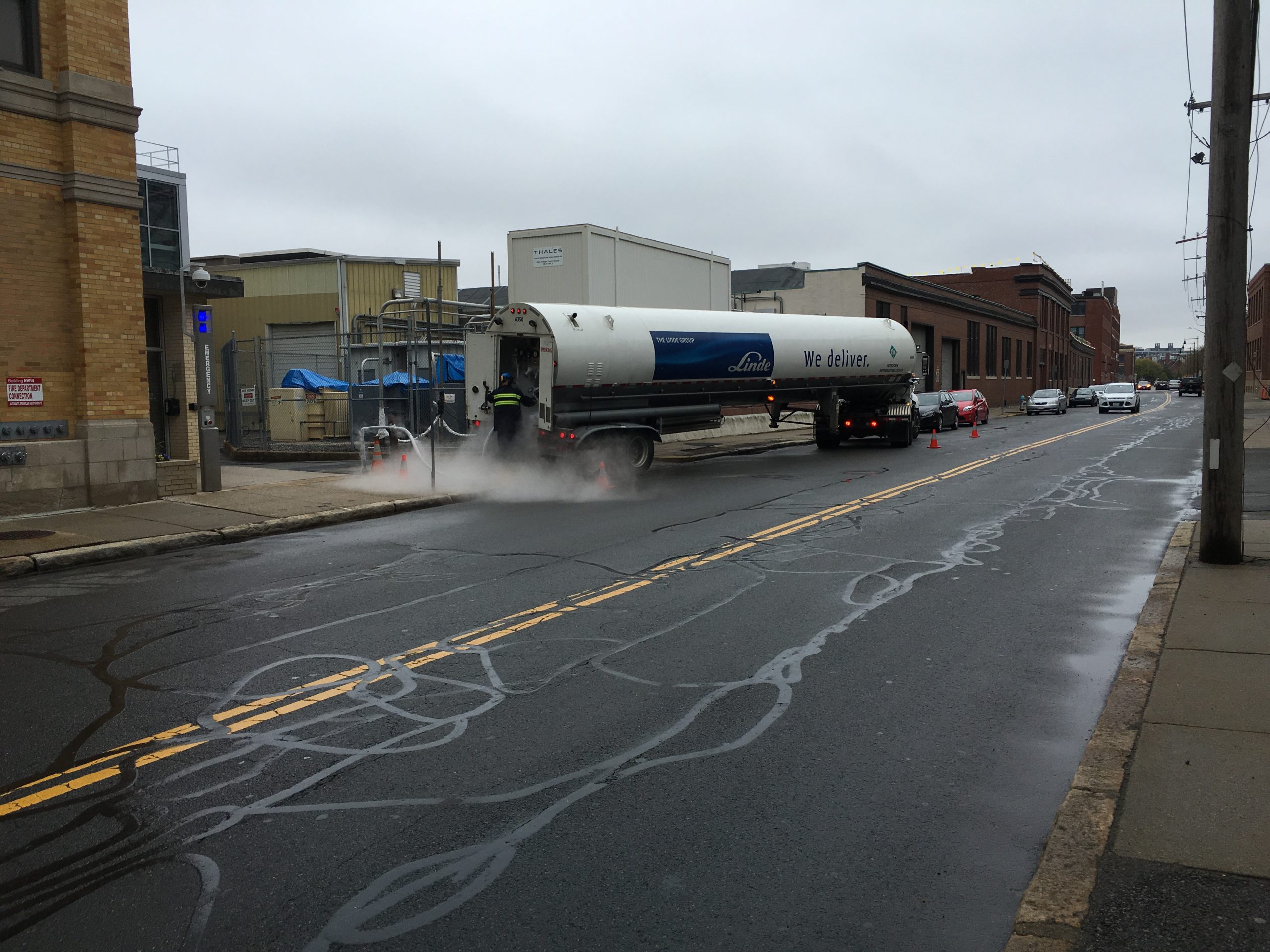
Photo: ArnoldReinhold, Liquid nitrogen delivery to MIT.agr (2016), via Wikimedia Commons. CC BY-SA 3.0. Shown at reduced size.

How to Interpret a Nitrogen Kickoff
Compare the readings on a common time scale. First, pair CT depth with indicated weight to see where the assembly was and how the string responded. Next, compare nitrogen rate with pump pressure on the delivery side. Finally, check flowing wellhead pressure, separator conditions and liquid returns at the same time. [1], [2]
| Observation | Useful interpretation | What remains uncertain |
|---|---|---|
| Liquid arrives in slugs during injection | The return stream is carrying liquid to surface. | Whether the reservoir can sustain flow without lift. |
| Pump pressure falls | A lighter column is one possible explanation. | How much of the change came from rate or CT friction. |
| Flow continues after assistance ends | Production is continuing without fresh nitrogen injection during that observation. | How long that performance will persist. |
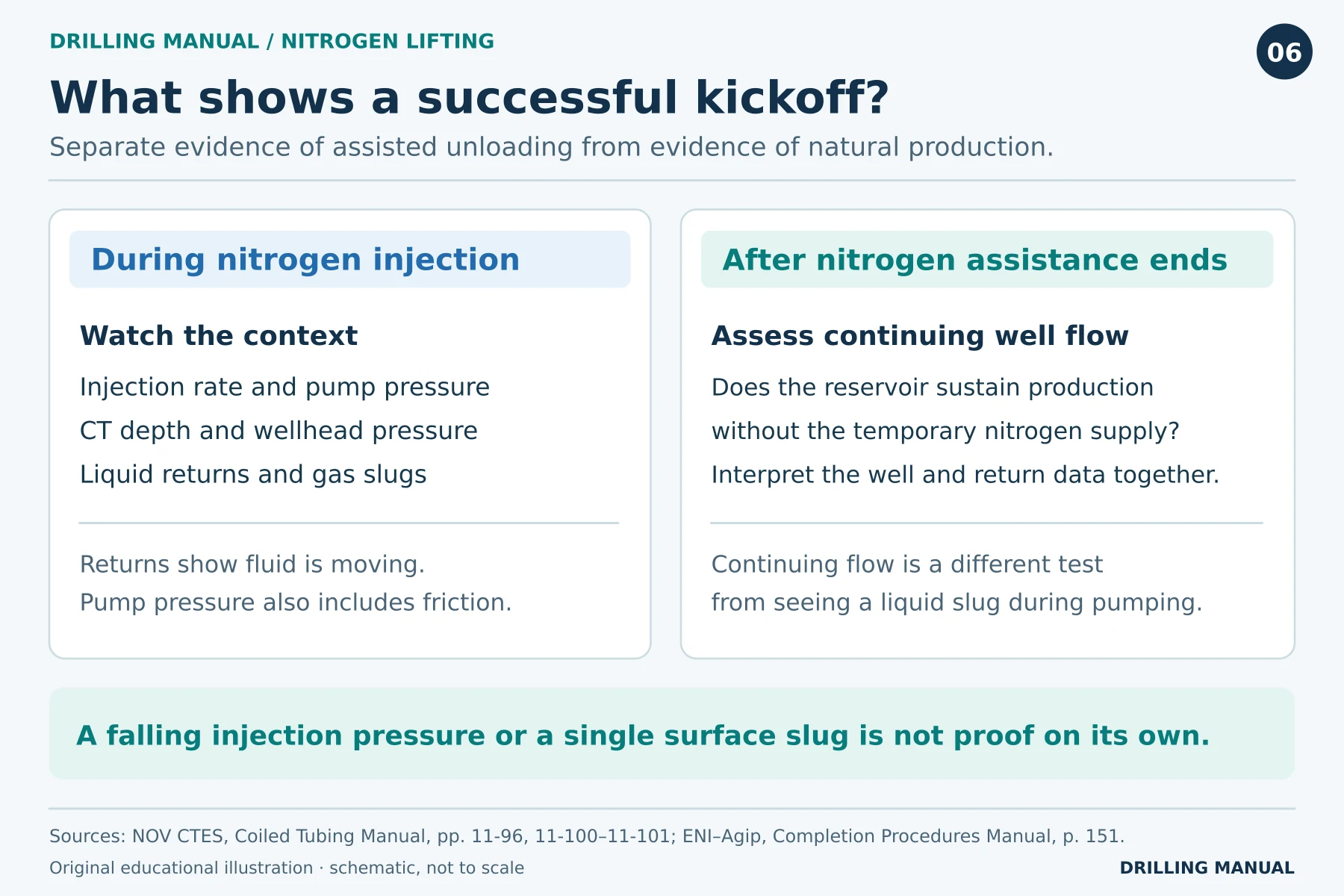
A useful handover separates three observations: what was injected, what returned during injection, and what the well did afterward. For example, “liquid recovered while nitrogen was pumping” is a defensible result even if later production data are unavailable. After the pump stops, a final gas slug may still contain injected nitrogen. Record how long production continued without further injection; a single post-injection return cannot establish a sustained restart. [1], [2]
Limitations and Practical Rules of Thumb
Nitrogen lifting changes the wellbore pressure profile; it does not increase reservoir pressure. Its value therefore depends on the source of the liquid load and the well’s ability to deliver fluid once that load falls. Other limitations include uneven drawdown, nitrogen dilution of gas samples and the cost of extended pumping. Viscous crude can also increase CT sticking risk. [1]
- Name the pressure point. For example, record whether a reported change concerns pump pressure, flowing wellhead pressure or bottomhole pressure.
- Separate vertical height from travel length. Use each for the part of the calculation it describes.
- Compare like conditions. Check for changes in depth and injection rate before interpreting a pressure trend.
- Define the result. Report liquid recovery, reservoir inflow and unassisted production separately when the evidence allows.
Surface arrangements also matter. For example, compressed gas stores energy, cryogenic liquid can cause cold injury, and released nitrogen can displace oxygen. In addition, alternating gas and liquid slugs can impose changing forces on return lines. These hazards and the CT pressure-control equipment need to be addressed in the well-specific program. [1]
Nitrogen Lifting Questions
Is nitrogen lifting the same as permanent gas lift?
Both use gas to assist fluid production. In the CT kickoff described here, the temporary string delivers nitrogen at the chosen depth. By comparison, an installed gas-lift completion can use valves in tubing mandrels for ongoing injection. The two arrangements therefore use different hardware and injection paths. [1], [3]
Can nitrogen volume be calculated from tubing capacity alone?
No. Tubing capacity describes geometry. Gas slippage, pressure, injection depth, return-path friction and reservoir contribution also affect unloading. Consequently, the gas requirement comes from a well-specific assessment rather than a one-for-one replacement of liquid volume. [1]
Does nitrogen returning at surface prove the reservoir is producing gas?
No, because injected nitrogen can itself reach the separator and dilute formation gas. Record whether nitrogen was pumping when a gas sample was taken. By contrast, a nitrogen lift does not add a lifting liquid that could mix with oil or formation-water samples. [1], [2]
What if the well lifts liquid but stops flowing afterward?
Report the two outcomes separately. The assisted operation recovered liquid; unassisted flow was not sustained under the observed conditions. Because sustained production depends on pressure, fluid mixture and flow rate, the observation alone does not identify which condition limited the well. [1]
Book References
- NOV CTES, Coiled Tubing Manual. Chapter 10, hydraulic pressure terms, pp. 10-2–10-3 (PDF 265–266); chapter 11, “Unloading a Well with Nitrogen,” pp. 11-96–11-102 (PDF 393–399). See also “Cleanup and Flowback,” p. 11-36 (PDF 333). Section revision 27 June 2014.
- ENI–Agip, Completion Procedures Manual. Revision 0, 28 June 1999, sections 12 and 13.6.1, pp. 139, 150–151. Used for applications and monitoring concepts.
- Petroleum Well Construction. John Wiley & Sons, Halliburton educational version, chapter 13, pp. 627–629, on installed gas-lift valves, mandrels and unloading.