
What Is The Drilling Rig Prime Mover:
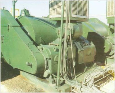
The Rig Prime Mover is considered the source of power for any drilling rig. On recent rigs, the prime mover contains one to four or more diesel engines. These diesel engines produce many thousand HP. Typically, diesel engines are connected directly to electric generators. The electrical power is then distributed by something called a controlled rectifier system around the drilling rig site. Drilling rigs that can alter the diesel power to electricity are called electric diesel rigs.
Older drilling rig designs transmit the power from the diesel engines to specific drilling rig components (drawworks, mud pumps, and rotary table) through mechanical belts, clutches & chains. A much smaller electrical generator on these drilling rigs provides power for lighting and any small electrical needs. These older rigs are referred to as mechanical or, more commonly, simply power rigs.
The Purpose of Testing & Inspecting Drilling Rig Prime Movers During Rig Acceptance / Commissioning
- Verify the proper working of all the instrumentation connected to the above equipment (pressure gauges, flow indicator, counters, etc.).
- Load tests all the SCRs (silicon-controlled rectifier system) driving the drilling mud pumps. Verify the maximum power delivered by the generator.
- Verify that all the diesel engine/generator groups work correctly.
- Verify the proper working of choke manifold power chokes and remote control panel.
- Pressure test the mud pumps and discharging lines, rig floor mud manifold, standpipe manifold, and top drive wash pipe.
Guidelines For Drilling Rig Prime Mover Inspection Tests
- Connect two mud pumps through the choke manifold and get them ready for circulation at a high flow rate and high pressure
- Connect the swivel head (or Top drive) with the choke manifold to circulate through the power choke at high pressure.
- Record the mud pump liners. It is preferable to have 6-inch liners or less installed to reach a pressure as high as possible, set the mud pump relief valve accordingly, and check the pulsation dampener pre-charge pressure.
- Connect on the main bus the minimum generators that can deliver enough power to drive the two mud pumps running at 3000-3500 lpm (or the maximum flow rate allowed for the acceptance test).
- Start pumping slowly with one mud pump with the power choke fully open and verify the following:
- Any leak along the mud pump discharge lines.
- Check if all parameters recorded are working correctly.
- Check if all pressure gauge stroke counters on different consoles show the same values.
- If there are no evident anomalies, increase the pump rate slowly up to the maximum rated speed allowed by the mud pump manufacturer.
- Close the power choke gradually to obtain one of the following conditions:
- The maximum power delivered from the diesel/generator.
- Maximum allowed pressure for the size of the liners installed on the mud pumps.
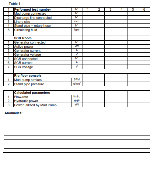
- Circulate enough at the above conditions to record reliable parameters as requested in Table n°1.
- Repeat the same test for all the other power groups using alternate equipment not used in the previous test (another mud pump, discharge line, standpipe, rotary hose, SCR, etc.).
Good Experience