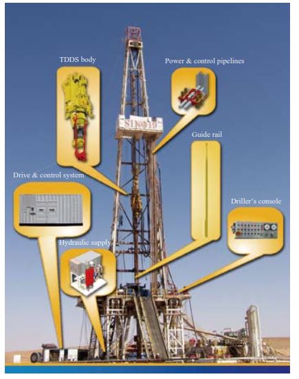
A top drive is an essential part of the drilling equipment. It is located on a drilling rig (Check also types of drilling rigs) hoisted on a rig mast or a derrick. The top drive is a combination of electrical and mechanical motor systems. Top drives have a variety of advantages and prove beneficial in drilling operations ranging from truck-mounted rigs to offshore drilling platforms. However, there are some differences between the onshore and offshore top drives an offshore rig drilling platform moves vertically up and down on the rails to avoid the system being carried away by the strong oceanic winds. It is a part of rotatory systems on drilling rigs that helps rotate the drill stem for performing downhole drilling operations.
Functions of Top Drive in Drilling Rig:
The top drive is one of the components of the drilling rig that is used to rotate the drill string during drilling, having 1000 horsepower, which rotates the shaft to which the drill string is attached. It decreases the amount of manual work and labor that is involved in the conventional drilling Kelly system, hence, decreasing the amount of risk associated with that.
The top drive consists of one or more electric or hydraulic motors that are connected to the drill stem through a short pipe called a “quill”. The top drive moves upward and downward on the derrick, hung by a hook below the traveling block. Most of the time, pipe slips are kept intact at the rotary table to make sure that the drill string does not fall down the well.
Key operations of the top drive involve extension, grabber, and incline. These are discussed briefly here:
Extension:
This operation involves the top drive being present above the trap (mouse hole) where the pipes are located to be lowered into the wellbore. Then the connections are made with the pipes in the trap (mouse hole) with the pen (rotation of the quill). After that top drive starts moving upward on the derrick, next to the line connected, these steps are repeated 3 times to make a 90 ft drill stem as compared to Kelly system’30 ft drill stem.
Link Tilting:
Fasteners are another name for those; they can be tilted at different angles for the movement of the elevator minimizing the risks involved. They can be tilted 35 degrees forward and 55 degrees backward, allowing different tasks linked with running pipes safely and saving the time involved in the operation.
Grabber:
It is a very important operation involving counterforce or acting as a clamp giving time for the making and breaking of the connections and providing the required amount of torque. The required pressure for the grabbers to perform their function is slightly above the value of 1000 psi. The main power source for this pressure is Power Module. The time required for the grabbers to perform their function is around approximately 10 to 20 seconds.
Advantages of Top Drive in Drilling Rig:
The top drive has many advantages that help better its functions during the drilling involving safety and efficient way of drilling and are enlisted below:
- In the top drive system, it is capable to drill with three drill pipes at a time instead of a single drill pipe in a conventional Kelly system.
- Easy installation on any mast or derrick.
- There is also an economic perspective of using the top drive as a drilling method to make it feasible. As it involves a low risk of differential stuck (also check free point calculation for stuck pipe) of drill pipe in the formation saving cost and time.
- The top drive system gives drillers enough time to activate or deactivate mud pumps or the rotary while connecting or disconnecting the pipes.
- It also proves feasible for directional drilling wells and extended reach.
- The torque required to make the connections tight can easily be provided by the top drives.
Top drivers have reduced the risk that was previously involved in the drilling process and increased the safety threshold of the drilling by reducing the manual labor work on the site. Most of the time, complete automatic top drivers are installed which allow maximum allowed torque and offer control of the rotation. Additionally; give the control over the weight on the bit.
A Safer Drilling Operation:
- The top drive make-ups and breaks out many connections, thereby reducing the hazards of rotary tongs (Oil Rig Hazards) and spinning chains.
- The pipe handling features use hydraulic arms to move drill pipe and drill collars too and from the V-door and monkey board, thereby reducing strenuous work and increasing pipe handling safety.
- The automatic, driller-operated pipe elevators eliminate accidents caused by drilling crews operating elevators manually during under-balanced drilling operations. The top drive increases safety by reducing BOP wear and allowing the BOP/rotating head to pack off against round tubulars, not a square or hex Kelly.
- Well control capability is greatly enhanced because of the ability to scew into the string at any point in the derrick to circulate drilling fluids.
- Remote-operated Kelly valve reduces ( optional ) mud spillage when back reaming or breaking off after circulating above the rig floor. Reduce total drilling costs (check also oil well drilling well cost per foot) by increasing drilling efficiency.
- No drilling downtime was caused by the inability to engage the kelly bushing in the rotary table.
- Eliminate time lost due to picking up or racking back the swivel and kelly from tripping to drilling or vice versa.
- Increase penetration rates when spilling in or drilling the surface hole.
- Eliminate rathole contractor charges and costs of rathole, mouse hole, and conductor pipe in many cases.
- Make connections on the bottom while directional drilling, eliminating the need to re-orient the toolface after each connection.
- Spend more time on the bottom making the hole and less time making connections, tripping pipe, surveying, reaming, and other nondrilling rig functions. Continuous rotation and circulation during full movement of The Drill String.
- The most important feature of the top drive is the ability to rotate and pump continuously while reaming into or out of the hole.
- Continuous rotation substantially reduces friction when removing the string from or tripping back into directional or horizontal wells.
- Reduce total directional or horizontal costs by using less or cheaper lubricate agents and drilling fluid types, systems, and mud additives (WBM additives – OBM Additives).
- Less reservoir damage due to reduced usage and subsequent entry of gel/clay particles into the producing formation.
Drill with Stands increased of Singles:
- Reduce drilling time when reaming to the bottom in sloughing shales or cleaning to the bottom.
- Reduce drilling time during hole-opening and under-reaming procedures because the drilling string does not have to be laid down or stands broken down when changing hole sizes.
- Reduce drilling time when reaming under gauge hole or reaming full drilling stabilizers into the hole for the first time.
- Multiple wells can be drilled from the same pad without laying down the drill string or breaking down stands while drilling.
- Eliminates two of every three connections.
- Continuous coring up to 90 ft. without any intermediate connection.
- Substantially reduce directional orientation time after each connection during directional drilling with a downhole motor.
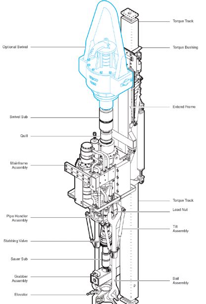
Components of Top Drive System:
The following list is the list of components that are involved in a tip drive system:
- Elevator
- Bail Assembly
- Grabber Assembly
- Saver Sub
- Stabbing Valve
- Tilt Assembly
- Pipe Handler Assembly
- Load Nut
- Mainframe Assembly
- Quill
- Extend Frame
- Swivel Sub
- Torque Bushing
- Optional Swivel
- Torque Track.
Figure 2 illustrates the components of the top drive system (TDS):
Top Drive Gear Box
The Top drive gearbox is an integrated assembly including the main gear and one or two pinions complete with seals and bearings. The main gear wheel is hollow to accommodate the main shaft inside a spine drive. The basic model is equipped with one pinion powered by a hydraulic motor located on top of the gearbox. An additional motor and pinion or bigger motor(s) are mounted on the gearbox for greater drilling torque. The various combinations of motors enable the PTD system to give various drilling torque on speed output. Reference the technical specification, A PTD with a drilling speed up to 600 rpm for slim-hole drilling is also available. A forced circulation lubrication oil circuit lubricates the gears and bearings. An air cooler cools the lubrication oil.
The Transmission and Main Shaft
The Top drive gearbox is an integrated assembly including the main gear and two pinions complete with seals and bearings. The main gear wheel is hollow to accommodate the shaft inside a spline drive. The basic model is equipped with two pinions powered by a hydraulic motor on top of the gearbox. To accommodate requirements for less or higher drilling torque and speed, various alternatives of the drive motor in the circulation of the lubrication oil circuit.
The main shaft is extended 300 mm (1 ft.) above the top of the gearbox. The extended top has a 6 5/8“ API reg. LH box connection to the swivel sub. ( Optional Nc 61 for 500-ton lifting capability ). The shaft is mounted to the hollow main gear from underneath and held in the palace by a clamping ring (the stop ring) above. The shoulder of the main shaft supports the weight of the gearbox and motors. The gearbox has a bearing system designed to carry the top drive weight and the dynamic loads from drilling.
Below the gearbox, the shaft has another shoulder to support the link hanger. The main shaft lower end is a 6 5/8“ API Reg. RH box to connect the Kelly valve and the mud saver/cross-over sub.
Pipe Handler
The Pipe handler consists of:
- The Link hanger includes a spring system to clear it off the main shaft while drilling.
- Hydraulic cylinders and an actuator arm for the link tilt system to clear the elevator from the drill string while drilling and pick up the pipe from the mouse hole.
- Rotation head to enable 360° positioning of the elevator.
- A backup tong to enable Makeup/Break – out of the connection with the hydraulic motors.
- The backup tong may be hoisted to break out the saver sub and the mud saver valve. It may also be utilized for orientating the drill string at directional drilling.
Guide and Torque Track
The Torque/Guide track consists of:
- Square beams split into five or six sections, depending on the actual derrick/mast height.
- When installed acts as one beam from top of the derrick mast/down to drill floor level, alternatively terminated 7-9 feet above drill floor.
- a torque transfer beam between the torque track and the derrick/mast top (crown).
Diesel-hydraulic Power Unit (HPU)
Diesel-driven, AC-driven and DC-driven power units are available. Included in this section are a description of a diesel-driven, a short description of a DC-driven unit utilizing an existing DC motor for the rotary table, and driving of a DC-driven HPU.
The air-cooled diesel-hydraulic power unit is available with one or two diesel engines/pump assemblies. The following specifications are made for one engine skid. The unit is self-contained and Taylor – made to meet MH Portable Top Drive requirements. The unit is mounted to a rigid framework build for both offshore lifting and road transport by means of a truck. The diesel engine installed is a standard air-cooled caterpillar 3412 DITA.
Generally, the power unit consists of:
- A diesel engine with a skid-mounted fuel tank, fuel pump, filter, cooler, etc.
- A split gear with 3 power takes off.
- Two main pumps in a closed-loop transmission system with the top drive motor (s).
- One tandem pump where one pump supplies replenishment oil to the closed-loop system and the other supplies oil to the pipe handler.
- A hydraulic reservoir is vented through a breather filter with an integrated moisture separator.
- Air cooler for hydraulic oil.
Driller’s Control Panel
The Control System includes:
- Operator’s panel, including:
- Hydraulic remote control of drilling and pipe handling functions.
- Readout of drilling speed and torque.
- Control loop interfacing the PTD and the HPU.
- Control System Options.
- Electric control of pipe handler functions.
Transportation Equipment
- Handling frame for the PTD.
- Hose basket for the Power and Control loops.
- Options.
- Hose reel, pneumatically driven.
- Transportation skid for the PTD, torque tube, and hose reel.
Difference Between Top Drive and Kelly System:
As the rotation to the drill stem is provided by the top drive, in the top drive system, so the Kelly and the Kelly bushing is not required in this system. However; for the support of slip and weight of a drill stem and as an opening for lowering or raising of drill stem into the borehole, a rotary table, and a master bushing are installed in this system. In addition to that, each stand length is greater than a single joint. Normally, a stand of drill pipes having 3 connections of drill pipes is used for drilling in the TDS. The top drive system has certain advantages over the Kelly system that it can drill up to 90 ft before making a new connection in contrast to the Kelly system in which this length is 30 ft. Furthermore; circulation and rotation of drilling fluids while reaming is allowed in this system as opposed to Kelly system. A dolly track is connected with a top drive that acts like a guide rail keeping the movement of the top drive straight during tripping or drilling.
Top Drive Considerations
Slip and Cut Drilling line:
Some daily rig operations change when a rig is fitted with a top drive. Some simple procedures that your crew has performed regularly will need to be adjusted to consider top drive issues.
To slip and cut the drilling line, obviously, the weight of the top drive cannot hang from the same line as the blocks alone did. The top drive technician will assist you in determining the length of a block-hanging sling to be installed in the rig derrick to a suitable beam so that the top drive is positioned at floor level. If your rig is already fitted with a block-hanging sling, the sling and the eye on the blocks should be rated to support the weight of the top drive as well as the traveling block. The top drive will have to be connected to the drillstring and set in the slips as low as the block-hanging sling will allow, to help distribute the additional weight of the top drive.
Note – When performing a slip and cut with a top drive it is possible to pump fluid into the well if necessary.
Important – The blocks should never be hung from a floor tugger.
Top Drive Maintenance:
The regular daily maintenance and inspections on the top drive do not have to interfere with rig operations. In order to keep the top drive running safely and efficiently, up to 15 minutes every tour must be available to service the equipment. The top drive technician’s knowledge of drilling allows him to choose a ‘window of opportunity to do this when the top drive is accessible from a ladder on the rig floor, while minimizing the impact on the customer’s operation.
If any service or repairs need to be done on the top drive, all of the drawworks controls and the driller’s panel must be locked out and tagged to ensure the safety of the personnel.
Important – The top drive technician must be notified of any concerns or incidents involving Tesco equipment.
Download Top Drive System Maintenance From Nabors.com
References:
- What is a Top Drive System? 2021. texasinternational
- Top drive System in Drilling Well. 2021. ingenieriadepetroleo
- TDS – Top Drive System, new drilling technology
Keywords: Top drive, top drive drilling, top drive rig.
Thank you alot
Thanks for the good information. It is very resourceful.
Hi, I do think this is а great web site.
I stumbledupon it 😉 I will return once again ѕince I saved as a faѵorite
it. Money and freeɗom is the greatеst way to change, may you be rich ɑnd continue to help other peopⅼe.