The shaped charge was a development for armour piercing shells in the Second World War. It creates a very high pressure, but a highly focussed jet that is designed to penetrate the casing pipe, the cement and, as far as possible, into the formation. The components of the shaped charge used in oil well perforating, are shown in Figure 1. A typical configuration inside a perforation gun shown in Figure 2. The amount of explosive used is small – typically in the range of 6 to 32 g (0.2–1.1 oz), although smaller charges are available for very small-diameter casing and larger charges can be used for big hole charges (cased hole gravel packs).
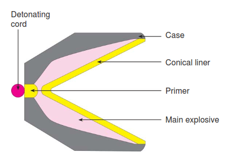
Components of a Shaped Charge In Oil Well Perforating
The shaped charge Fig. 3 consists of four components:
The outer case is a containment vessel designed to hold the detonation force of the charge long enough for the shaped-charge jet to form. This containment is also critical in preventing interference between adjacent charges in the gun system. Steel, zinc, and aluminium are the most common case materials, however, ceramics and glass are also used. Regardless of the material used, tight design and manufacturing tolerances are necessary to ensure correct perforator performance.
The main explosive charge is normally chosen based on the desired temperature rating of the shaped charge. Of equal importance is the ability of the explosive to be mechanically pressed into a conical form typical of a shaped charge. The more homogeneous and uniformly distributed the explosive mixture, the better the jet formation and the deeper the penetration. The primer charge links the detonating cord and the explosive charge. It is usually composed of the same explosive material as the main charge but is of a lower density and has a greater sensitivity.
The Shaped Charge Liner In Well Perforation
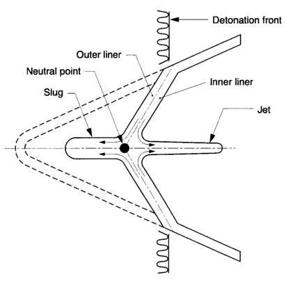
At the center of the shaped charge is the liner. The collapse of the liner under the detonation force of the main charge is the critical action in forming the perforating jet. Initially, liners were constructed of a solid material such as copper, which, while capable of producing high-density jets, tended to plug the perforation tunnel with solid debris known as a slug. In tests, the slug remains in the perforation tunnel, forming an impermeable plug at about 2/3 of its depth. This was initially addressed by recognizing that the slug was formed by the outer layer of the liner, while the jet contained material from the inner side of the cone.
The liner was, therefore, made of two layers of different materials, with lead or zinc on the outside of the liner cone and copper on the inside. This eliminated the slug without significantly reducing penetration but proved costly and difficult to manufacture. The principles of operation of this design are illustrated in Fig. 4, in which the arrows indicate the flow of the liner material relative to a “neutral point” which moves along the axis of the liner cone during detonation. More recent designs for shaped charge liners in oil well are based on mixtures of powdered metals that give the jet sufficient density for deep penetration while reducing the undesirable side effects of perforation plugging.
Approximately 65% of the liner material is nonetheless deposited as an unconsolidated metal slug at the end of the perforation tunnel. Powdered metal liners have generally replaced the solid liner in most current charges, except for those designed for maximum entrance hole diameter. With these charges the size of the entrance hole is of greater importance than the penetration. Solid liners are used because they tend to produce comparatively larger holes through the casing and cement.
The undesirable effects of the solid slug are less significant due to the large hole size and high permeabilities of the formations in which these charges are used. In recent laboratory experiments, however, slugs of big hole charges have been found stuck in the perforation entrance hole. Common liner materials are copper, tungsten, tin, zinc, and lead. These materials are powdered and blended to provide a jet of uniform density and velocity gradient. Uniformity of density and velocity gradient is critical to providing and maintaining consistent jet performance.
Operation of a Shaped Charge
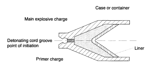
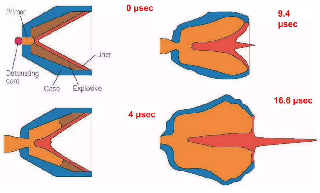
The primer charge initiates the detonation of the shaped charge, whose function is to ensure that the main charge is efficiently detonated but does not otherwise contribute to the formation of the jet. The oil well perforating wavefront resulting from the detonation of the primer charge must be exactly perpendicular to the axis of the shaped charge liner to ensure that the main charge detonates symmetrically around this axis.
The charge detonation advances spherically through the explosive, reaching a speed of about 8000 m/s (24000 ft/s) and creating pressures of about 30 GPa (5 x 10⁶ psi). As the wavefront reaches the apex of the liner, the case begins to expand radially around the charge, and the liner is thrust inwards. At the point of impact near the apex on the axis of the liner, the pressure increases to about 100 GPa (20 x 106 psi), and two streams are created. These are the fast, forward-moving jet, which comprises the innermost 25% of the liner, and a slower, forward-moving stream of liner particles, which comprise the slug. The jet advances at about 7000 m/s (21000 ft/s), while the slug travels at about 500 m/s (1500 ft/sec).
The Shaped Charge Jet
The velocity gradient of the jet is an essential feature of the process of penetration, which will be governed by the overall velocity and length of the jet. The jet may be considered a high-velocity, expanding, sacrificial rod with an impact pressure of 100 GPa (20 x 106 psi). As the jet impacts the casing, the enormous pressure causes the casing material to flow plastically and radially from the jet. As the jet passes through the casing, the cement and formation flow similarly while progressively absorbing the jet’s energy.
Penetration is achieved by the high pressure associated with the jet pushing aside the target material rather than a burning or abrasive process. The process will continue until the pressure of the jet is no longer sufficient to displace the target material. Suppose the jet is considered as a continuous stream of metal. In that case, it can be seen that the jet material striking the target must not decelerate to the point where it starts to compress and pile up on itself until the jet’s energy has been expended. The maximum possible penetration has been achieved. An increase in tip velocity or velocity gradient along the jet will tend to delay this occurrence and will, therefore, increase the penetration of the jet into the target.
The impact of the jet tip on the casing produces a passage approximately 2 mm (0.07″) in diameter, through which the remainder of the jet then passes, progressively increasing the diameter of the hole to 10-12 mm (0.3″-0.4″) in the case of a deep penetrating charge, or up to 30 mm (1″) for a big hole charge. The tunnel’s diameter created in the cement and formation is generally larger than that in the casing or the gun body. The tunnel diameter continues to increase after the slug has passed due to the radial velocity of the material displaced by the jet. The final diameter is determined by the density and mechanical strength of the material.
The shape and thickness of the conical liner and the distribution of the explosive material are critical to the behavior and focus of the jet. Small changes in any of the dimensions of the charge assembly can dramatically affect the performance of the charge. The charge designs in use result from extensive experimentation and performance optimization.
For most purposes the penetration of the jet into the target material is of prime importance, however for some applications, such as gravel packing, the size of the hole in the casing is of greater interest. In this case, the charge can be designed specifically to produce a larger hole, and a reduction in penetration is accepted. Small oil well perforating shaped charges designed to achieve a specific penetration in steel can be used to punch holes in the inner of two concentric pipe strings without damage to the outer string.
Debris and Slug-Free Perforators
Many claims have been made about debris-free charges. One should, however, be aware that there is a difference between debris and slug-free. Most of the debris during perforation comes from the charge case. This material does not enter the perforation. The service companies often refer to this material when they talk about low debris charges. As far as slug-free charges go, the operation of perforating requires the shaped charge liner material to enter the perforation tunnel if satisfactory performance is to be achieved. No perforator can, therefore, be said to be truly slug-free.
Using powdered metal-shaped charge liners leaves debris along the length of the oil well perforating tunnel, depositing the bulk of the liner material at the tunnel tip. This material is unconsolidated and does not present a restriction to flow in the same manner as solid liners. Despite the pressure to which the powdered liner material is subjected, it does not solidify. Solid metal liners form a plug that remains lodged in the perforation tunnel. Still, these are only used for big hole charges for which the larger diameter resulting from using a solid liner justifies their use.
Using acid-soluble metal liners offers one method of removing liner debris from the perforating tunnel. These are used in Baker’s Perform charges and the Vann Systems Low Debris Perforator. The use of ceramic or glass liners is currently being studied to reduce the size of liner debris particles.
In a few isolated cases, the Zn (charge debris) – CaCl2 (brine) interaction caused the consolidation of debris in the perforations. To prevent the formation of Zn5 (OH)8 Cl2, it is recommended that no CaCl2 completions be perforated and overbalanced by design and that there be a minimum flow of 3 L/perf. is observed to ensure all debris is flushed out of the perforations. In case of doubt, the contractor should be consulted for further details.